Page 1431 of 6000

6E–314
ENGINE DRIVEABILITY AND EMISSIONS
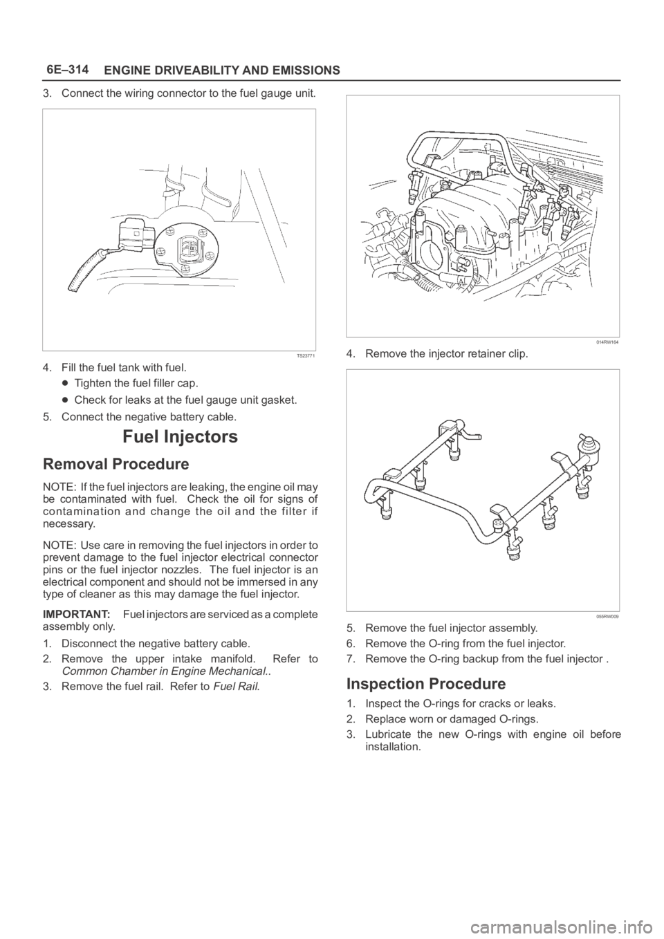
3. Connect the wiring connector to the fuel gauge unit.
TS23771
4. Fill the fuel tank with fuel.
Tighten the fuel filler cap.
Check for leaks at the fuel gauge unit gasket.
5. Connect the negative battery cable.
Fuel Injectors
Removal Procedure
NOTE: If the fuel injectors are leaking, the engine oil may
be contaminated with fuel. Check the oil for signs of
contamination and change the oil and the filter if
necessary.
NOTE: Use care in removing the fuel injectors in order to
prevent damage to the fuel injector electrical connector
pins or the fuel injector nozzles. The fuel injector is an
electrical component and should not be immersed in any
type of cleaner as this may damage the fuel injector.
IMPORTANT:Fuel injectors are serviced as a complete
assembly only.
1. Disconnect the negative battery cable.
2. Remove the upper intake manifold. Refer to
Common Chamber in Engine Mechanical..
3. Remove the fuel rail. Refer to
Fuel Rail.
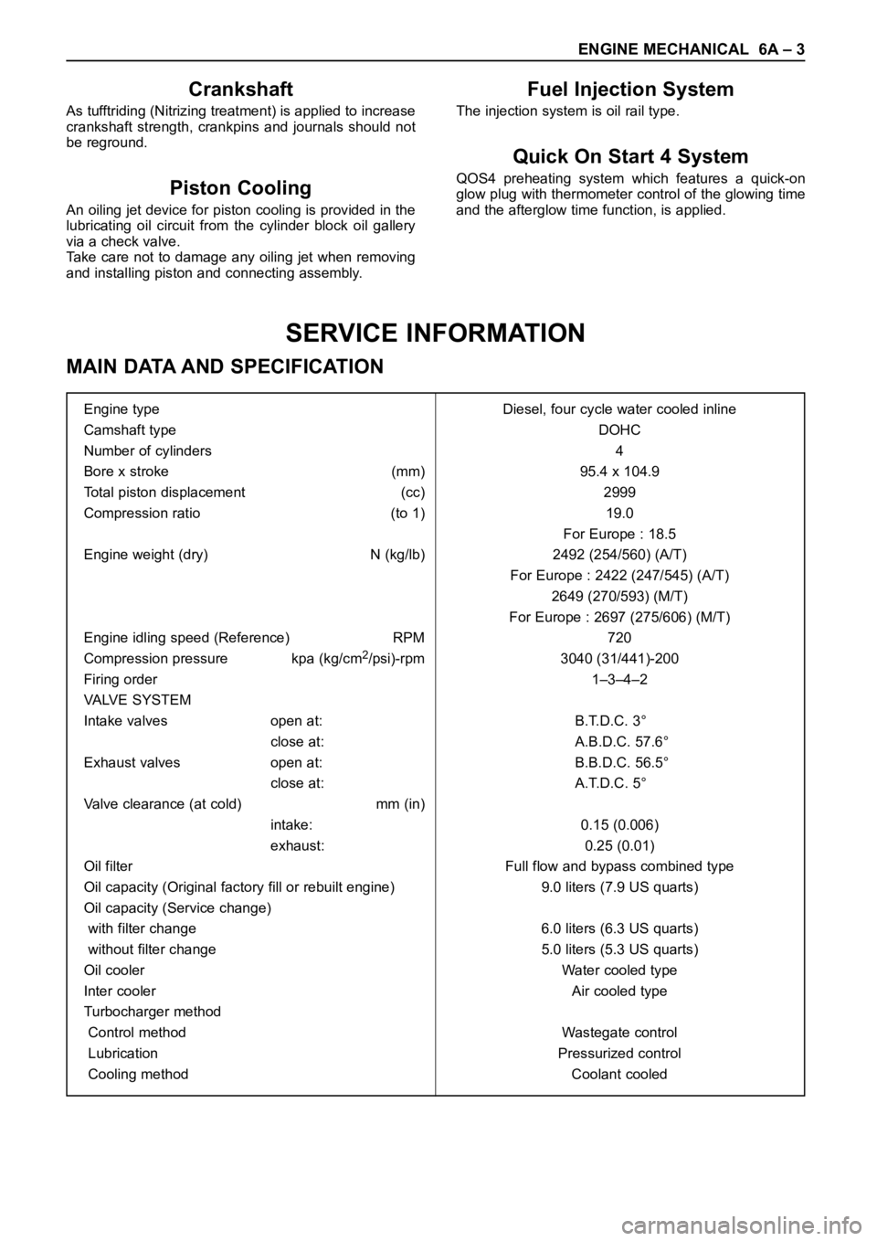
014RW164
4. Remove the injector retainer clip.
055RW009
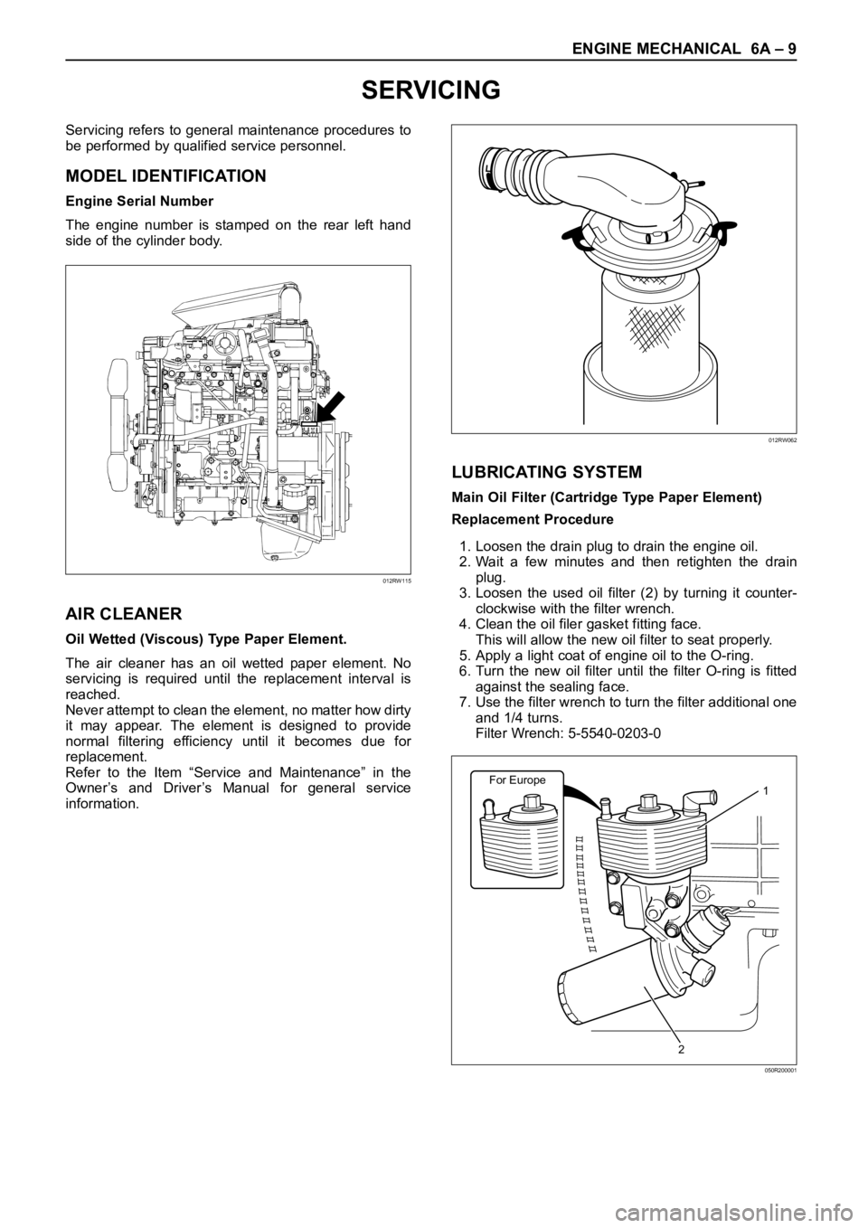
5. Remove the fuel injector assembly.
6. Remove the O-ring from the fuel injector.
7. Remove the O-ring backup from the fuel injector .
Inspection Procedure
1. Inspect the O-rings for cracks or leaks.
2. Replace worn or damaged O-rings.
3. Lubricate the new O-rings with engine oil before
installation.
Page 1736 of 6000

ENGINE MECHANICAL 6A – 3
SERVICE INFORMATION
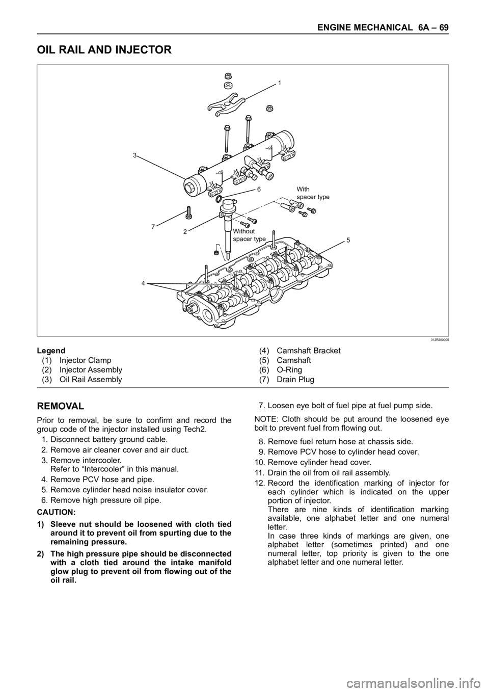
MAIN DATA AND SPECIFICATION
Engine type Diesel, four cycle water cooled inline
Camshaft type DOHC
Number of cylinders 4
Bore x stroke (mm) 95.4 x 104.9
Total piston displacement (cc) 2999
Compression ratio (to 1) 19.0
For Europe : 18.5
Engine weight (dry) N (kg/lb) 2492 (254/560) (A/T)
For Europe : 2422 (247/545) (A/T)
2649 (270/593) (M/T)
For Europe : 2697 (275/606) (M/T)
Engine idling speed (Reference) RPM 720
Compression pressure kpa (kg/cm
2/psi)-rpm 3040 (31/441)-200
Firing order 1–3–4–2
VALVE SYSTEM
Intake valves open at: B.T.D.C. 3°
close at: A.B.D.C. 57.6°
Exhaust valves open at: B.B.D.C. 56.5°
close at: A.T.D.C. 5°
Valve clearance (at cold) mm (in)
intake: 0.15 (0.006)
exhaust: 0.25 (0.01)
Oil filter Full flow and bypass combined type
Oil capacity (Original factory fill or rebuilt engine) 9.0 liters (7.9 US quarts)
Oil capacity (Service change)
with filter change 6.0 liters (6.3 US quarts)
without filter change 5.0 liters (5.3 US quarts)
Oil cooler Water cooled type
Inter cooler Air cooled type
Turbocharger method
Control method Wastegate control
Lubrication Pressurized control
Cooling method Coolant cooled
Crankshaft
As tufftriding (Nitrizing treatment) is applied to increase
crankshaft strength, crankpins and journals should not
be reground.
Piston Cooling
An oiling jet device for piston cooling is provided in the
lubricating oil circuit from the cylinder block oil gallery
via a check valve.
Take care not to damage any oiling jet when removing
and installing piston and connecting assembly.
Fuel Injection System
The injection system is oil rail type.
Quick On Start 4 System
QOS4 preheating system which features a quick-on
glow plug with thermometer control of the glowing time
and the afterglow time function, is applied.
Page 1742 of 6000

ENGINE MECHANICAL 6A – 9
SERVICING
Servicing refers to general maintenance procedures to
be performed by qualified service personnel.
MODEL IDENTIFICATION
Engine Serial Number
The engine number is stamped on the rear left hand
side of the cylinder body.
AIR CLEANER
Oil Wetted (Viscous) Type Paper Element.
The air cleaner has an oil wetted paper element. No
servicing is required until the replacement interval is
reached.
Never attempt to clean the element, no matter how dirty
it may appear. The element is designed to provide
normal filtering efficiency until it becomes due for
replacement.
Refer to the Item “Service and Maintenance” in the
Owner’s and Driver’s Manual for general service
information.
LUBRICATING SYSTEM
Main Oil Filter (Cartridge Type Paper Element)
Replacement Procedure
1. Loosen the drain plug to drain the engine oil.
2. Wait a few minutes and then retighten the drain
plug.
3. Loosen the used oil filter (2) by turning it counter-
clockwise with the filter wrench.
4. Clean the oil filer gasket fitting face.
This will allow the new oil filter to seat properly.
5. Apply a light coat of engine oil to the O-ring.
6. Turn the new oil filter until the filter O-ring is fitted
against the sealing face.
7. Use the filter wrench to turn the filter additional one
and 1/4 turns.
Filter Wrench: 5-5540-0203-0
012RW115
012RW062
For Europe1
2
050R200001
Page 1752 of 6000
ENGINE MECHANICAL 6A – 19
Injector
Nꞏm (kgꞏm/lbꞏft)
E06R200022
With
spacer type
Without
spacer type
20Nꞏm(2.0kgꞏm/14 Ib ft)
7Nꞏm(0.7kgꞏm/61 Ib in)
Recheck tightening torque
after tighten the oil rail
Apply engine oil on the
thread of stud bolts
20Nꞏm(2.0kgꞏm/14 Ib ft)
Tighten 30Nꞏm(3.1kgꞏm/22 Ib ft)
Then loosen it again tighten with
24Nꞏm(2.4kgꞏm/17 Ib ft)
Apply engine oil
both side
Page 1776 of 6000
ENGINE MECHANICAL 6A – 43
CYLINDER HEAD GASKET
12
13
14
15
8
3
4
5 6
10
11 9
With
spacer type
Without
spacer type
1 7
2
011R200002
Legend
(1) Cylinder Head Noise Insulator Cover
(2) Insulator
(3) Bolt and Gasket
(4) Oil Seal
(5) Gasket
(6) Cylinder Head Cover
(7) Bolt, Stud and Rubber Mounting
(8) Injector Clamp(9) Oil Rail
(10) Injector Assembly
(11) Camshaft Carrier
(12) Cylinder Head Bolt
(13) Cylinder Head Assembly
(14) Cylinder Head Gasket
(15) Cylinder Block
Page 1780 of 6000
ENGINE MECHANICAL 6A – 47
CAMSHAFT
2 1
6With
spacer type
Without
spacer type
13 14
8
12
11
109
3
4
7
5
012R200004
Legend
(1) Nut and Washer
(2) Injector Clamp
(3) Nut
(4) Bolt
(5) Oil Rail Assembly
(6) Spacer (If equipped) and Bolt
(7) Injector Assembly(8) Camshaft
(9) Camshaft Carrier
(10) Plug
(11) Oil Seal
(12) Camshaft Bracket
(13) Gasket
(14) Gasket
Page 1802 of 6000

ENGINE MECHANICAL 6A – 69
OIL RAIL AND INJECTOR
REMOVAL
Prior to removal, be sure to confirm and record the
group code of the injector installed using Tech2.
1. Disconnect battery ground cable.
2. Remove air cleaner cover and air duct.
3. Remove intercooler.
Refer to “Intercooler” in this manual.
4. Remove PCV hose and pipe.
5. Remove cylinder head noise insulator cover.
6. Remove high pressure oil pipe.
CAUTION:
1) Sleeve nut should be loosened with cloth tied
around it to prevent oil from spurting due to the
remaining pressure.
2) The high pressure pipe should be disconnected
with a cloth tied around the intake manifold
glow plug to prevent oil from flowing out of the
oil rail.7. Loosen eye bolt of fuel pipe at fuel pump side.
NOTE: Cloth should be put around the loosened eye
bolt to prevent fuel from flowing out.
8. Remove fuel return hose at chassis side.
9. Remove PCV hose to cylinder head cover.
10. Remove cylinder head cover.
11. Drain the oil from oil rail assembly.
12. Record the identification marking of injector for
each cylinder which is indicated on the upper
portion of injector.
There are nine kinds of identification marking
available, one alphabet letter and one numeral
letter.
In case three kinds of markings are given, one
alphabet letter (sometimes printed) and one
numeral letter, top priority is given to the one
alphabet letter and one numeral letter.
1
6
27
3
5
4
With
spacer type
Without
spacer type
012R200005
Legend
(1) Injector Clamp
(2) Injector Assembly
(3) Oil Rail Assembly(4) Camshaft Bracket
(5) Camshaft
(6) O-Ring
(7) Drain Plug
Page 1835 of 6000
6B – 2 ENGINE COOLING
Legend
(1) Turbocharger
(2) Thermostat
(3) Reservoir Tank
(4) Radiator
(5) Bypass(6) Oil Cooler
(7) Cooling fan
(8) Water Pump
(9) Thermo Valve
(10) Car Heater
(11) EGR Cooler
GENERAL DESCRIPTION
COOLANT FLOW
1
6
9
9
For Europe only
10
8
4
325
7
11
032R200001
The cooling system is a pressurized coolant forced
circulation type which consists of water pump,
thermostat, cooling fan, radiator and other components. The circulating coolant cools the lubricating oil in the oil
cooler and turbocharger.