1998 OPEL FRONTERA check oil
[x] Cancel search: check oilPage 692 of 6000

4C–26
DRIVE SHAFT SYSTEM
Reassembly
1. Install DOJ case to bracket.
2. Install oil seal and fix snap ring.
3. Install bearing and fix snap ring.
4. Install bracket to axle case. Tighten the bracket bolt to
the specified torque.
Torque: 116 Nꞏm (11.8 kgꞏm/85 lb ft)
5. Apply 150g of the specified grease in BJ .
6. Install dust seal .
7. Apply a thin coat of grease to the shaft for smooth
installation then install bellows.
8. Install band. Note the setting direction. After
installation, check that the bellows is free from
distortion.
412RS017
9. Install another bellows and fix band.
10. Install the ball guide with the smaller diameter side
ahead onto the shaft.
11. Install ball retainer.
12. Using snap ring pliers, install the snap ring (1)
securing the ball retainer to the shaft.
412RS013
13. Align the track on the ball (1) retainer with the window
in the cage, and install the six balls into position.
412RS018
14. Install spacer.
15. Install snap ring.
16. Enclose 150g of the specified grease in DOJ case,
then install drive shaft joint assembly. After
reassembly, move the DOJ longitudinally several
times to get to fit.
17. Install the circlip (1) so that open ends are positioned
away from the ball groove.
Page 697 of 6000

4C–31 DRIVE SHAFT SYSTEM
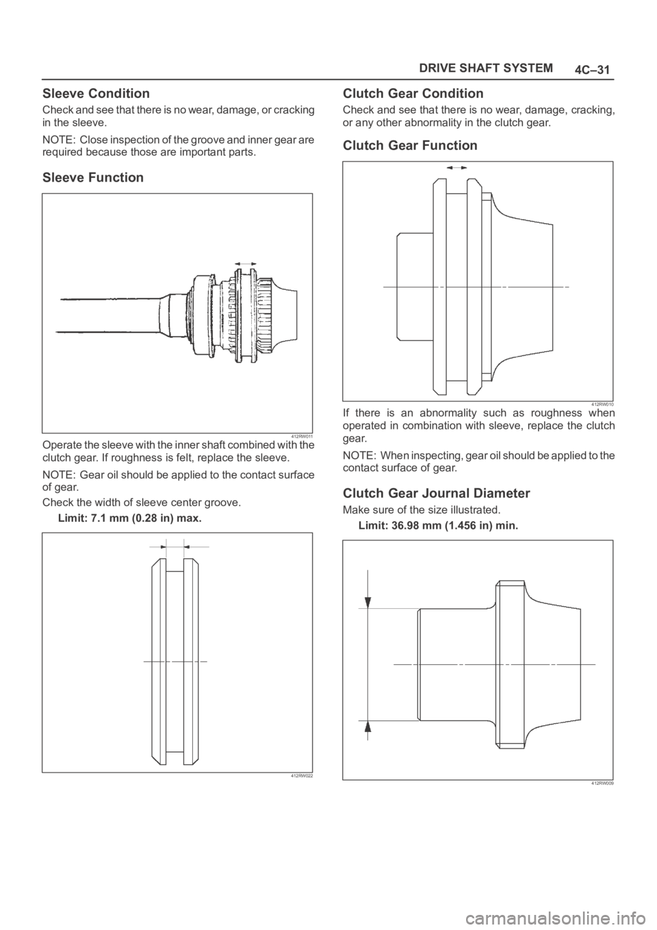
Sleeve Condition
Check and see that there is no wear, damage, or cracking
in the sleeve.
NOTE: Close inspection of the groove and inner gear are
required because those are important parts.
Sleeve Function
412RW011Operate the sleeve with the inner shaft combined with the
clutch gear. If roughness is felt, replace the sleeve.
NOTE: Gear oil should be applied to the contact surface
of gear.
Check the width of sleeve center groove.
Limit: 7.1 mm (0.28 in) max.
412RW022
Clutch Gear Condition
Check and see that there is no wear, damage, cracking,
or any other abnormality in the clutch gear.
Clutch Gear Function
412RW010If there is an abnormality such as roughness when
operated in combination with sleeve, replace the clutch
gear.
NOTE: When inspecting, gear oil should be applied to the
contact surface of gear.
Clutch Gear Journal Diameter
Make sure of the size illustrated.
Limit: 36.98 mm (1.456 in) min.
412RW009
Page 754 of 6000

TRANSFER CASE (STANDARD TYPE)
4D1–33
NOTE: Do not reuse the stopper plate. (Shift On The Fly
model)
24. Disassemble the 2WD–4WD clutch hub and sleeve
assembly.
Springs (1) (Shift On The Fly model)
Inserts (2) (Shift On The Fly model)
Clutch Hub (3)
Sleeve (4)
226RW133
25. Use a bench press and the ball bearing remover
5–8840–0015–0 (J–22912–01) to remove the ball
bearing (4) from front output shaft (5).
262RW071
26. Remove bearing snap ring (29) from transfer case.
27. Remove the counter gear assembly (28) from the
transfer case (1).
28. Use a pair of snap ring pliers to remove the snap ring
(20).29. Use a bench press and the bearing remover
5–8840–0015–0 (J–22912–01) to remove the ball
bearing (21).
30. Use a pair of snap ring pliers to remove the snap ring
(27).
31. Use a bench press and the bearing remover
5–8840–0015–0 (J–22912–01) to remove the ball
bearing (26).
226RW191
32. Remove the spacer (25).
33. Remove the belleville spring (24).
34. Remove the sub–gear (anti–lash plate) (23) from the
counter gear (22).
Inspection and Repair
1. Make the necessary repair or parts replacement if
wear, damage or any other abnormal conditions are
found during inspection.
2. Wash all parts thoroughly in clean solvent. Be sure all
old lubricant, metallic particles, dirt, or foreign
material are removed from the surfaces of every part.
Apply compressed air to each oil feed port and
channel in each case half to remove any obstructions
or cleaning solvent residue.
Gears
1. Inspect all the gear teeth for signs of excessive wear
or damage and check all the gear splines for burrs,
nicks, wear or damage. Remove the minor nicks or
scratches on an oil stone. Replace any part exhibiting
excessive wear or damage.
Front Output Gear Inside Diameter
1. Use an inside dial indicator to measure the gear inside
diameter.
Page 755 of 6000

4D1–34
TRANSFER CASE (STANDARD TYPE)
2. If the measured value exceeds the specified limit, the
gear must be replaced.
Gear inside diameter
Standard : 48.000–48.013 mm (1.8898–1.8903 in)
Limit : 48.10 mm (1.894 in)
226RS040
Clutch Hub Spline Play
1. Set a dial indicator to the clutch hub to measured.
2. Move the clutch hub as far as possible to both the right
and the left.
Note the dial indicator reading.
3. If the measured value exceeds the specified limit, the
clutch hub must be replaced.
Clutch hub spline play
Standard : 0–0.1 mm (0–0.004 in)
Limit : 0.2 mm (0.008 in)
226RS042
Bearings
1. Inspect the condition of all the needles and ball
bearings. Wash bearings thoroughly in a cleaning
solvent. Apply compressed air to the bearings.
NOTE: Do not allow the bearings to spin. Turn them
slowly by hand. Spinning bearings may damage the
rollers.
2. Lubricate the bearings with a light oil and check them
for roughness by slowly turning the race by hand.
Ball Bearing Play
1. Use a dial indicator to measure the ball bearing play.
2. If the measured value exceeds the specified limit, the
ball bearing must be replaced.
Limit : 0.2 mm (0.008 in)
226RS043
Synchronizers
The synchronizer hubs and sliding sleeves are a selected
assembly and should be kept together as originally
assembled.
Clean synchronizer components with clean solvent and
air dry.
Inspect the components for the following:
Teeth for wear, scuffs, nicks, burrs or breaks.
Keys and springs for wear, cracks or distortion,
replace if these conditions are present.
If scuffed, nicked or burred conditions cannot be
corrected with a soft stone or crocus cloth, replace the
component.
Block Ring and Insert Clearance
1. Use a vernier caliper to measure the clearance
between the block ring and the insert.
2. If the measured value exceeds the specified limit, the
block ring and the insert must be replaced.
Block ring and insert clearance
Standard : 2.46–2.74 mm (0.097–0.108 in)
Page 773 of 6000

4D2–6
TRANSFER CASE (TOD)
2. Using the oil seal installer 5-8840-2412-0 (J-42804),
install the oil seal.
NOTE: When installing the oil seal, pay attention to the
direction.
261RW051
Rear Output Shaft Oil Seal
Distance between the transfer case end and oil seal.
NOTE: When installing the oil seal to the specified
dimension, be careful not to damage it.
Distance : 9.85 — 10.35mm (0.39 — 0.41 in)
A04RW004
3. Mount the rear companion flange, O-ring , washer,
and nut to the transfer case in this order.
4. Using the flange holder 5-8840-0133-0 (J-8614-11),
install a new end nut.
Torque : 167 Nꞏm (17 kgꞏm /123 lb ft)
5. Using the punch 5-8840-2293-0 (J-39209), stake the
end nut at two spots.
NOTE: Check the staked end nut is free from cracks.
266RW028
260RW007
6. Install the rear propeller shaft to the transfer case and
tighten to the specified torque.
Torque : 63 Nꞏm (6.4 kgꞏm /46 lb ft)
Page 775 of 6000

4D2–8
TRANSFER CASE (TOD)
Unit Repair
Inspection
Before disassembling and after assembling, check the
following items on the transfer connector terminals.
No.
NAMECONTENTS
1Ref . (Ref . )Rear speed sensor refer-
ence output
2Ref . (Frt . )Front speed sensor refer-
ence output
3SW GNDSW GND
44H SW (+)4H SW plus terminal
5Rer . (+)Rear speed sensor plus
6Frt . (+)Front speed sensor plus
7POWER GNDPower GND
8SOL (+)Electromagnetic solenoid
9COM (–) (Ref .)Rear speed sensor GND
10COM (–) (Frt .)Front speed sensor GND
11NC
124L SW (+)4L SW plus terminal
810RW002
4H and 4L switches
Check whether the 4H switch (terminals 4 and 7) and 4L
switch (terminals 12 and 3 ) work as specified in the table
below. If yes, the continuity is established on these
switches. If not, check the switches, shift rails, transfer
case, and rear cover, and replace the failed parts.
SHIFT POSI-
TION
PIN 4 (4 to 7)PIN 12 (3 to 12)
HIGHOFFOFF
(NEUTRAL)ONON
4LOFFON
Power GND
Check that there is a continuity between the power GND
pin (terminal 7) and transfer case. If not, replace the
grounding wire.
Resistance of electromagnetic coil
Check the resistance between electromagnetic clutch
solenoid (terminal 8) and power GND (terminal 7). If not,
replace the electromagnetic coil.
Standard : 1.4
2.0
Allowable : 1.0 5.0
Page 793 of 6000

4D2–26
TRANSFER CASE (TOD)
265RW007
Inspection and Repair
When wear, damage, or any other defects are observed
during the inspection, the part or parts must be repaired or
replaced. Wash all the parts with clean solvent, and
check that old oil, metallic particles, dirt, or foreign
materials are completely removed. Blow the air into oil
holes and grooves to remove foreign materials or residual
detergent.
Chain
Check whether the face that contacts the sprocket is
free from excessive wear or damage. If defects are
observed, replace the part.
If the chain interference mark is found on the inside
w a l l o f t h e t r a n s f e r c o v e r o r t h e c h a i n i s s o s l a c k t h a t a
skipped engagement occurs between the chain and
sprocket, replace the chain.
Sprocket
Check whether the sprocket tooth surface is
excessively worn or damaged, and there is evidence
of burrs, chipping, wear, or damage on the gear
spline. Remove minor flaws or scratches with oil
stone. If excessive wear or damage is observed,
replace the part.
If excessive wear or damage is observed on the
sprocket inside sliding surface, replace the part.
Gear
Check whether the gear tooth surface is excessively
worn or damaged, and there is evidence of burrs,
chipping, wear, or damage on the gear spline.
Remove minor flaws or scratches with oil stone. If
excessive wear or damage is observed, replace the
part.
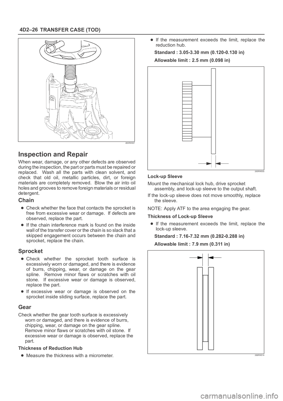
Thickness of Reduction Hub
Measure the thickness with a micrometer.
If the measurement exceeds the limit, replace the
reduction hub.
Standard : 3.05-3.30 mm (0.120-0.130 in)
Allowable limit : 2.5 mm (0.098 in)
265RW005
Lock-up Sleeve
Mount the mechanical lock hub, drive sprocket
assembly, and lock-up sleeve to the output shaft.
If the lock-up sleeve does not move smoothly, replace
the sleeve.
NOTE: Apply ATF to the area engaging the gear.
Thickness of Lock-up Sleeve
If the measurement exceeds the limit, replace the
lock-up sleeve.
Standard : 7.16-7.32 mm (0.282-0.288 in)
Allowable limit : 7.9 mm (0.311 in)
266RW014
Page 795 of 6000

4D2–28
TRANSFER CASE (TOD)
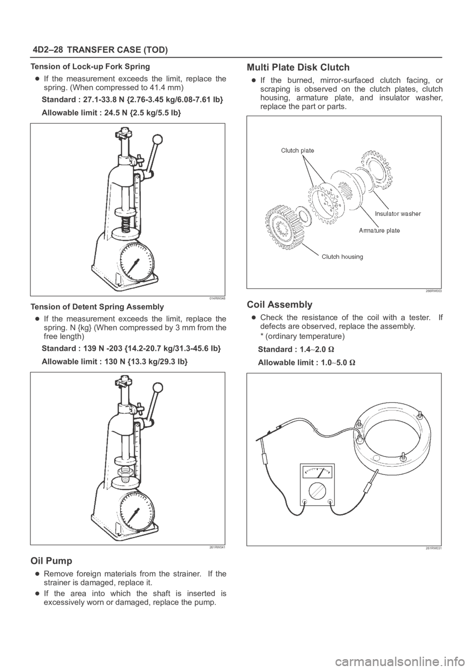
Tension of Lock-up Fork Spring
If the measurement exceeds the limit, replace the
spring. (When compressed to 41.4 mm)
Standard : 27.1-33.8 N {2.76-3.45 kg/6.08-7.61 Ib}
Allowable limit : 24.5 N {2.5 kg/5.5 Ib}
014RW048
Tension of Detent Spring Assembly
If the measurement exceeds the limit, replace the
spring. N {kg} (When compressed by 3 mm from the
free length)
Standard : 139 N -203 {14.2-20.7 kg/31.3-45.6 Ib}
Allowable limit : 130 N {13.3 kg/29.3 Ib}
261RW041
Oil Pump
Remove foreign materials from the strainer. If the
strainer is damaged, replace it.
If the area into which the shaft is inserted is
excessively worn or damaged, replace the pump.
Multi Plate Disk Clutch
If the burned, mirror-surfaced clutch facing, or
scraping is observed on the clutch plates, clutch
housing, armature plate, and insulator washer,
replace the part or parts.
266RW003
Coil Assembly
Check the resistance of the coil with a tester. If
defects are observed, replace the assembly.
* (ordinary temperature)
Standard : 1.4
2.0
Allowable limit : 1.05.0
261RW031