Page 5973 of 6000

7A–192 AUTOMATIC TRANSMISSION (AW30-40LE)
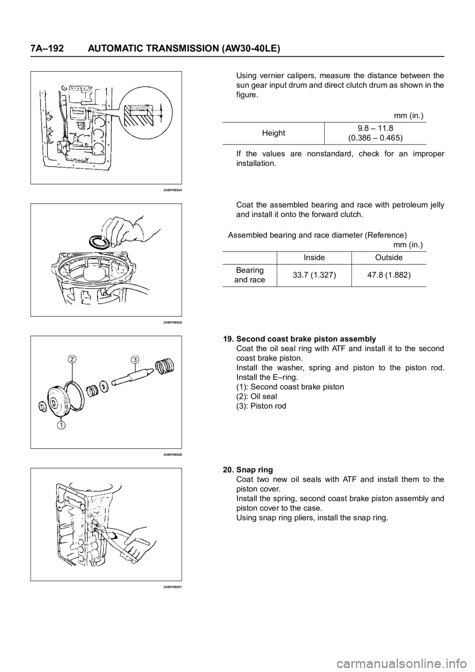
248RY00024
248RY00025
248RY00026
248RY00027
Using vernier calipers, measure the distance between the
sun gear input drum and direct clutch drum as shown in the
figure.
If the values are nonstandard, check for an improper
installation.
Coat the assembled bearing and race with petroleum jelly
and install it onto the forward clutch.
19. Second coast brake piston assembly
Coat the oil seal ring with ATF and install it to the second
coast brake piston.
Install the washer, spring and piston to the piston rod.
Install the E–ring.
(1): Second coast brake piston
(2): Oil seal
(3): Piston rod
20. Snap ring
Coat two new oil seals with ATF and install them to the
piston cover.
Install the spring, second coast brake piston assembly and
piston cover to the case.
Using snap ring pliers, install the snap ring.mm (in.)
Height9.8 – 11.8
(0.386 – 0.465)
Assembled bearing and race diameter (Reference)
mm (in.)
Inside Outside
Bearing
and race33.7 (1.327) 47.8 (1.882)
Page 5974 of 6000
AUTOMATIC TRANSMISSION (AW30-40LE) 7A–193
248RY00005
248RY00004
252RY00007
252RY00005
Check piston stroke of second coast brake
Place a mark on the second coast brake piston rod as
shown in the figure.
Using wire gage, measure the stroke by applying the
compressed air (4–8kg/cm
2, 57–114 psi or 392–785kPa)
as shown in the figure.
If the values are nonstandard, check for an improper
installation.
21. Race
Coat the race with petroleum jelly and install it onto the
overdrive suppor t assembly.
22. OD support
Aim the bolt and oil holes of the overdrive suppor t toward
the valve hole side, and align them with the bolt hole of the
transmission case and insert.mm (in.)
Piston stroke1.5–3.0
(0.059–0.118)
Race diameter (Reference) mm (in.)
Inside Outside
Race 36.8 (1.450) 50.9 (2.004)
Page 5979 of 6000
7A–198 AUTOMATIC TRANSMISSION (AW30-40LE)
246RY00001
252RY00014
241RY00003
Install the (stepped ring) flange with the flat side of the
flange facing the disc.
Install the snap ring.
32.Race
Coat the race with petroleum jelly and install it onto the oil
pump.
33.Oil pump
Coat the O–ring with ATF and install it around the pump
body.
Place the oil pump through the input shaft, and align the
bolt holes of the pump body with the transmission case.
Hold the input shaft, and lightly press the oil pump body to
slide the oil seal rings on the stator shaft through the direct
clutch drum.
NOTE:
Do not push on the oil pump strongly or the oil seal ring
will stick to the direct clutch drum.
Install the seven bolts.
Check input shaft rotation
Make sure the input shaft rotates smoothly. Race diameter (Reference) mm (in.)
Inside Outside
Race 28.1 (1.106) 47.3 (1.862)
Nꞏm(kgꞏm / lbꞏft)
Torque 22 (2.2/16)
Page 5980 of 6000
AUTOMATIC TRANSMISSION (AW30-40LE) 7A–199
REASSEMBLY OF MAJOR COMPONENTS (2)
242RY00006
Reassembly steps
1. Second brake drum gasket
2. Accumulator piston
3. Check valve, spring
4. Valve body
5. Solenoid wiring
6. Oil strainer assembly
7. Oil pan
Page 5981 of 6000
7A–200 AUTOMATIC TRANSMISSION (AW30-40LE)
240RY00013
240RY00014
240RY00027
Important operations
1. Second brake drum gasket
Install a new brake drum gasket to the transmission case.
Individual piston operation inspection
Check for the sound of operation while injecting
compressed air into the oil hole indicated in the figure.
NOTE:
When inspecting the direct clutch, check with the C–0
accumulator piston hole closed. If there is no noise,
disassemble and check the condition of the parts.
A : C–0 Accumulator piston hole
2. Accumulator piston
Coat the O–ring with ATF and install it to the piston.
Install the five springs and four accumulator pistons to the
bore as shown in the figure. 1: OD direct clutch 5: Second coast brake
2: Direct clutch 6. Second brake
3: Forward clutch 7. First and reverse brake
4: OD brake