1998 OPEL FRONTERA check oil
[x] Cancel search: check oilPage 1088 of 6000
6D2–3
IGNITION SYSTEM
Ignition Coil
Removal
1. Disconnect battery ground cable.
2. Ignition coil connector and ignition coil.
Disconnect three connector from ignition coil.
Remove harness bracket bolt on cylinder head
cover.
Remove fixing bolts on ignition coil.
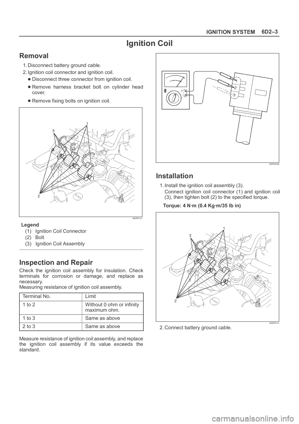
060RW121
Legend
(1) Ignition Coil Connector
(2) Bolt
(3) Ignition Coil Assembly
Inspection and Repair
Check the ignition coil assembly for insulation. Check
terminals for corrosion or damage, and replace as
necessary.
Measuring resistance of ignition coil assembly.
Terminal No.
Limit
1 to 2Without 0 ohm or infinity
maximum ohm.
1 to 3Same as above
2 to 3Same as above
Measure resistance of ignition coil assembly, and replace
the ignition coil assembly if its value exceeds the
standard.
060RW006
Installation
1. Install the ignition coil assembly (3).
Connect ignition coil connector (1) and ignition coil
(3), then tighten bolt (2) to the specified torque.
Torque: 4 Nꞏm (0.4 Kgꞏm/35 lb in)
060RW121
2. Connect battery ground cable.
Page 1089 of 6000
6D2–4
IGNITION SYSTEM
Spark Plug
Removal
1. Remove spark plugs.
Inspection and Repair
The spark plug affects entire engine performance and
therefore its inspection is very important.
Check electrode and insulator for presence of cracks,
and replace if any.
Check electrode for wear, and replace if necessary.
Check gasket for damage, and replace if necessary.
Measure insulation resistance with an ohmmeter, and
replace if faulty.
Adjust spark plug gap to 1.0 mm (0.04 in) 1.1 mm
(0.043 in).
Check fuel and electrical systems if spark plug is
extremely dirty.
Use spark plugs having low heat value (hot type plug)
if fuel and electrical systems are normal.
Use spark plugs having high heat value (cold type
plug) if insulator and electrode are extremely burned.
Sooty Spark Plugs
Much deposit of carbon or oil on the electrode and
insulator of spark plug reduces the engine performance.
Possible causes:
Too rich mixture
Presence of oil in combustion chamber
Incorrectly adjusted spark plug gap
Burning Electrodes
This fault is characterized by scorched or heavily oxidized
electrode or blistered insulator nose.
Possible causes:
Too lean mixture
Improper heat value
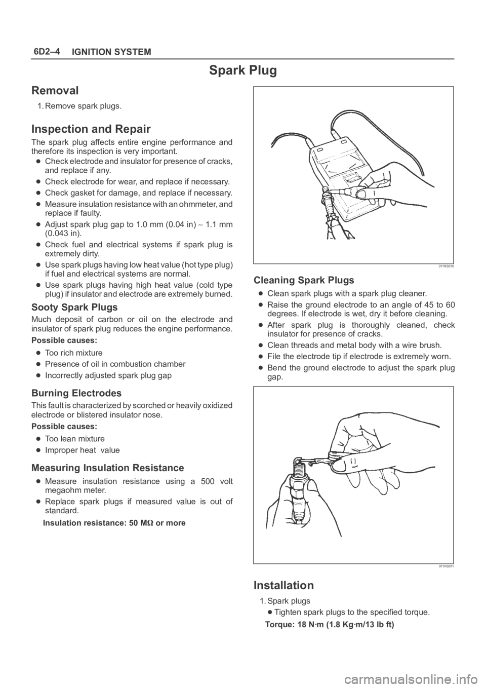
Measuring Insulation Resistance
Measure insulation resistance using a 500 volt
megaohm meter.
Replace spark plugs if measured value is out of
standard.
Insulation resistance: 50 M
or more
011RS010
Cleaning Spark Plugs
Clean spark plugs with a spark plug cleaner.
Raise the ground electrode to an angle of 45 to 60
degrees. If electrode is wet, dry it before cleaning.
After spark plug is thoroughly cleaned, check
insulator for presence of cracks.
Clean threads and metal body with a wire brush.
File the electrode tip if electrode is extremely worn.
Bend the ground electrode to adjust the spark plug
gap.
011RS011
Installation
1. Spark plugs
Tighten spark plugs to the specified torque.
Torque: 18 Nꞏm (1.8 Kgꞏm/13 lb ft)
Page 1102 of 6000
6D3–11 STARTING AND CHARGING SYSTEM
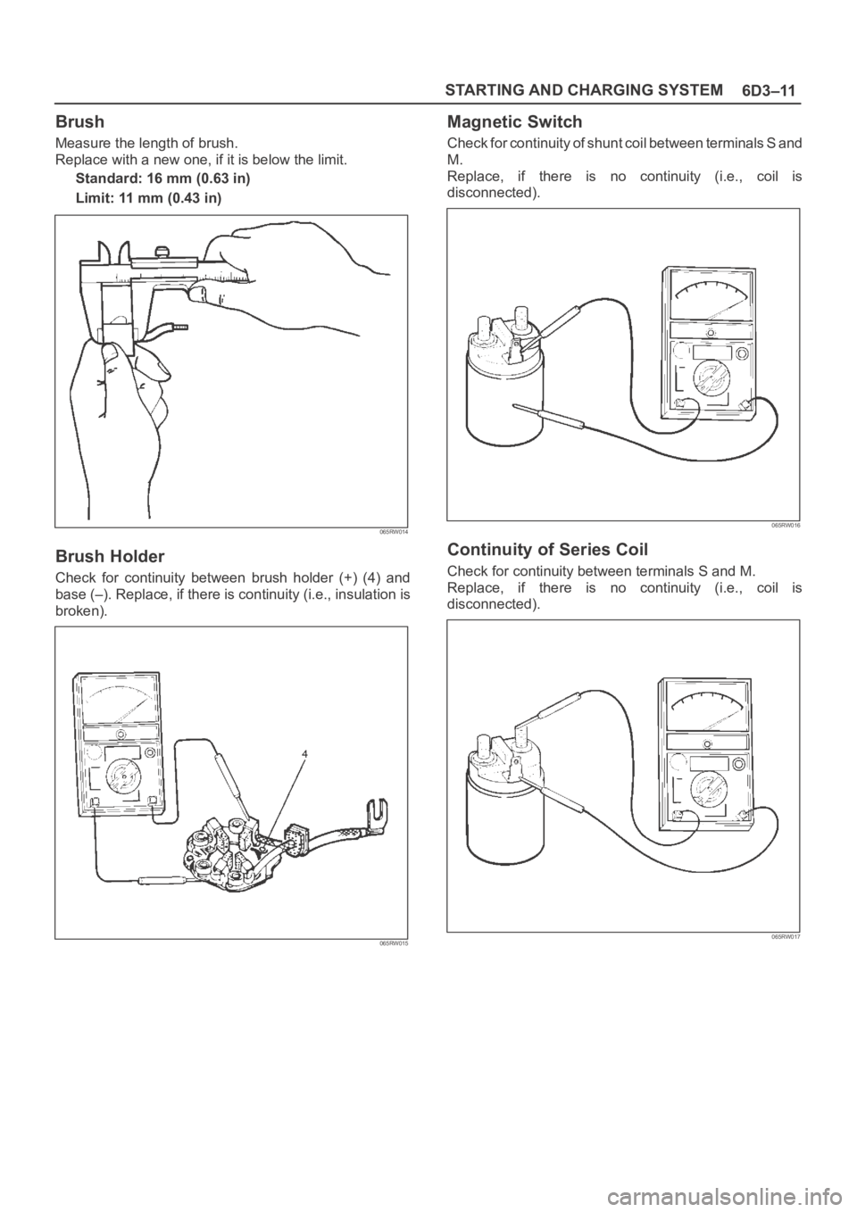
Brush
Measure the length of brush.
Replace with a new one, if it is below the limit.
Standard: 16 mm (0.63 in)
Limit: 11 mm (0.43 in)
065RW014
Brush Holder
Check for continuity between brush holder (+) (4) and
base (–). Replace, if there is continuity (i.e., insulation is
broken).
065RW015
Magnetic Switch
Check for continuity of shunt coil between terminals S and
M.
Replace, if there is no continuity (i.e., coil is
disconnected).
065RW016
Continuity of Series Coil
Check for continuity between terminals S and M.
Replace, if there is no continuity (i.e., coil is
disconnected).
065RW017
Page 1109 of 6000
6D3–18STARTING AND CHARGING SYSTEM
Charging System
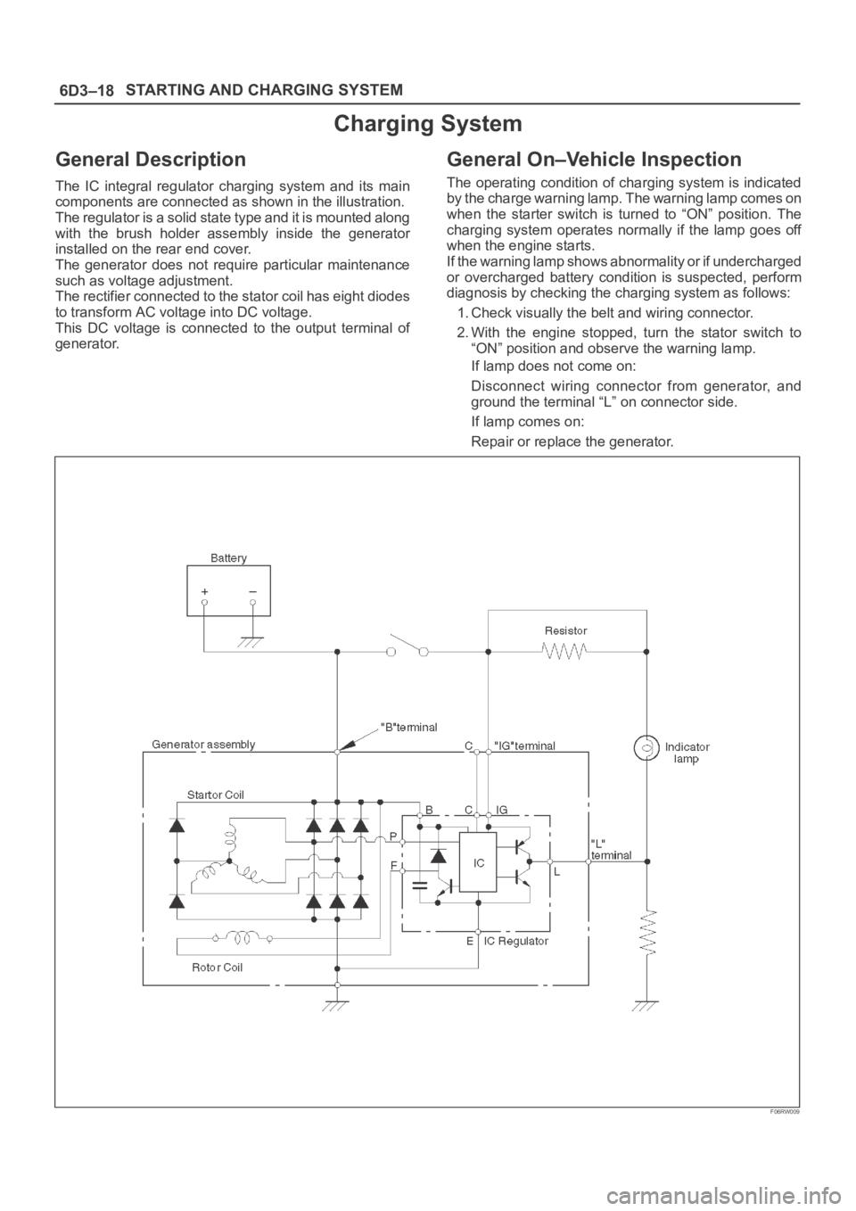
General Description
The IC integral regulator charging system and its main
components are connected as shown in the illustration.
The regulator is a solid state type and it is mounted along
with the brush holder assembly inside the generator
installed on the rear end cover.
The generator does not require particular maintenance
such as voltage adjustment.
The rectifier connected to the stator coil has eight diodes
to transform AC voltage into DC voltage.
This DC voltage is connected to the output terminal of
generator.
General On–Vehicle Inspection
The operating condition of charging system is indicated
by the charge warning lamp. The warning lamp comes on
when the starter switch is turned to “ON” position. The
charging system operates normally if the lamp goes off
when the engine starts.
If the warning lamp shows abnormality or if undercharged
or overcharged battery condition is suspected, perform
diagnosis by checking the charging system as follows:
1. Check visually the belt and wiring connector.
2. With the engine stopped, turn the stator switch to
“ON” position and observe the warning lamp.
If lamp does not come on:
Disconnect wiring connector from generator, and
ground the terminal “L” on connector side.
If lamp comes on:
Repair or replace the generator.
F06RW009
Page 1115 of 6000
6D3–24STARTING AND CHARGING SYSTEM
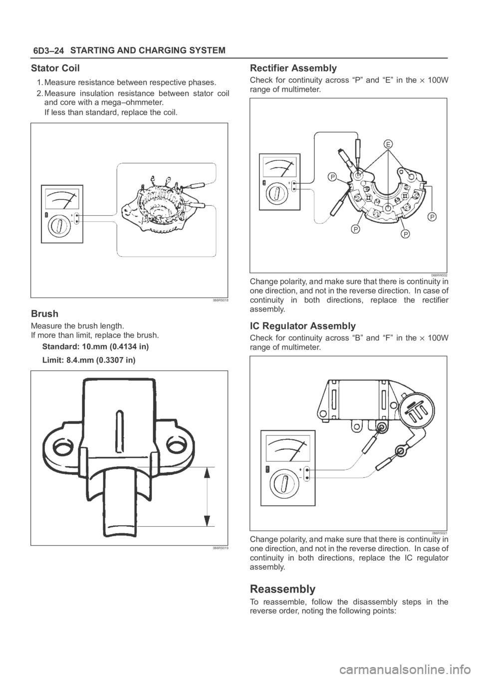
Stator Coil
1. Measure resistance between respective phases.
2. Measure insulation resistance between stator coil
and core with a mega–ohmmeter.
If less than standard, replace the coil.
066RS018
Brush
Measure the brush length.
If more than limit, replace the brush.
Standard: 10.mm (0.4134 in)
Limit: 8.4.mm (0.3307 in)
066RS019
Rectifier Assembly
Check for continuity across “P” and “E” in the 100W
range of multimeter.
066RW002Change polarity, and make sure that there is continuity in
one direction, and not in the reverse direction. In case of
continuity in both directions, replace the rectifier
assembly.
IC Regulator Assembly
Check for continuity across “B” and “F” in the 100W
range of multimeter.
066RS021Change polarity, and make sure that there is continuity in
one direction, and not in the reverse direction. In case of
continuity in both directions, replace the IC regulator
assembly.
Reassembly
To reassemble, follow the disassembly steps in the
reverse order, noting the following points:
Page 1119 of 6000
6E–2
ENGINE DRIVEABILITY AND EMISSIONS
Primary System-Based Diagnostic 6E–50. . . . . . . . .
Primary System-Based Diagnostic 6E–50. . . . . . .
Fuel Control Heated Oxygen Sensor 6E–50. . . . .
HO2S Heater 6E–50. . . . . . . . . . . . . . . . . . . . . . . . .
Fuel Trim System Monitor Diagnostic
Operation 6E–50. . . . . . . . . . . . . . . . . . . . . . . . . . . . . .
Fuel Trim System Monitor Diagnostic
Operation 6E–50. . . . . . . . . . . . . . . . . . . . . . . . . . . .
Fuel Trim Cell Diagnostic Weights 6E–50. . . . . . .
On-Board Diagnostic (OBD) System Check 6E–51.
A/C Clutch Control Circuit Diagnosis 6E–54. . . . . . .
Electronic Ignition System Diagnosis 6E–60. . . . . . .
Fuel Metering System Check 6E–60. . . . . . . . . . . . .
Idle Air Control (IAC) Valve 6E–60. . . . . . . . . . . . . . .
Fuel System Pressure Test 6E–60. . . . . . . . . . . . . . .
Fuel Injector Coil Test Procedure and Fuel
Injector Balance Test Procedure 6E–60. . . . . . . . . .
Knock Sensor Diagnosis 6E–65. . . . . . . . . . . . . . . . .
Powertrain Control Module (PCM) Diagnosis 6E–65
Multiple PCM Information Sensor DTCS Set 6E–65
Exhaust Gas Recirculation (EGR) Diagnosis
(For except EXPORT and
SOUTH AFRICA) 6E–68. . . . . . . . . . . . . . . . . . . . . . .
Engine Tech 2 Data Definitions and Ranges 6E–68
Typical Scan Data Values 6E–70. . . . . . . . . . . . . . . .
No Malfunction Indicator Lamp (MIL) 6E–74. . . . . . .
Malfunction Indicator Lamp (MIL) “ON”
Steady 6E–77. . . . . . . . . . . . . . . . . . . . . . . . . . . . . . . .
Engine Cranks But Will Not Run 6E–79. . . . . . . . . . .
Fuel System Electrical Test 6E–85. . . . . . . . . . . . . . .
Fuel System Diagnosis 6E–88. . . . . . . . . . . . . . . . . . .
Idle Air Control (IAC) System Check 6E–93. . . . . . .
Knock Sensor (KS) System Check
(Engine Knock, Poor Performance, or Poor
Economy) 6E–95. . . . . . . . . . . . . . . . . . . . . . . . . . . . .
Exhaust Gas Recirculation (EGR) System
Check 6E–97. . . . . . . . . . . . . . . . . . . . . . . . . . . . . . . . .
Manifold Absolute Pressure (MAP) Output
Check 6E–99. . . . . . . . . . . . . . . . . . . . . . . . . . . . . . . . .
PCM Diagnostic Trouble Codes 6E–101. . . . . . . . . . .
Diagnostic Trouble Code (DTC) P0101
MAF System Performance 6E–104. . . . . . . . . . . . . . .
Diagnostic Trouble Code (DTC) P0102
MAF Sensor Circuit Low Frequency 6E–107. . . . . .
Diagnostic Trouble Code (DTC) P0103
MAF Sensor Circuit High Frequency 6E–110. . . . . .
Diagnostic Trouble Code (DTC) P0107
MAP Sensor Circuit Low Voltage 6E–112. . . . . . . . . .
Diagnostic Trouble Code (DTC) P0108
MAP Sensor Circuit High Voltage 6E–115. . . . . . . . .
Diagnostic Trouble Code (DTC) P0112
IAT Sensor Circuit Low Voltage 6E–118. . . . . . . . . . .
Diagnostic Trouble Code (DTC) P0113
IAT Sensor Circuit High Voltage 6E–121. . . . . . . . . . Diagnostic Trouble Code (DTC) P0117
ECT Sensor Circuit Low Voltage 6E–124. . . . . . . . . .
Diagnostic Trouble Code (DTC) P0118
ECT Sensor Circuit High Voltage 6E–127. . . . . . . . .
Diagnostic Trouble Code (DTC) P0121
TP System Performance 6E–130. . . . . . . . . . . . . . . . .
Diagnostic Trouble Code (DTC) P0122
TP Sensor Circuit Low Voltage 6E–133. . . . . . . . . . .
Diagnostic Trouble Code (DTC) P0123
TP Sensor Circuit High Voltage 6E–136. . . . . . . . . .
Diagnostic Trouble Code (DTC) P0131
HO2S Circuit Low Voltage Bank 1
Sensor 1 6E–139. . . . . . . . . . . . . . . . . . . . . . . . . . . . . . .
Diagnostic Trouble Code (DTC) P0132
HO2S Circuit High Voltage Bank 1
Sensor 1 6E–142. . . . . . . . . . . . . . . . . . . . . . . . . . . . . . .
Diagnostic Trouble Code (DTC) P0134
HO2S Circuit Insufficient Activity Bank 1
Sensor 1 6E–145. . . . . . . . . . . . . . . . . . . . . . . . . . . . . .
Diagnostic Trouble Code (DTC) P0151
HO2S Circuit Low Voltage Bank 2
Sensor 1 6E–148. . . . . . . . . . . . . . . . . . . . . . . . . . . . . . .
Diagnostic Trouble Code (DTC) P0152
HO2S Circuit HIGH Voltage Bank 2
Sensor 1 6E–151. . . . . . . . . . . . . . . . . . . . . . . . . . . . . . .
Diagnostic Trouble Code (DTC) P0171
Fuel Trim System Lean Bank 1 6E–154. . . . . . . . . . .
Diagnostic Trouble Code (DTC) P0172
Fuel Trim System Rich Bank 1 6E–158. . . . . . . . . . .
Diagnostic Trouble Code (DTC) P0174
Fuel Trim System Lean Bank 2 6E–162. . . . . . . . . . .
Diagnostic Trouble Code (DTC) P0175
Fuel Trim System Rich Bank 2 6E–166. . . . . . . . . . .
Diagnostic Trouble Code (DTC) P0201
Injector 1 Control Circuit 6E–170. . . . . . . . . . . . . . . . .
Diagnostic Trouble Code (DTC) P0202
Injector 2 Control Circuit 6E–173. . . . . . . . . . . . . . . . .
Diagnostic Trouble Code (DTC) P0203
Injector 3 Control Circuit 6E–176. . . . . . . . . . . . . . . . .
Diagnostic Trouble Code (DTC) P0204
Injector 4 Control Circuit 6E–179. . . . . . . . . . . . . . . . .
Diagnostic Trouble Code (DTC) P0205
Injector 5 Control Circuit 6E–182. . . . . . . . . . . . . . . . .
Diagnostic Trouble Code (DTC) P0206
Injector 6 Control Circuit 6E–185. . . . . . . . . . . . . . . . .
Diagnostic Trouble Code (DTC) P0325
KS Module Circuit 6E–188. . . . . . . . . . . . . . . . . . . . . .
Diagnostic Trouble Code (DTC) P0327
KS Sensor Circuit 6E–190. . . . . . . . . . . . . . . . . . . . . . .
Diagnostic Trouble Code (DTC) P0336
58X Reference Signal Circuit 6E–193. . . . . . . . . . . . .
Diagnostic Trouble Code (DTC) P0337
CKP Sensor Circuit Low Frequency 6E–195. . . . . . .
Diagnostic Trouble Code (DTC) P0341
CMP Sensor Circuit Performance 6E–198. . . . . . . . .
Diagnostic Trouble Code (DTC) P0342
CMP Sensor Circuit Low 6E–202. . . . . . . . . . . . . . . . .
Page 1155 of 6000
6E–38
ENGINE DRIVEABILITY AND EMISSIONS
General Service Information
OBD Serviceablity Issues
The list of non-vehicle faults that could affect the
performance of the OBD system has been compiled.
These non-vehicle faults vary from environmental
conditions to the quality of fuel used.
The illumination of the MIL (“Check Engine” lamp) due to
a non-vehicle fault could lead to misdiagnosis of the
vehicle, increased warranty expense and customer
dissatisfaction. The following list of non-vehicle faults
does not include every possible fault and may not apply
equally to all product lines.
Fuel Quality
Using fuel with the wrong octane rating for your vehicle
may cause driveability problems. Many of the major fuel
companies advertise that using “premium” gasoline will
improve the performance of your vehicle. Most premium
fuels use alcohol to increase the octane rating of the fuel.
Although alcohol-enhanced fuels may raise the octane
rating, the fuel’s ability to turn into vapor in cold
temperatures deteriorates. This may affect the starting
ability and cold driveability of the engine.
Low fuel levels can lead to fuel starvation, lean engine
operation, and eventually engine misfire.
Non-OEM Parts
All of the OBD diagnostics have been calibrated to run
with OEM parts. Something as simple as a
high-performance exhaust system that affects exhaust
system back pressure could potentially interfere with the
operation of the EGR valve and thereby turn on the MIL
(“Check Engine” lamp). Small leaks in the exhaust
system near the post catalyst oxygen sensor can also
cause the MIL (“Check Engine” lamp) to turn on.
Aftermarket electronics, such as cellular phones,
stereos, and anti-theft devices, may radiate EMI into the
control system if they are improperly installed. This may
cause a false sensor reading and turn on the MIL (“Check
Engine” lamp).
Environment
Temporary environmental conditions, such as localized
flooding, will have an effect on the vehicle ignition system.
If the ignition system is rain-soaked, it can temporarily
cause engine misfire and turn on the MIL (“Check Engine”
lamp).
Poor Vehicle Maintenance
The sensitivity of OBD diagnostics will cause the MIL
(“Check Engine” lamp) to turn on if the vehicle is not
maintained properly. Restricted air filters, fuel filters, and
crankcase deposits due to lack of oil changes or improper
oil viscosity can trigger actual vehicle faults that were not
previously monitored prior to OBD. Poor vehicle
maintenance can not be classified as a “non-vehicle
fault”, but with the sensitivity of OBD diagnostics, vehicle
maintenance schedules must be more closely followed.Related System Faults
Many of the OBD system diagnostics will not run if the
PCM detects a fault on a related system or component.
One example would be that if the PCM detected a Misfire
fault, the diagnostics on the catalytic converter would be
suspended until Misfire fault was repaired. If the Misfire
fault was severe enough, the catalytic converter could be
damaged due to overheating and would never set a
Catalyst DTC until the Misfire fault was repaired and the
Catalyst diagnostic was allowed to run to completion. If
this happens, the customer may have to make two trips to
the dealership in order to repair the vehicle.
Maintenance Schedule
Refer to the Maintenance Schedule.
Visual / Physical Engine Compartment
Inspection
Perform a careful visual and physical engine
compartment inspection when performing any diagnostic
procedure or diagnosing the cause of an emission test
failure. This can often lead to repairing a problem without
further steps. Use the following guidelines when
performing a visual/physical inspection:
Inspect all vacuum hoses for punches, cuts,
disconnects, and correct routing.
Inspect hoses that are difficult to see behind other
components.
Inspect all wires in the engine compartment for proper
connections, burned or chafed spots, pinched wires,
contact with sharp edges or contact with hot exhaust
manifolds or pipes.
Basic Knowledge of Tools Required
NOTE: Lack of basic knowledge of this powertrain when
performing diagnostic procedures could result in an
incorrect diagnosis or damage to powertrain
components. Do not attempt to diagnose a powertrain
problem without this basic knowledge.
A basic understanding of hand tools is necessary to effec-
tively use this section of the Service Manual.
Serial Data Communications
Class II Serial Data Communications
This vehicle utilizes the “Class II” communication system.
Each bit of information can have one of two lengths: long
or short. This allows vehicle wiring to be reduced by
transmitting and receiving multiple signals over a single
wire. The messages carried on Class II data streams are
also prioritized. If two messages attempt to establish
communications on the data line at the same time, only
the message with higher priority will continue. The device
with the lower priority message must wait. The most
significant result of this regulation is that it provides Tech 2
manufacturers with the capability to access data from any
make or model vehicle that is sold.
Page 1171 of 6000
6E–54
ENGINE DRIVEABILITY AND EMISSIONS
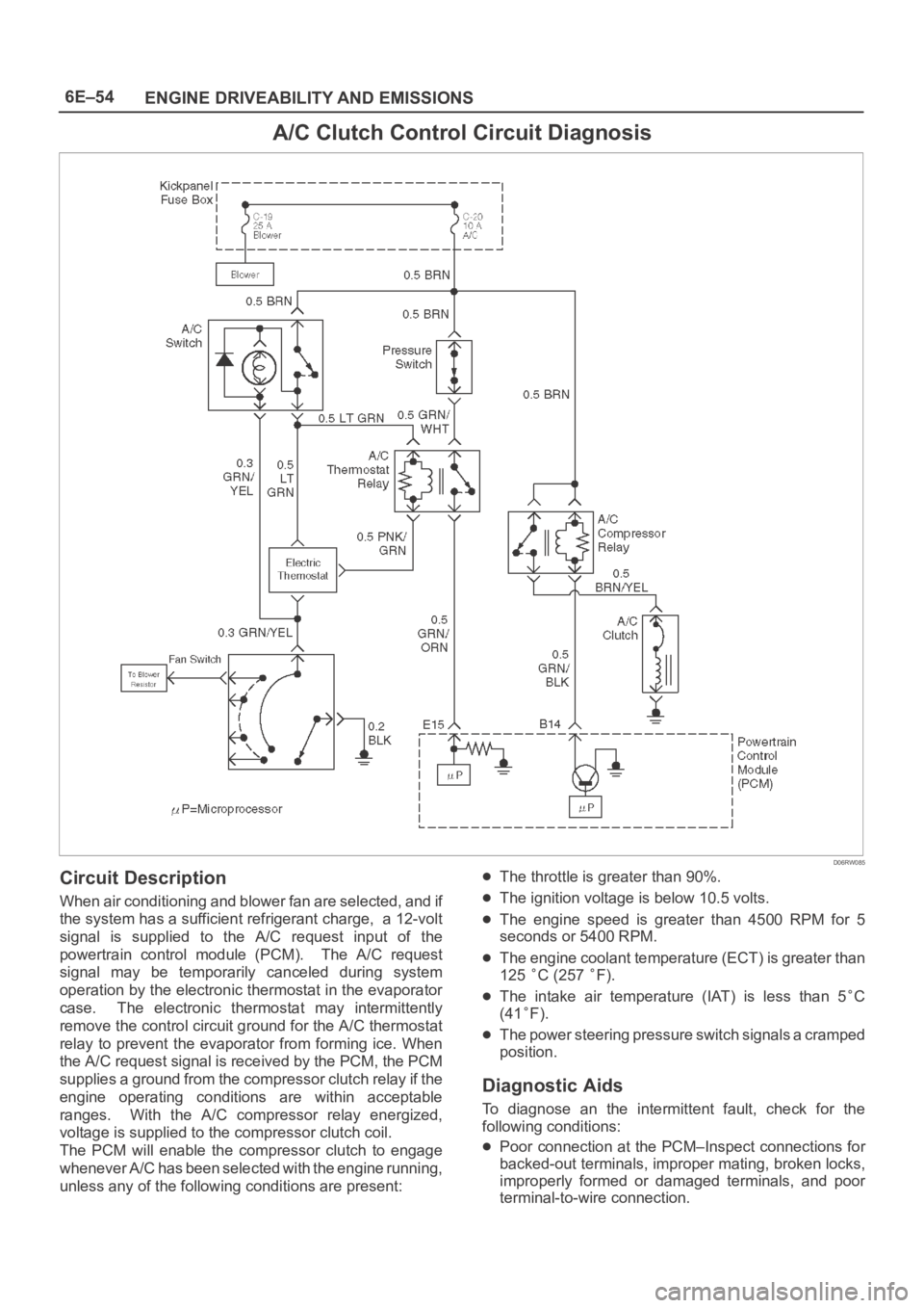
A/C Clutch Control Circuit Diagnosis
D06RW085
Circuit Description
When air conditioning and blower fan are selected, and if
the system has a sufficient refrigerant charge, a 12-volt
signal is supplied to the A/C request input of the
powertrain control module (PCM). The A/C request
signal may be temporarily canceled during system
operation by the electronic thermostat in the evaporator
case. The electronic thermostat may intermittently
remove the control circuit ground for the A/C thermostat
relay to prevent the evaporator from forming ice. When
the A/C request signal is received by the PCM, the PCM
supplies a ground from the compressor clutch relay if the
engine operating conditions are within acceptable
ranges. With the A/C compressor relay energized,
voltage is supplied to the compressor clutch coil.
The PCM will enable the compressor clutch to engage
whenever A/C has been selected with the engine running,
unless any of the following conditions are present:
The throttle is greater than 90%.
The ignition voltage is below 10.5 volts.
The engine speed is greater than 4500 RPM for 5
seconds or 5400 RPM.
The engine coolant temperature (ECT) is greater than
125
C (257 F).
The intake air temperature (IAT) is less than 5C
(41
F).
The power steering pressure switch signals a cramped
position.
Diagnostic Aids
To diagnose an the intermittent fault, check for the
following conditions:
Poor connection at the PCM–Inspect connections for
backed-out terminals, improper mating, broken locks,
improperly formed or damaged terminals, and poor
terminal-to-wire connection.