Page 2383 of 6000
MANUAL TRANSMISSION7B–65
2. Using a pin punch and hammer, drive in the
slotted spring pin (2) to the shift lever housing.
NOTE: Be carefull not to drop the slotted spring pin.
230RW002
3. Apply sealant (THREE BOND 1344 or
equivalent) to the plug (1) thread.
4. Using hexagon wrench, install and torque the
plug (1).
Torque: 18 Nꞏm (1.8 kgꞏm/13 lb ft)
220RW010
5. Clean up the bolts and bolt hole.
6. Using 6 bolts, install the gear control box through
the gasket.
Torque 18 Nꞏm (1.8 kgꞏm/13 lb ft)
(6VE1)
230RW001
(4JX1)
220RW097
Page 2384 of 6000

7B–66MANUAL TRANSMISSION
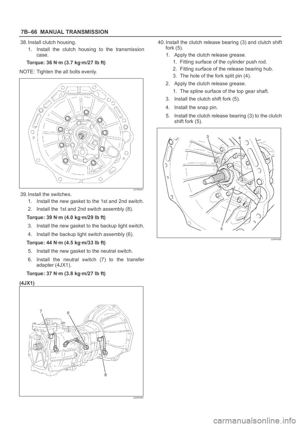
38. Install clutch housing.
1. Install the clutch housing to the transmission
case.
Torque: 36 Nꞏm (3.7 kgꞏm/27 lb ft)
NOTE: Tighten the all bolts evenly.
241RW001
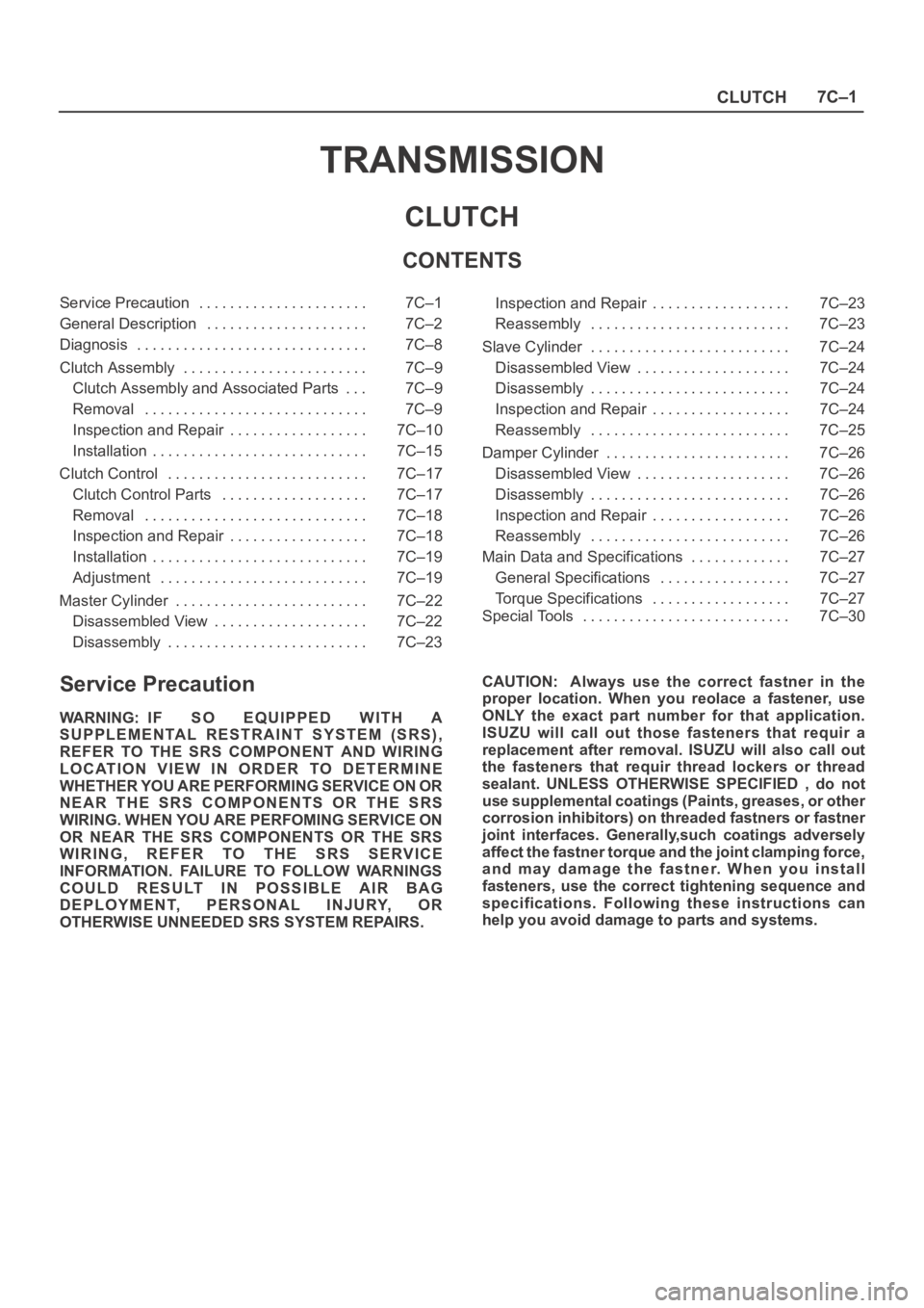
39. Install the switches.
1. Install the new gasket to the 1st and 2nd switch.
2. Install the 1st and 2nd switch assembly (8).
Torque: 39 Nꞏm (4.0 kgꞏm/29 lb ft)
3. Install the new gasket to the backup light switch.
4. Install the backup light switch assembly (6).
Torque: 44 Nꞏm (4.5 kgꞏm/33 lb ft)
5. Install the new gasket to the neutral switch.
6. Install the neutral switch (7) to the transfer
adapter (4JX1).
Torque: 37 Nꞏm (3.8 kgꞏm/27 lb ft)
(4JX1)
220RW093
40. Install the clutch release bearing (3) and clutch shift
fork (5).
1. Apply the clutch release grease.
1. Fitting surface of the cylinder push rod.
2. Fitting surface of the release bearing hub.
3. The hole of the fork split pin (4).
2. Apply the clutch release grease.
1. The spline surface of the top gear shaft.
3. Install the clutch shift fork (5).
4. Install the snap pin.
5. Install the clutch release bearing (3) to the clutch
shift fork (5).
220RW086
Page 2385 of 6000
MANUAL TRANSMISSION7B–67
41. Install the drain plug and filler plug.
1. Install the drain plug (1) through the new gasket.
Torque: 37 Nꞏm (3.8 kgꞏm/27 lb ft)
2. Install the filler plug (2) through the new gasket.
Reference: Plug after the gear oil fill in.
Torque: 37 Nꞏm (3.8 kgꞏm/27 lb ft)
(6VE1)
220RW007
Page 2387 of 6000
MANUAL TRANSMISSION7B–69
Torque Specifications
E07RW049
Page 2388 of 6000
7B–70MANUAL TRANSMISSION
Torque Specifications (Cont’d)
E07RW050
Page 2389 of 6000
MANUAL TRANSMISSION7B–71
Torque Specifications (Cont’d)
E07RW051
Page 2511 of 6000

CLUTCH7C–1
TRANSMISSION
CLUTCH
CONTENTS
Service Precaution 7C–1. . . . . . . . . . . . . . . . . . . . . .
General Description 7C–2. . . . . . . . . . . . . . . . . . . . .
Diagnosis 7C–8. . . . . . . . . . . . . . . . . . . . . . . . . . . . . .
Clutch Assembly 7C–9. . . . . . . . . . . . . . . . . . . . . . . .
Clutch Assembly and Associated Parts 7C–9. . .
Removal 7C–9. . . . . . . . . . . . . . . . . . . . . . . . . . . . .
Inspection and Repair 7C–10. . . . . . . . . . . . . . . . . .
Installation 7C–15. . . . . . . . . . . . . . . . . . . . . . . . . . . .
Clutch Control 7C–17. . . . . . . . . . . . . . . . . . . . . . . . . .
Clutch Control Parts 7C–17. . . . . . . . . . . . . . . . . . .
Removal 7C–18. . . . . . . . . . . . . . . . . . . . . . . . . . . . .
Inspection and Repair 7C–18. . . . . . . . . . . . . . . . . .
Installation 7C–19. . . . . . . . . . . . . . . . . . . . . . . . . . . .
Adjustment 7C–19. . . . . . . . . . . . . . . . . . . . . . . . . . .
Master Cylinder 7C–22. . . . . . . . . . . . . . . . . . . . . . . . .
Disassembled View 7C–22. . . . . . . . . . . . . . . . . . . .
Disassembly 7C–23. . . . . . . . . . . . . . . . . . . . . . . . . . Inspection and Repair 7C–23. . . . . . . . . . . . . . . . . .
Reassembly 7C–23. . . . . . . . . . . . . . . . . . . . . . . . . .
Slave Cylinder 7C–24. . . . . . . . . . . . . . . . . . . . . . . . . .
Disassembled View 7C–24. . . . . . . . . . . . . . . . . . . .
Disassembly 7C–24. . . . . . . . . . . . . . . . . . . . . . . . . .
Inspection and Repair 7C–24. . . . . . . . . . . . . . . . . .
Reassembly 7C–25. . . . . . . . . . . . . . . . . . . . . . . . . .
Damper Cylinder 7C–26. . . . . . . . . . . . . . . . . . . . . . . .
Disassembled View 7C–26. . . . . . . . . . . . . . . . . . . .
Disassembly 7C–26. . . . . . . . . . . . . . . . . . . . . . . . . .
Inspection and Repair 7C–26. . . . . . . . . . . . . . . . . .
Reassembly 7C–26. . . . . . . . . . . . . . . . . . . . . . . . . .
Main Data and Specifications 7C–27. . . . . . . . . . . . .
General Specifications 7C–27. . . . . . . . . . . . . . . . .
Torque Specifications 7C–27. . . . . . . . . . . . . . . . . .
Special Tools 7C–30. . . . . . . . . . . . . . . . . . . . . . . . . . .
Service Precaution
WARNING: IF SO EQUIPPED WITH A
SUPPLEMENTAL RESTRAINT SYSTEM (SRS),
REFER TO THE SRS COMPONENT AND WIRING
LOCATION VIEW IN ORDER TO DETERMINE
WHETHER YOU ARE PERFORMING SERVICE ON OR
NEAR THE SRS COMPONENTS OR THE SRS
WIRING. WHEN YOU ARE PERFOMING SERVICE ON
OR NEAR THE SRS COMPONENTS OR THE SRS
WIRING, REFER TO THE SRS SERVICE
INFORMATION. FAILURE TO FOLLOW WARNINGS
COULD RESULT IN POSSIBLE AIR BAG
DEPLOYMENT, PERSONAL INJURY, OR
OTHERWISE UNNEEDED SRS SYSTEM REPAIRS. CAUTION: Always use the correct fastner in the
proper location. When you reolace a fastener, use
ONLY the exact part number for that application.
ISUZU will call out those fasteners that requir a
replacement after removal. ISUZU will also call out
the fasteners that requir thread lockers or thread
sealant. UNLESS OTHERWISE SPECIFIED , do not
use supplemental coatings (Paints, greases, or other
corrosion inhibitors) on threaded fastners or fastner
joint interfaces. Generally,such coatings adversely
affect the fastner torque and the joint clamping force,
and may damage the fastner. When you install
fasteners, use the correct tightening sequence and
specifications. Following these instructions can
help you avoid damage to parts and systems.
Page 2524 of 6000

CLUTCH7C–15
Installation
To install, follow the removal steps in the reverse order,
noting the following points:
1. Install flywheel assembly and crankshaft bearing.
Use the installer 5-8840-0125-0 (J-26516-A) and
driver handle 5-8840-0007-0 (J-8092) to install the
crankshaft bearing then clean and lubricate with
grease.
015RW054
2. Install new flywheel fixing bolts in the order illustrated
and tighten them to the specified torque.
Torque:
6VE1: 54 Nꞏm (5.5 kgꞏm/40 lb ft)
4JX1: 60 Nꞏm (6.1 kgꞏm/44 lb ft)+60
NOTE: Do not reuse the bolt and do not apply oil or thread
lock to the bolt.
015RS047
3. Install the front cover (5) to the transmission case.
4. Tighten eight front cover bolts to the specified torque.
Torque: 17 Nꞏm (1.7 kgꞏm/12 lb ft)
220RW088
5. Apply molybednum disulfide type grease to the pin
hole inner circumferences and thrust surfaces.
6. Attach the shift fork to the front cover and insert the
pin from below of the front cover.
7. Install the washer and snap pin.
201RW019