1998 OPEL FRONTERA torque
[x] Cancel search: torquePage 2255 of 6000
7A1–10
TRANSMISSION CONTROL SYSTEM (4L30–E)
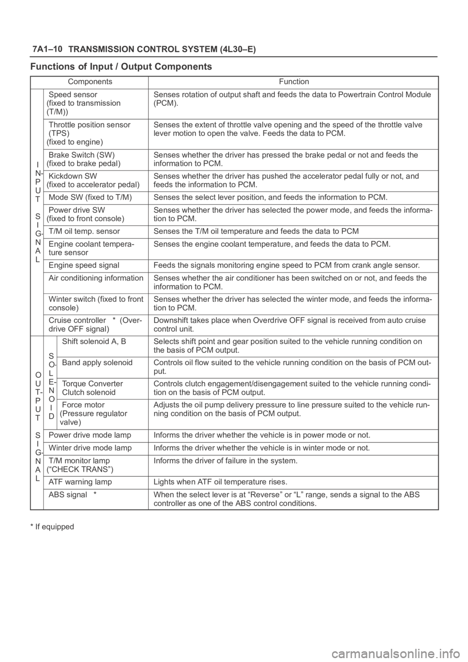
Functions of Input / Output Components
ComponentsFunction
Speed sensor
(fixed to transmission
(T/M))Senses rotation of output shaft and feeds the data to Powertrain Control Module
(PCM).
Throttle position sensor
(TPS)
(fixed to engine)Senses the extent of throttle valve opening and the speed of the throttle valve
lever motion to open the valve. Feeds the data to PCM.
I
N
Brake Switch (SW)
(fixed to brake pedal)Senses whether the driver has pressed the brake pedal or not and feeds the
information to PCM.
N-
P
U
Kickdown SW
(fixed to accelerator pedal)Senses whether the driver has pushed the accelerator pedal fully or not, and
feeds the information to PCM.
U
TMode SW (fixed to T/M)Senses the select lever position, and feeds the information to PCM.
S
I
Power drive SW
(fixed to front console)Senses whether the driver has selected the power mode, and feeds the informa-
tion to PCM.
I
G-T/M oil temp. sensorSenses the T/M oil temperature and feeds the data to PCM
N
A
L
Engine coolant tempera-
ture sensorSenses the engine coolant temperature, and feeds the data to PCM.
LEngine speed signalFeeds the signals monitoring engine speed to PCM from crank angle sensor.
Air conditioning informationSenses whether the air conditioner has been switched on or not, and feeds the
information to PCM.
Winter switch (fixed to front
console)Senses whether the driver has selected the winter mode, and feeds the informa-
tion to PCM.
Cruise controller * (Over-
drive OFF signal)Downshift takes place when Overdrive OFF signal is received from auto cruise
control unit.
S
Shift solenoid A, BSelects shift point and gear position suited to the vehicle running condition on
the basis of PCM output.
O
S
O-
L
Band apply solenoidControls oil flow suited to the vehicle running condition on the basis of PCM out-
put.
O
U
T-
P
E-
N
O
Torque Converter
Clutch solenoidControls clutch engagement/disengagement suited to the vehicle running condi-
tion on the basis of PCM output.
P
U
T
O
I
DForce motor
(Pressure regulator
valve)Adjusts the oil pump delivery pressure to line pressure suited to the vehicle run-
ning condition on the basis of PCM output.
S
I
Power drive mode lampInforms the driver whether the vehicle is in power mode or not.
I
G-Winter drive mode lampInforms the driver whether the vehicle is in winter mode or not.G
N
A
L
T/M monitor lamp
(“CHECK TRANS”)Informs the driver of failure in the system.
LATF warning lampLights when ATF oil temperature rises.
ABS signal *When the select lever is at “Reverse” or “L” range, sends a signal to the ABS
controller as one of the ABS control conditions.
* If equipped
Page 2266 of 6000
TRANSMISSION CONTROL SYSTEM (4L30–E)7A1–21
NOTE: To use the DTC again to identify a problem, you
will need to reproduce the fault or the problem. This may
require a new test drive or just turning the ignition on (this
depends on the nature of the fault).
1. IF you have a Tech2:
1. Connect the Tech2 if it is still not connected
GOTHROUGH Tech2 OBD II CONNECTION.
2. Push “F4” and answer “Yes” to the question “Do
you really want to clear the codes?”
a. When a malfunction remains as it is the Tech2
displays “4L30E CODES NOT CLEARED”. This
means that the problem is still there or that the
recovery was not done. Please GOTO DTC
CHECK.
b. When a malfunction has been repaired and the
recovery is done. The Tech2 displays “4L30E
CODES CLEARED”.
2. IF you have no Tech2:
To clear the DTC, remove Fuse “Stop, A/T CONT”
(C–14, 15A) for at least 10 seconds.
DTC Check
1. Diagnostic Trouble Codes (DTC) have been identified
by Tech2.
2. You have written the list of the DTCs. The order of the
malfunctions has no meanings for this PCM. Usually
only one or two malfunctions should be set for a given
problem.
3. Check directly the DTCs you identified. The DTCs are
sorted by number. Refer to Diagnostic Trouble Code
(DTC) Identification in this section.
PCM Precaution
The PCM can be damaged by:
1. Electrostatic discharge
2. The short circuit of some terminals to voltage or to
ground.
Electrostatic Discharge Damage Description:
1. Electronic components used to control systems are
often designed to carry very low voltage, and are very
susceptible to damage caused by electrostatic
discharge. It is possible for less than 100 volts of
static electricity to cause damage to some electronic
components. By comparison, it takes as much as
4,000 volts for a person to even feel the zap of a static
discharge.2. There are several ways for a person to become
statically charged. The most common methods of
charging are by friction and induction. An example of
charging by friction is a person sliding across a car
seat, in which a charge of as much as 25,000 volts
can build up. Charging by induction occurs when a
person with well insulated shoes stands near a highly
charged object and momentarily touches ground.
Charges for the same polarity are drained off, leaving
the person highly charged with the opposite polarity.
Static charges of either type can cause damage,
therefore, it is important to use care when handling
and testing electronic components.
NOTICE: To prevent possible electrostatic
discharge damage:
1. Do not touch the PCM connector pins or soldered
components on the PCM circuit board.
2. Be sure to follow the guidelines listed below if
servicing any of these electronic components:
3. Do not open the replacement part package until it is
time to install the part.
4. Avoid touching electrical terminals of the part.
5. Before removing the part from its package, ground
the package to a known good ground on the vehicle.
6. Always touch a known good ground before handling
the part. This step should be repeated before
installing the part if the part has been handled while
sliding across the seat, while sitting down from a
standing position or while walking some distance.
Information On PCM
1. The Powertrain Control Module (PCM) is located in
the center console and is the control center of the
electronic transmission control system.
2. The PCM must be maintained at a temperature below
185
F (85C) at all times. This is most essential if the
vehicle is put through a paint baking process. The
PCM will become inoperative if its temperature
exceeds 85
C (185F). Therefore, it is
recommended that the PCM be removed or that
temporary insulation be placed around the PCM
during the time the vehicle is in a paint oven or other
high temperature process.
3. The PCM is designed to process the various inputs
and then respond by sending the appropriate
electrical signals to control transmission upshift,
downshift, shift feel and torque converter clutch
engagement.
4. The PCM constantly interprets information from the
various sensors, and controls the systems that affect
transmission and vehicle performance. By analyzing
operational problems, the PCM is able to perform a
diagnostic function by displaying DTC(s) and aid the
technician in making repairs.
Intermittent Conditions
If the Tech2 displays a diagnostic trouble code as
intermittent, or if after a test drive a DTC does not
reappear though the detection conditions for this DTC are
present, the problem is most likely a faulty electrical
Page 2270 of 6000
TRANSMISSION CONTROL SYSTEM (4L30–E)7A1–25
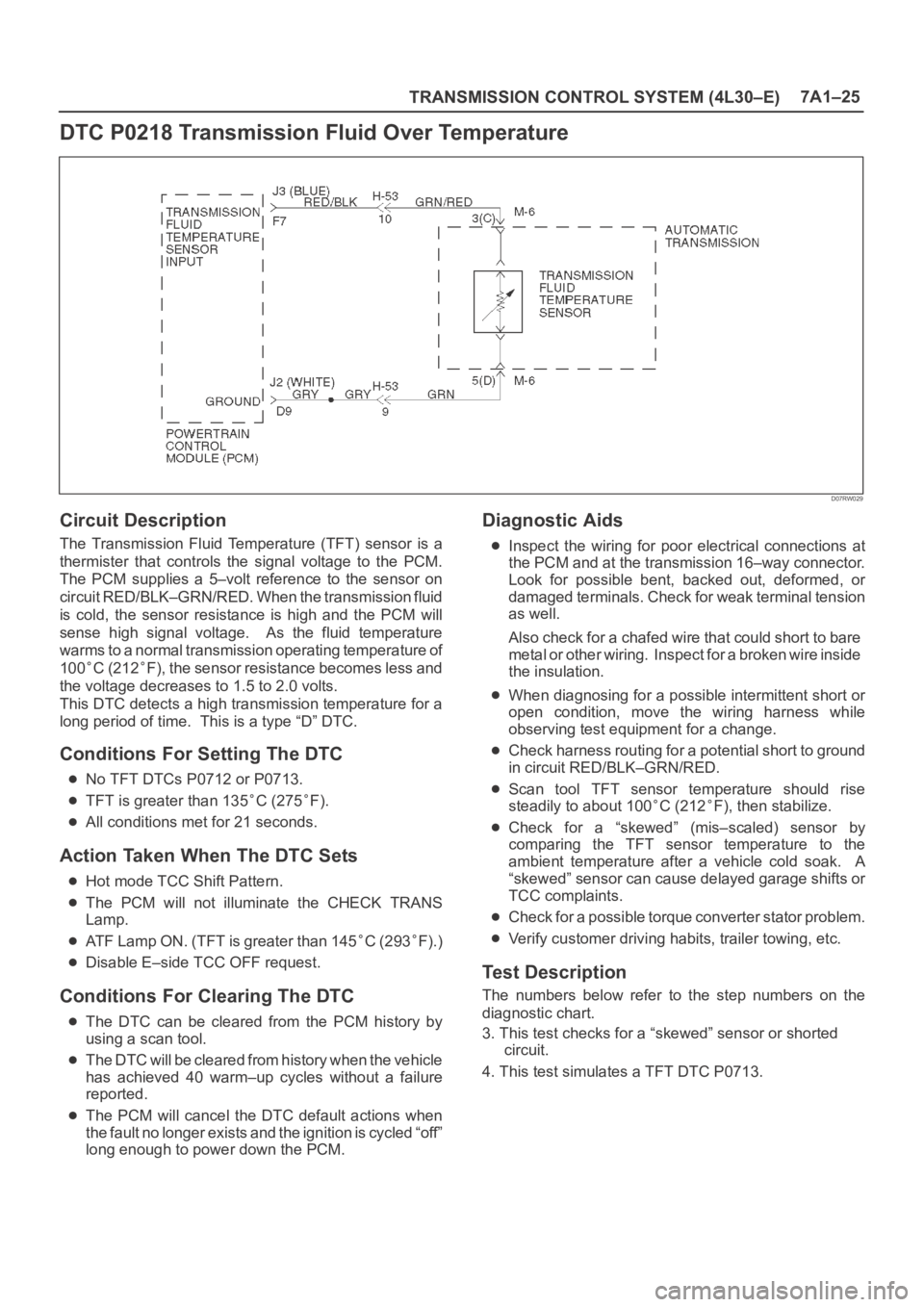
DTC P0218 Transmission Fluid Over Temperature
D07RW029
Circuit Description
The Transmission Fluid Temperature (TFT) sensor is a
thermister that controls the signal voltage to the PCM.
The PCM supplies a 5–volt reference to the sensor on
circuit RED/BLK–GRN/RED. When the transmission fluid
is cold, the sensor resistance is high and the PCM will
sense high signal voltage. As the fluid temperature
warms to a normal transmission operating temperature of
100
C (212F), the sensor resistance becomes less and
the voltage decreases to 1.5 to 2.0 volts.
This DTC detects a high transmission temperature for a
long period of time. This is a type “D” DTC.
Conditions For Setting The DTC
No TFT DTCs P0712 or P0713.
TFT is greater than 135C (275F).
All conditions met for 21 seconds.
Action Taken When The DTC Sets
Hot mode TCC Shift Pattern.
The PCM will not illuminate the CHECK TRANS
Lamp.
ATF Lamp ON. (TFT is greater than 145C (293F).)
Disable E–side TCC OFF request.
Conditions For Clearing The DTC
The DTC can be cleared from the PCM history by
using a scan tool.
The DTC will be cleared from history when the vehicle
has achieved 40 warm–up cycles without a failure
reported.
The PCM will cancel the DTC default actions when
the fault no longer exists and the ignition is cycled “off”
long enough to power down the PCM.
Diagnostic Aids
Inspect the wiring for poor electrical connections at
the PCM and at the transmission 16–way connector.
Look for possible bent, backed out, deformed, or
damaged terminals. Check for weak terminal tension
as well.
Also check for a chafed wire that could short to bare
metal or other wiring. Inspect for a broken wire inside
the insulation.
When diagnosing for a possible intermittent short or
open condition, move the wiring harness while
observing test equipment for a change.
Check harness routing for a potential short to ground
in circuit RED/BLK–GRN/RED.
Scan tool TFT sensor temperature should rise
steadily to about 100
C (212F), then stabilize.
Check for a “skewed” (mis–scaled) sensor by
comparing the TFT sensor temperature to the
ambient temperature after a vehicle cold soak. A
“skewed” sensor can cause delayed garage shifts or
TCC complaints.
Check for a possible torque converter stator problem.
Verify customer driving habits, trailer towing, etc.
Test Description
The numbers below refer to the step numbers on the
diagnostic chart.
3. This test checks for a “skewed” sensor or shorted
circuit.
4. This test simulates a TFT DTC P0713.
Page 2275 of 6000
7A1–30
TRANSMISSION CONTROL SYSTEM (4L30–E)
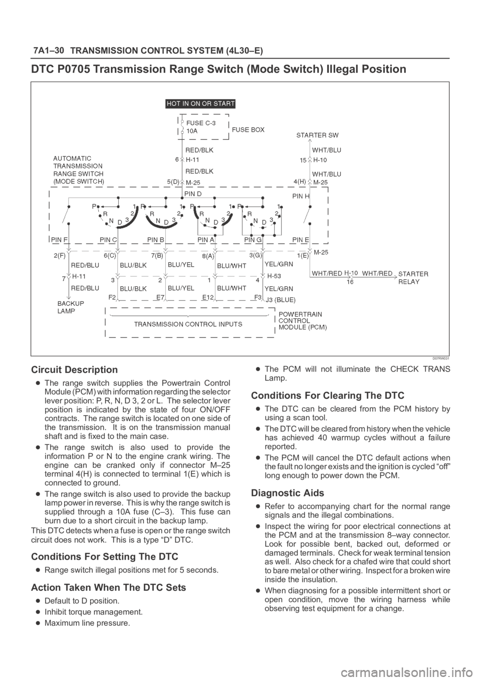
DTC P0705 Transmission Range Switch (Mode Switch) Illegal Position
D07RW031
Circuit Description
The range switch supplies the Powertrain Control
Module (PCM) with information regarding the selector
lever position: P, R, N, D 3, 2 or L. The selector lever
position is indicated by the state of four ON/OFF
contracts. The range switch is located on one side of
the transmission. It is on the transmission manual
shaft and is fixed to the main case.
The range switch is also used to provide the
information P or N to the engine crank wiring. The
engine can be cranked only if connector M–25
terminal 4(H) is connected to terminal 1(E) which is
connected to ground.
The range switch is also used to provide the backup
lamp power in reverse. This is why the range switch is
supplied through a 10A fuse (C–3). This fuse can
burn due to a short circuit in the backup lamp.
This DTC detects when a fuse is open or the range switch
circuit does not work. This is a type “D” DTC.
Conditions For Setting The DTC
Range switch illegal positions met for 5 seconds.
Action Taken When The DTC Sets
Default to D position.
Inhibit torque management.
Maximum line pressure.
The PCM will not illuminate the CHECK TRANS
Lamp.
Conditions For Clearing The DTC
The DTC can be cleared from the PCM history by
using a scan tool.
The DTC will be cleared from history when the vehicle
has achieved 40 warmup cycles without a failure
reported.
The PCM will cancel the DTC default actions when
the fault no longer exists and the ignition is cycled “off”
long enough to power down the PCM.
Diagnostic Aids
Refer to accompanying chart for the normal range
signals and the illegal combinations.
Inspect the wiring for poor electrical connections at
the PCM and at the transmission 8–way connector.
Look for possible bent, backed out, deformed or
damaged terminals. Check for weak terminal tension
as we ll. A lso ch eck fo r a ch af e d w ire th at cou l d s ho r t
to bare metal or other wiring. Inspect for a broken wire
inside the insulation.
When diagnosing for a possible intermittent short or
open condition, move the wiring harness while
observing test equipment for a change.
Page 2311 of 6000
7A1–66
TRANSMISSION CONTROL SYSTEM (4L30–E)
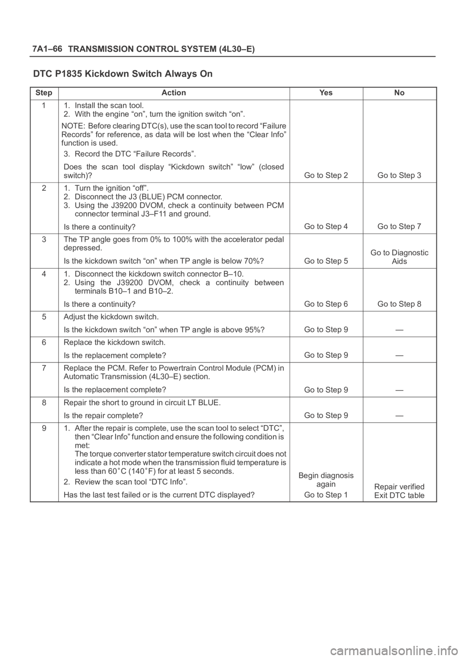
DTC P1835 Kickdown Switch Always On
StepActionYe sNo
11. Install the scan tool.
2. With the engine “on”, turn the ignition switch “on”.
NOTE: Before clearing DTC(s), use the scan tool to record “Failure
Records” for reference, as data will be lost when the “Clear Info”
function is used.
3. Record the DTC “Failure Records”.
Does the scan tool display “Kickdown switch” “low” (closed
switch)?
Go to Step 2Go to Step 3
21. Turn the ignition “off”.
2. Disconnect the J3 (BLUE) PCM connector.
3. Using the J39200 DVOM, check a continuity between PCM
connector terminal J3–F11 and ground.
Is there a continuity?
Go to Step 4Go to Step 7
3The TP angle goes from 0% to 100% with the accelerator pedal
depressed.
Is the kickdown switch “on” when TP angle is below 70%?
Go to Step 5
Go to Diagnostic
Aids
41. Disconnect the kickdown switch connector B–10.
2. Using the J39200 DVOM, check a continuity between
terminals B10–1 and B10–2.
Is there a continuity?
Go to Step 6Go to Step 8
5Adjust the kickdown switch.
Is the kickdown switch “on” when TP angle is above 95%?
Go to Step 9—
6Replace the kickdown switch.
Is the replacement complete?
Go to Step 9—
7Replace the PCM. Refer to Powertrain Control Module (PCM) in
Automatic Transmission (4L30–E) section.
Is the replacement complete?
Go to Step 9—
8Repair the short to ground in circuit LT BLUE.
Is the repair complete?
Go to Step 9—
91. After the repair is complete, use the scan tool to select “DTC”,
then “Clear Info” function and ensure the following condition is
met:
The torque converter stator temperature switch circuit does not
indicate a hot mode when the transmission fluid temperature is
less than 60
C (140F) for at least 5 seconds.
2. Review the scan tool “DTC Info”.
Has the last test failed or is the current DTC displayed?Begin diagnosis
again
Go to Step 1
Repair verified
Exit DTC table
Page 2316 of 6000
TRANSMISSION CONTROL SYSTEM (4L30–E)7A1–71
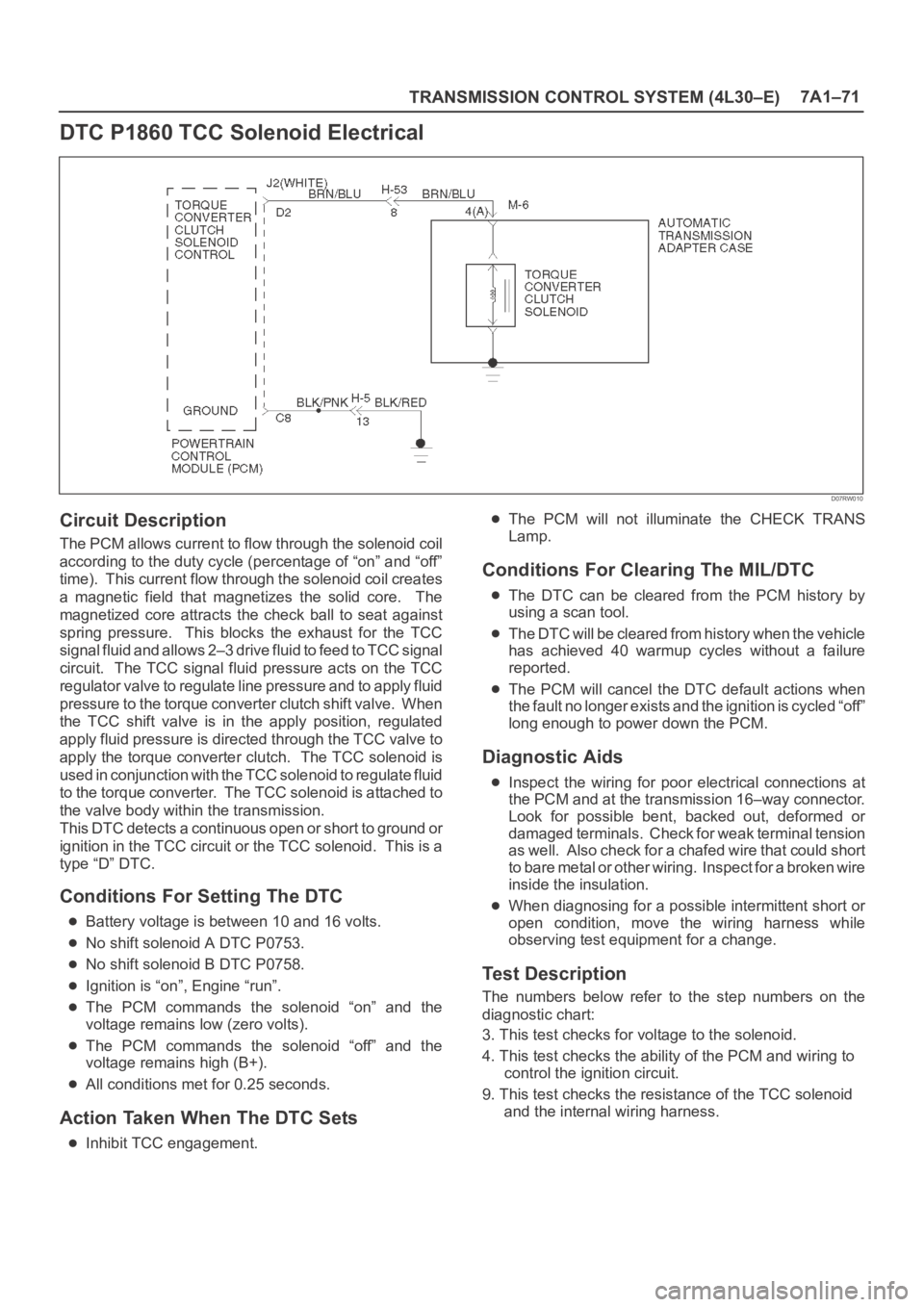
DTC P1860 TCC Solenoid Electrical
D07RW010
Circuit Description
The PCM allows current to flow through the solenoid coil
according to the duty cycle (percentage of “on” and “off”
time). This current flow through the solenoid coil creates
a magnetic field that magnetizes the solid core. The
magnetized core attracts the check ball to seat against
spring pressure. This blocks the exhaust for the TCC
signal fluid and allows 2–3 drive fluid to feed to TCC signal
circuit. The TCC signal fluid pressure acts on the TCC
regulator valve to regulate line pressure and to apply fluid
pressure to the torque converter clutch shift valve. When
the TCC shift valve is in the apply position, regulated
apply fluid pressure is directed through the TCC valve to
apply the torque converter clutch. The TCC solenoid is
used in conjunction with the TCC solenoid to regulate fluid
to the torque converter. The TCC solenoid is attached to
the valve body within the transmission.
This DTC detects a continuous open or short to ground or
ignition in the TCC circuit or the TCC solenoid. This is a
type “D” DTC.
Conditions For Setting The DTC
Battery voltage is between 10 and 16 volts.
No shift solenoid A DTC P0753.
No shift solenoid B DTC P0758.
Ignition is “on”, Engine “run”.
The PCM commands the solenoid “on” and the
voltage remains low (zero volts).
The PCM commands the solenoid “off” and the
voltage remains high (B+).
All conditions met for 0.25 seconds.
Action Taken When The DTC Sets
Inhibit TCC engagement.
The PCM will not illuminate the CHECK TRANS
Lamp.
Conditions For Clearing The MIL/DTC
The DTC can be cleared from the PCM history by
using a scan tool.
The DTC will be cleared from history when the vehicle
has achieved 40 warmup cycles without a failure
reported.
The PCM will cancel the DTC default actions when
the fault no longer exists and the ignition is cycled “off”
long enough to power down the PCM.
Diagnostic Aids
Inspect the wiring for poor electrical connections at
the PCM and at the transmission 16–way connector.
Look for possible bent, backed out, deformed or
damaged terminals. Check for weak terminal tension
as we ll. A lso ch eck fo r a ch af e d w ire th at cou l d s ho r t
to bare metal or other wiring. Inspect for a broken wire
inside the insulation.
When diagnosing for a possible intermittent short or
open condition, move the wiring harness while
observing test equipment for a change.
Test Description
The numbers below refer to the step numbers on the
diagnostic chart:
3. This test checks for voltage to the solenoid.
4. This test checks the ability of the PCM and wiring to
control the ignition circuit.
9. This test checks the resistance of the TCC solenoid
and the internal wiring harness.
Page 2319 of 6000
MANUAL TRANSMISSION7B–1
TRANSMISSION
MANUAL TRANSMISSION
CONTENTS
Service Precaution 7B–1. . . . . . . . . . . . . . . . . . . . . .
General Description 7B–2. . . . . . . . . . . . . . . . . . . . .
Diagnosis 7B–4. . . . . . . . . . . . . . . . . . . . . . . . . . . . . .
Manual Transmission Assembly 7B–5. . . . . . . . . . .
Transmission and Associated Parts 7B–5. . . . . .
Removal 7B–6. . . . . . . . . . . . . . . . . . . . . . . . . . . . .
Installation 7B–11. . . . . . . . . . . . . . . . . . . . . . . . . . . .
Rear Oil Seal (Transfer Adapter) 7B–17. . . . . . . . . .
Removal 7B–17. . . . . . . . . . . . . . . . . . . . . . . . . . . . .
Installation 7B–17. . . . . . . . . . . . . . . . . . . . . . . . . . . . Transmission (AR-5) 7B–18. . . . . . . . . . . . . . . . . . . . .
Disassembled View 7B–18. . . . . . . . . . . . . . . . . . . .
Disassembly 7B–21. . . . . . . . . . . . . . . . . . . . . . . . . .
Inspection 7B–39. . . . . . . . . . . . . . . . . . . . . . . . . . . .
Reassembly 7B–41. . . . . . . . . . . . . . . . . . . . . . . . . .
Main Data and Specifications 7B–68. . . . . . . . . . . . .
General Specifications 7B–68. . . . . . . . . . . . . . . . .
Torque Specifications 7B–69. . . . . . . . . . . . . . . . . .
Special Tools 7B–72. . . . . . . . . . . . . . . . . . . . . . . . . . .
Service Precaution
WARNING: IF SO EQUIPPED WITH A
SUPPLEMENTAL RESTRAINT SYSTEM (SRS),
REFER TO THE SRS COMPONENT AND WIRING
LOCATION VIEW IN ORDER TO DETERMINE
WHETHER YOU ARE PERFORMING SERVICE ON OR
NEAR THE SRS COMPONENTS OR THE SRS
WIRING. WHEN YOU ARE PERFORMING SERVICE
ON OR NEAR THE SRS COMPONENTS OR THE SRS
WIRING, REFER TO THE SRS SERVICE
INFORMATION. FAILURE TO FOLLOW WARNINGS
COULD RESULT IN POSSIBLE AIR BAG
DEPLOYMENT, PERSONAL INJURY, OR
OTHERWISE UNNEEDED SRS SYSTEM REPAIRS.
CAUTION: Always use the correct fastener in the
proper location. When you replace a fastener, use
ONLY the exact part number for that application.
ISUZU will call out those fasteners that require a
replacement after removal. ISUZU will also call out
the fasteners that require thread lockers or thread
sealant. UNLESS OTHERWISE SPECIFIED, do not
use supplemental coatings (Paints, greases, or other
corrosion inhibitors) on threaded fasteners or
fastener joint interfaces. Generally, such coatings
adversely affect the fastener torque and the joint
clamping force, and may damage the fastener. When
you install fasteners, use the correct tightening
sequence and specifications. Following these
instructions can help you avoid damage to parts and
systems.
Page 2332 of 6000
7B–14MANUAL TRANSMISSION
7. Install the engine rear mount to the transmission case
and tighten the fixing bolts specified torque (6VE1).
Torque: 41 Nꞏm (4.2kgꞏm/30 Ib ft)
8. Install the third crossmember to the frame and tighten
the fixing bolts specified torque.
Torque: 50 Nꞏm (5.1kgꞏm/37 Ib ft)
9. Tighten the engine rear mount nuts specified torque.
Torque: 50 Nꞏm (5.1kgꞏm/37 Ib ft)
10. Remove the transmission jack.
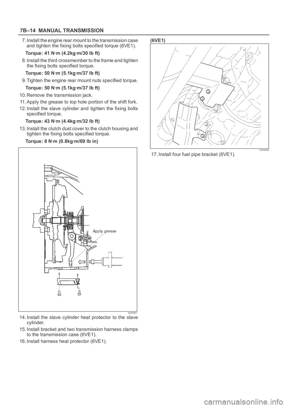
11. Apply the grease to top hole portion of the shift fork.
12. Install the slave cylinder and tighten the fixing bolts
specified torque.
Torque: 43 Nꞏm (4.4kgꞏm/32 Ib ft)
13. Install the clutch dust cover to the clutch housing and
tighten the fixing bolts specified torque.
Torque: 8 Nꞏm (0.8kgꞏm/69 Ib in)
220RS007
14. Install the slave cylinder heat protector to the slave
cylinder.
15. Install bracket and two transmission harness clamps
to the transmission case (6VE1).
16. Install harness heat protector (6VE1).(6VE1)
225RW006
17. Install four fuel pipe bracket (6VE1).