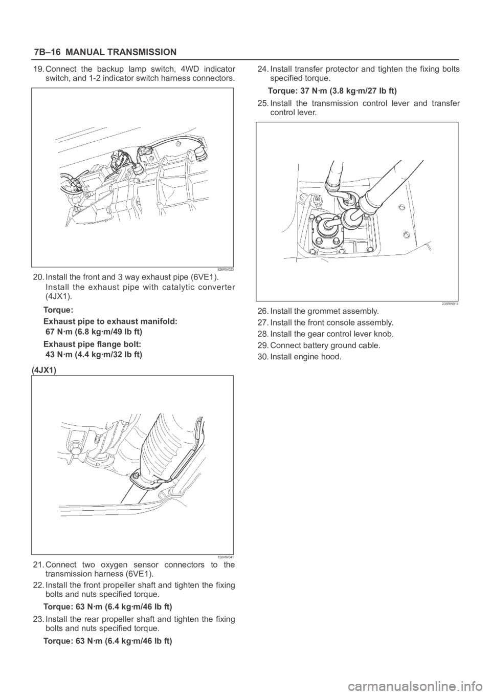
Page 2334 of 6000

7B–16MANUAL TRANSMISSION
19. Connect the backup lamp switch, 4WD indicator
switch, and 1-2 indicator switch harness connectors.
826RW023
20. Install the front and 3 way exhaust pipe (6VE1).
Install the exhaust pipe with catalytic converter
(4JX1).
Torque:
Exhaust pipe to exhaust manifold:
67 Nꞏm (6.8 kgꞏm/49 Ib ft)
Exhaust pipe flange bolt:
43 Nꞏm (4.4 kgꞏm/32 Ib ft)
(4JX1)
150RW041
21. Connect two oxygen sensor connectors to the
transmission harness (6VE1).
22. Install the front propeller shaft and tighten the fixing
bolts and nuts specified torque.
Torque: 63 Nꞏm (6.4 kgꞏm/46 Ib ft)
23. Install the rear propeller shaft and tighten the fixing
bolts and nuts specified torque.
Torque: 63 Nꞏm (6.4 kgꞏm/46 Ib ft)24. Install transfer protector and tighten the fixing bolts
specified torque.
Torque: 37 Nꞏm (3.8 kgꞏm/27 Ib ft)
25. Install the transmission control lever and transfer
control lever.
235RW014
26. Install the grommet assembly.
27. Install the front console assembly.
28. Install the gear control lever knob.
29. Connect battery ground cable.
30. Install engine hood.
Page 2370 of 6000
7B–52MANUAL TRANSMISSION
5. Using a pin punch and hammer, drive in the
slotted spring pin.
226RW058
6. Clean up the plug and plug hole.
7. Apply sealant to the plug threads. (THREE BOND
1344 or equivalent)
8. Using a torx socket wrench(T40), install and
torque the plug.
Torque: 19 Nꞏm (1.9 kgꞏm/14 lb ft)
220RW013
9. Using hexagon wrench, install and torque the
plug.
Torque: 37 Nꞏm (3.8 kgꞏm/27 lb ft)
220RW014
19. Install the reverse shift arm No.1 and reverse shift
arm No.2.
1. Mount the intermediate plate through the
aluminum plate in a vise.
226RW057
Page 2371 of 6000
MANUAL TRANSMISSION7B–53
2. Using 2 bolts, install reverse shift arm bracket.
Torque: 18 Nꞏm (1.8 kgꞏm/13 lb ft)
226RW054
3. Install reverse shift arm No.2 to the reverse shift
arm No.1. Using screwdriver and a hammer,
install the new E-ring.
226RW138
4. Install reverse shift arm No.2 to the reverse shift
arm bracket.
226RW012
20. Install the reverse shift rod.
1. Install the reverse shift arm No.1 compression
spring and ball to the reverse shift arm No.1.
226RW125
Page 2374 of 6000
7B–56MANUAL TRANSMISSION
24. Install the interlock parts.
1. Using a screwdriver and hammer, 2 new shift rod
snap rings to the 1st–2nd and 3rd–4th shift rod.
226RW051
2. Install the 3 shift detent ball and springs to the
intermediate plate.
226RW049
3. Clean up the plug hole.
4. Apply sealant to the plug threads.
sealant: THREE BOND 1344 or equivalent5. Using a torx socket wrench(T40), install and
torque the 4 plugs.
Torque: 19 Nꞏm (1.9 kgꞏm/14 lb ft)
226RW050
25. Install mainshaft assembly.
NOTE: Coat all parts with gear oil before installing them.
1. Using a plastic hammer, tap the 5th-reverse shift
rod at the reverse shift.
226RW180
Page 2377 of 6000
MANUAL TRANSMISSION7B–59
28. Install the reverse idle gear.
1. Install the reverse idle gear and reverse idle gear
shaft.
NOTE:
Insert the reverse idle gear shaft with the slot toward
rear.
Install the reverse idle gear with the reverse shift arm
No.2.
226RW019
29. Install the bearing plate.
1. Align the bearing plate to groove of the reverse
idle gear shaft.
Torque: 13 Nꞏm (1.3 kgꞏm/113 lb in)
226RW016
30. Install the 5th gear thrust washer.
1. Install the 5th gear thrust washer pin to the
counter gear shaft.
2. Install the 5th gear thrust washer to the counter
gear shaft.
NOTE: Thrust washer must be assembled with the
chamfered face of the washer toward the front.
226RW185
31. Install the counter 5th gear.
1. Install the 3 inserts and 3 compression springs to
the reverse block ring.
Reference: Push the 3 inserts with the 3 com-
pression springs to the reverse synchronizer
ring.
226RW120
Page 2380 of 6000
7B–62MANUAL TRANSMISSION
10. Install the new snap ring.
226RW026
32. Install the shift arm bolts.
1. Install and torque the 2 shift arm bolts.
Torque: 20 Nꞏm (2.0 kgꞏm/14 lb ft)
226RW023
33. Install the shift arm slotted pin.
1. Using a pin punch and a hammer, drive in the
slotted pin to the shift arm.
226RW025
34. Install the transmission case.
1. Clean up the fitting surface.
2. Apply recommended liquid gasket (THREE
BOND 1281 or equivalent), as shown.
NOTE:
Don’t dry the liquid gasket.
220RW024
Page 2381 of 6000
MANUAL TRANSMISSION7B–63
3. Stand the transmission by the wood blocks.
4. Using a plastic hammer, tap the transmission
case and attach it to the intermediate plate.
NOTE: Be careful not to add over force to bearing.
220RW022
5. Using a snap ring expander, install the front
bearing shaft snap ring (1) and counter gear shaft
bearing snap ring (2).
226RW004
6. Turn over the transmission.
35. Install the front cover.
1. Clean up the fitting surface.
2. Apply recommended liquid gasket (THREE
BOND 1281 or equivalent), as shown.NOTE:
Don’t dry the liquid gasket.
220RW025
3. Clean up and dry the bolts.
4. Apply thread sealant (THREE BOND 1344 or
equivalent) to the 8 bolts.
5. Using 8 bolts, install the front cover to the
transmission case.
Torque: 17 Nꞏm (1.7 kgꞏm/12 lb ft)
NOTE:
Tighten the all bolts evenly.
Be careful not to damage the oil seal.
220RW018
Page 2382 of 6000
7B–64MANUAL TRANSMISSION
6. Check that the top gear shaft and mainshaft
rotate.
36. Install the transfer adapter.
1. Clean up the fitting surface.
2. Apply recommended liquid gasket (THREE
BOND 1281 or equivalent), as shown.
NOTE:
Don’t dry the liquid gasket.
220RW026
3. Using a plastic hammer, tap the transfer adapter
and attach it to the intermediate plate.
220RW034
4. Using 10 bolts, install the transfer adapter.
Torque: 37 Nꞏm (3.8 kgꞏm/27 lb ft)
NOTE:
Tighten the all bolts evenly.
Don’t damage the lip of the oil seal.
Install the wire clamp (9) to the transfer adapter.
220RW083
37. Install the gear control box.
1. Align the projection of the shift lever housing to
the shaft rod groove, and install the gear control
rod.
230RW003