Page 2525 of 6000
7C–16CLUTCH
8. Apply molybdenum disulfide type grease to the areas
shown in illustration.
201RW012
9. Install the release bearing in the proper direction.
NOTE: Ensure release bearing is properly positioned
during installation, as shown in illustration.
201RW020
10. Install driven plate assembly. Use the pilot aligner
5-85253-001-0 (J-24547) to install the driven plate
assembly.
201RW027
11. Install pressure plate assembly and tighten the bolts
holding the pressure plate assembly in the order
shown in illustration.
Torque: 18 Nꞏm (1.8 kgꞏm/13 lb ft)
201RS017
12. Remove the aligner.
NOTE: Do not strike the aligner with a hammer to remove
it.
13. Install transmission assembly.
Page 2530 of 6000

CLUTCH7C–21
Torque Specifications
Master cylinder to dash panel
Torque: 16 Nꞏm (1.6 kgꞏm/12 lb ft)
Clutch pedal to dash panel
Torque: 21 Nꞏm (2.1 kgꞏm/15 lb ft)
Master cylinder push rod to yoke
Torque: 17 Nꞏm (1.7 kgꞏm/12 lb ft)
Clutch pipe to master cylinder
Torque: 20 Nꞏm (2.0 kgꞏm/14 lb ft)
Clutch pipe to flex, hose
Torque:
M 10: 16 Nꞏm (1.6 kgꞏm/12 lb ft)
M 12: 20 Nꞏm (2.0 kgꞏm/14 lb ft)
Slave cylinder to case
Torque: 43 Nꞏm (4.4 kgꞏm/32 lb ft)
Slave cylinder bleeder screw
Torque: 8 Nꞏm (0.8 kgꞏm/69 lb in)
Flexible hose to slave cylinder
Torque: 20 Nꞏm (2.0 kgꞏm/14 lb ft)
Clutch pipe to damper cylinder
Torque: 12 Nꞏm (1.2 kgꞏm/104 lb in)
Damper cylinder bleeder screw
Torque: 8 Nꞏm (0.8 kgꞏm/69 lb in)
Bleeding
1. Check the level of clutch fluid in the reservoir and
replenish if necessary.
Bleeding the damper cylinder (except V6 LHD
model).
2. Remove the rubber cap from the bleeder screw and
wipe clean the bleeder screw. Connect a vinyl tube to
the bleeder screw and insert the other end of the vinyl
tube into a transparent container.
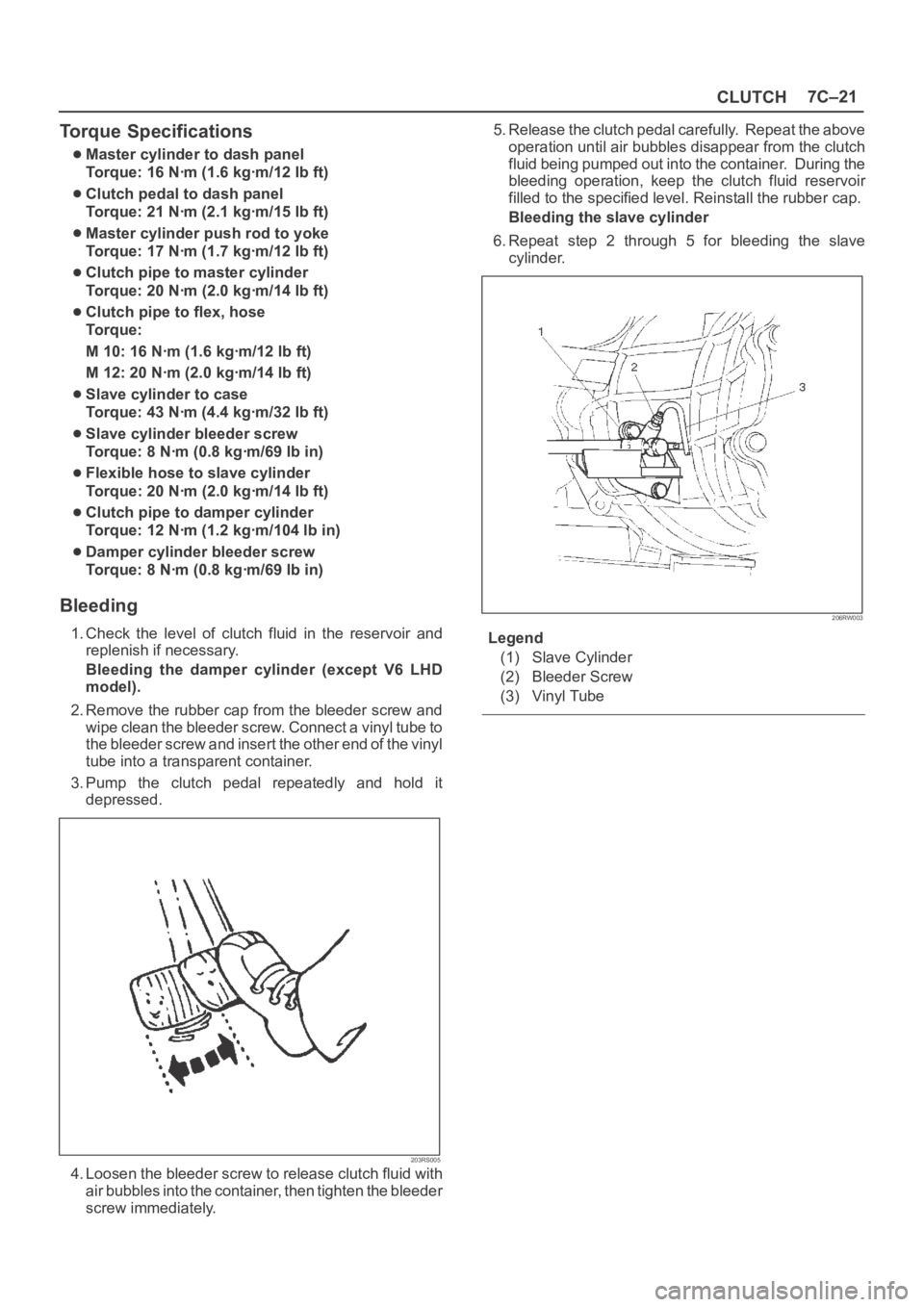
3. Pump the clutch pedal repeatedly and hold it
depressed.
203RS005
4. Loosen the bleeder screw to release clutch fluid with
air bubbles into the container, then tighten the bleeder
screw immediately.5. Release the clutch pedal carefully. Repeat the above
operation until air bubbles disappear from the clutch
fluid being pumped out into the container. During the
bleeding operation, keep the clutch fluid reservoir
filled to the specified level. Reinstall the rubber cap.
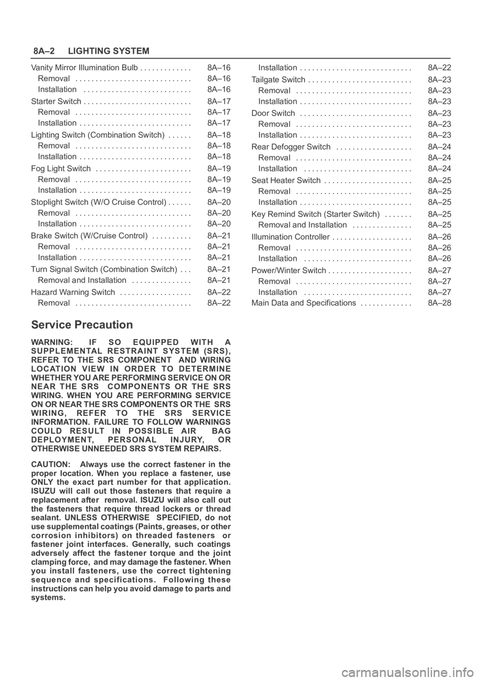
Bleeding the slave cylinder
6. Repeat step 2 through 5 for bleeding the slave
cylinder.
206RW003
Legend
(1) Slave Cylinder
(2) Bleeder Screw
(3) Vinyl Tube
Page 2532 of 6000
CLUTCH7C–23
Disassembly
(4JX1)
1. Remove damper cylinder assembly and gasket.
2. Remove push rod damper.
NOTE: The master cylinder assembly cannot be
disassembled because of point–staked rod stopper.
Inspection and Repair
Clean and inspect the removed parts.
Make necessary parts replacement if any abnormalities
such as wear, oil leaks or other damage are found through
inspection.
Reassembly
To reassemble, follow the disassembly steps in the
reverse order, noting the following points:
1.Push rod set length
RHD: 117.5 mm (4.626 in)
LHD: 119 mm (4.685 in)
2.Push rod nut torque
17 Nꞏm (1.7 kgꞏm/12 Ib ft)
3.Damper cylinder torque
47 Nꞏm (4.8 kgꞏm/35 Ib ft)
Page 2536 of 6000
CLUTCH7C–27
Main Data and Specifications
General Specifications
Ty p eDry single plate type with diaphragm spring
Size275 mm (10.83 in)
Pressure plate Outside diameter332 mm (13.07 in)
Pressure plate Clamping force7208 N (1621 lb)
Pressure plate Spring finger height49.9–51.9mm(1.965–2.043in)
Driven plate Outside diameter x inside diameter275180 mm (10.836.69 in)
Thickness Clutch disengaged8.8 mm (0.346 in)
Thickness Clutch engaged8.3 mm (0.327 in)
Total friction area 3392cm(522in)
Clutch control type Hydraulic
Clutch pedal free play 5 – 15 mm (0.20 – 0.59 in)
Clutch pedal heightLHD: 217 – 227 mm (8.543 – 8.937 in)
RHD:
(6VE1) 238.5 mm – 248.5 mm (9.390 in – 9.783 in)
(4JX1) 231 mm – 241 mm (9.094 in – 9.488 in)
Clutch pedal stroke 152.5 – 162.5 mm (6.004 – 6.398 in)
4JX1, RHD: 145 – 155mm (5.709 – 6.102 in)
Torque Specifications
E07RW053
Page 2537 of 6000
7C–28CLUTCH
Torque Specifications (Cont’d)
(6VE1 LHD)
E07RW054
Page 2538 of 6000
CLUTCH7C–29
Torque Specifications (Cont’d)
(Except 6VE1 LHD)
E07RW055
Page 2541 of 6000

8A–2LIGHTING SYSTEM
Vanity Mirror Illumination Bulb 8A–16. . . . . . . . . . . . .
Removal 8A–16. . . . . . . . . . . . . . . . . . . . . . . . . . . . .
Installation 8A–16. . . . . . . . . . . . . . . . . . . . . . . . . . .
Starter Switch 8A–17. . . . . . . . . . . . . . . . . . . . . . . . . . .
Removal 8A–17. . . . . . . . . . . . . . . . . . . . . . . . . . . . .
Installation 8A–17. . . . . . . . . . . . . . . . . . . . . . . . . . . .
Lighting Switch (Combination Switch) 8A–18. . . . . .
Removal 8A–18. . . . . . . . . . . . . . . . . . . . . . . . . . . . .
Installation 8A–18. . . . . . . . . . . . . . . . . . . . . . . . . . . .
Fog Light Switch 8A–19. . . . . . . . . . . . . . . . . . . . . . . .
Removal 8A–19. . . . . . . . . . . . . . . . . . . . . . . . . . . . .
Installation 8A–19. . . . . . . . . . . . . . . . . . . . . . . . . . . .
Stoplight Switch (W/O Cruise Control) 8A–20. . . . . .
Removal 8A–20. . . . . . . . . . . . . . . . . . . . . . . . . . . . .
Installation 8A–20. . . . . . . . . . . . . . . . . . . . . . . . . . . .
Brake Switch (W/Cruise Control) 8A–21. . . . . . . . . .
Removal 8A–21. . . . . . . . . . . . . . . . . . . . . . . . . . . . .
Installation 8A–21. . . . . . . . . . . . . . . . . . . . . . . . . . . .
Turn Signal Switch (Combination Switch) 8A–21. . .
Removal and Installation 8A–21. . . . . . . . . . . . . . .
Hazard Warning Switch 8A–22. . . . . . . . . . . . . . . . . .
Removal 8A–22. . . . . . . . . . . . . . . . . . . . . . . . . . . . . Installation 8A–22. . . . . . . . . . . . . . . . . . . . . . . . . . . .
Tailgate Switch 8A–23. . . . . . . . . . . . . . . . . . . . . . . . . .
Removal 8A–23. . . . . . . . . . . . . . . . . . . . . . . . . . . . .
Installation 8A–23. . . . . . . . . . . . . . . . . . . . . . . . . . . .
Door Switch 8A–23. . . . . . . . . . . . . . . . . . . . . . . . . . . .
Removal 8A–23. . . . . . . . . . . . . . . . . . . . . . . . . . . . .
Installation 8A–23. . . . . . . . . . . . . . . . . . . . . . . . . . . .
Rear Defogger Switch 8A–24. . . . . . . . . . . . . . . . . . .
Removal 8A–24. . . . . . . . . . . . . . . . . . . . . . . . . . . . .
Installation 8A–24. . . . . . . . . . . . . . . . . . . . . . . . . . .
Seat Heater Switch 8A–25. . . . . . . . . . . . . . . . . . . . . .
Removal 8A–25. . . . . . . . . . . . . . . . . . . . . . . . . . . . .
Installation 8A–25. . . . . . . . . . . . . . . . . . . . . . . . . . . .
Key Remind Switch (Starter Switch) 8A–25. . . . . . .
Removal and Installation 8A–25. . . . . . . . . . . . . . .
Illumination Controller 8A–26. . . . . . . . . . . . . . . . . . . .
Removal 8A–26. . . . . . . . . . . . . . . . . . . . . . . . . . . . .
Installation 8A–26. . . . . . . . . . . . . . . . . . . . . . . . . . .
Power/Winter Switch 8A–27. . . . . . . . . . . . . . . . . . . . .
Removal 8A–27. . . . . . . . . . . . . . . . . . . . . . . . . . . . .
Installation 8A–27. . . . . . . . . . . . . . . . . . . . . . . . . . .
Main Data and Specifications 8A–28. . . . . . . . . . . . .
Service Precaution
WARNING: IF SO EQUIPPED WITH A
SUPPLEMENTAL RESTRAINT SYSTEM (SRS),
REFER TO THE SRS COMPONENT AND WIRING
LOCATION VIEW IN ORDER TO DETERMINE
WHETHER YOU ARE PERFORMING SERVICE ON OR
NEAR THE SRS COMPONENTS OR THE SRS
WIRING. WHEN YOU ARE PERFORMING SERVICE
ON OR NEAR THE SRS COMPONENTS OR THE SRS
WIRING, REFER TO THE SRS SERVICE
INFORMATION. FAILURE TO FOLLOW WARNINGS
COULD RESULT IN POSSIBLE AIR BAG
DEPLOYMENT, PERSONAL INJURY, OR
OTHERWISE UNNEEDED SRS SYSTEM REPAIRS.
CAUTION: Always use the correct fastener in the
proper location. When you replace a fastener, use
ONLY the exact part number for that application.
ISUZU will call out those fasteners that require a
replacement after removal. ISUZU will also call out
the fasteners that require thread lockers or thread
sealant. UNLESS OTHERWISE SPECIFIED, do not
use supplemental coatings (Paints, greases, or other
corrosion inhibitors) on threaded fasteners or
fastener joint interfaces. Generally, such coatings
adversely affect the fastener torque and the joint
clamping force, and may damage the fastener. When
you install fasteners, use the correct tightening
sequence and specifications. Following these
instructions can help you avoid damage to parts and
systems.
Page 2557 of 6000

8A–18LIGHTING SYSTEM
Lighting Switch (Combination Switch)
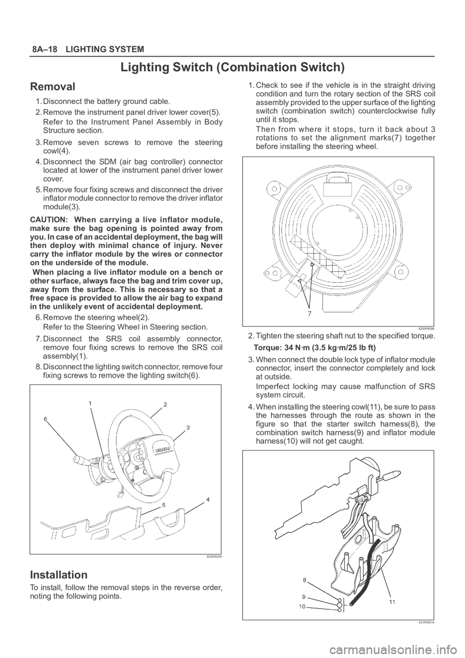
Removal
1. Disconnect the battery ground cable.
2. Remove the instrument panel driver lower cover(5).
Refer to the Instrument Panel Assembly in Body
Structure section.
3. Remove seven screws to remove the steering
cowl(4).
4. Disconnect the SDM (air bag controller) connector
located at lower of the instrument panel driver lower
cover.
5. Remove four fixing screws and disconnect the driver
inflator module connector to remove the driver inflator
module(3).
CAUTION: When carrying a live inflator module,
make sure the bag opening is pointed away from
y o u . I n c a s e o f a n a c c i d e n t a l d e p l o y m e n t , t h e b a g w i l l
then deploy with minimal chance of injury. Never
carry the inflator module by the wires or connector
on the underside of the module.
When placing a live inflator module on a bench or
other surface, always face the bag and trim cover up,
away from the surface. This is necessary so that a
free space is provided to allow the air bag to expand
in the unlikely event of accidental deployment.
6. Remove the steering wheel(2).
Refer to the Steering Wheel in Steering section.
7. Disconnect the SRS coil assembly connector,
remove four fixing screws to remove the SRS coil
assembly(1).
8. Disconnect the lighting switch connector, remove four
fixing screws to remove the lighting switch(6).
825RS039
Installation
To install, follow the removal steps in the reverse order,
noting the following points.1. Check to see if the vehicle is in the straight driving
condition and turn the rotary section of the SRS coil
assembly provided to the upper surface of the lighting
switch (combination switch) counterclockwise fully
until it stops.
Then from where it stops, turn it back about 3
rotations to set the alignment marks(7) together
before installing the steering wheel.
825RW099
2. Tighten the steering shaft nut to the specified torque.
Torque: 34 Nꞏm (3.5 kgꞏm/25 lb ft)
3. When connect the double lock type of inflator module
connector, insert the connector completely and lock
at outside.
Imperfect locking may cause malfunction of SRS
system circuit.
4. When installing the steering cowl(11), be sure to pass
the harnesses through the route as shown in the
figure so that the starter switch harness(8), the
combination switch harness(9) and inflator module
harness(10) will not get caught.
431RW014