Page 3211 of 6000
8F–16BODY STRUCTURE
5. Remove cowl cover.
Disconnect three screws.
6. Remove cowl cover seals.
7. Remove front window lower molding.8. Remove cowl cover stoppers.
Installation
To install, follow the removal steps in reverse order.
Engine Hood
Removal
1. Open the hood.
2. Support the hood.
3. Remove windowshield washer nozzle tube.
880RS001
4. Remove hood hinge bolts (3).
Before removing the hinges from the Engine hood
(1), scribe a mark (2) showing location of the hinges
to facilitate installation in the original position.
610RS003
5. Remove engine hood.
Installation
To install, follow the removal steps in the reverse order
noting the following points:
1. Tighten the engine hood fixing bolts to the specified
torque.
To r q u e : 1 3 N
m (1.3kgꞏm/113 lb in)
2. Adjust the engine hood mounting gap with reference
to Body Dimension in this section.
3. Check and see if the engine hood lock operates
normally.
Page 3212 of 6000
8F–17 BODY STRUCTURE
Air Bulge
Parts Location
610RW013
Legend
(1) Air Bulge(2) Intercooler Seal
(3) Engine Hood Insulator
Removal
1. Remove engine food insulator.
Remove the sixteen clips.
2. Remove Intercooler seal.
Remove the six clips.
3. Remove air bulge.
Remove the six nuts.
Installation
To install, follow the removal steps in the reverse order
noting the following points:1. Tighten the air bulge fixing nuts to the specified
torgue.
Torque 8 N
m (0.8kgꞏm/ 69 lb in)
Page 3213 of 6000
8F–18BODY STRUCTURE
Engine Hood Hinge
Parts Location
610RW012
Legend
(1) Hinge Fixing Bolts And Nuts
(2) Hood End Seal(3) Engine Hood Hinge
(4) Engine Hood
(5) Cowl Cover
Removal
1. Remove cowl cover.
Refer to Cowl Cover in this section.
2. Remove engine hood.
Refer to Engine Hood in this section.
3. Remove hinge fixing bolt and nut.
4. Remove engine hood hinge.
5. Remove hood end seal.
Installation
To install, follow the removal steps in reverse order noting
the following points:
1. Tighten the hood hinge fixing bolt and nut to the
specified torque.
Torque 13 N
m (1.3kgꞏm/113 lb in)
Page 3215 of 6000
8F–20BODY STRUCTURE
Installation
To install, follow the removal steps in reverse order noting
the following points:
1. Reroute the control cable to its original position, and
check and see if the lock assembly and control lever
work normally.2. Tighten the hood lock assembly fixing bolts to the
specified torque.
Torque : 10 Nm (1.0kgꞏm/87 lb in)
Radiator Grille And Front End Lower Panel
Parts Location
603RW014
Legend
(1) Front End Lower Panel(2) Head light Wiper
(3) Radiator Grille
Removal
1. Open the hood.
2. Support the hood.
3. Remove headlight wiper.
Refer to Wiper/Washer System in this section.
Page 3218 of 6000
8F–23 BODY STRUCTURE
10. Remove front fender panel.
Disconnect ten fixing bolts and two nuts.
605RW001
Installation
To install, follow the removal steps in the reverse order
noting the following points:
1. Tighten the front fender panel fixing bolts to the
specified torque.
(1) Torque : 9 N
m (0.9kgꞏm/78 lb in)
(2) Torque : 7 N
m (0.7kgꞏm/61 lb in)
Page 3221 of 6000

8F–26BODY STRUCTURE
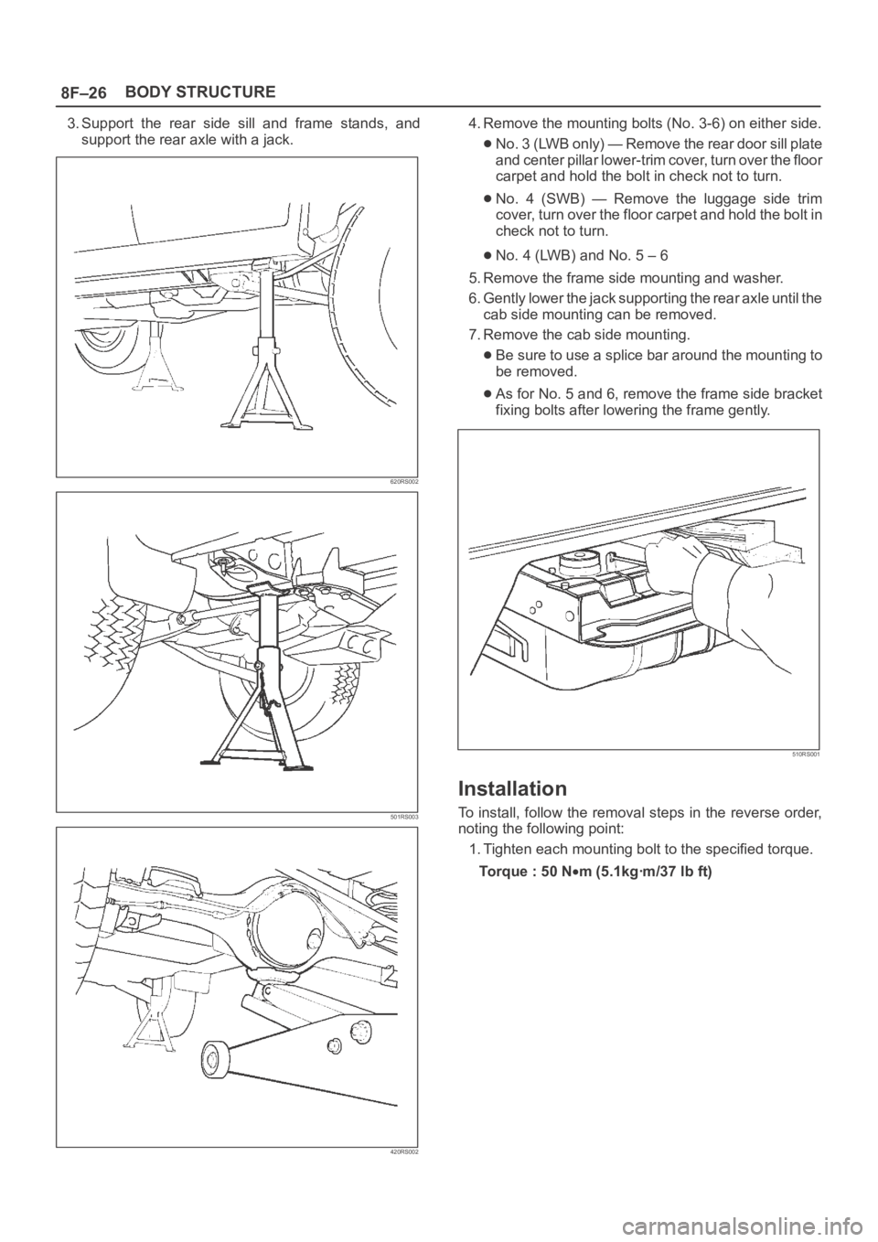
3. Support the rear side sill and frame stands, and
support the rear axle with a jack.
620RS002
501RS003
420RS002
4. Remove the mounting bolts (No. 3-6) on either side.
No. 3 (LWB only) — Remove the rear door sill plate
and center pillar lower-trim cover, turn over the floor
carpet and hold the bolt in check not to turn.
No. 4 (SWB) — Remove the luggage side trim
cover, turn over the floor carpet and hold the bolt in
check not to turn.
No. 4 (LWB) and No. 5 – 6
5. Remove the frame side mounting and washer.
6. Gently lower the jack supporting the rear axle until the
cab side mounting can be removed.
7. Remove the cab side mounting.
Be sure to use a splice bar around the mounting to
be removed.
As for No. 5 and 6, remove the frame side bracket
fixing bolts after lowering the frame gently.
510RS001
Installation
To install, follow the removal steps in the reverse order,
noting the following point:
1. Tighten each mounting bolt to the specified torque.
To r q u e : 5 0 N
m (5.1kgꞏm/37 lb ft)
Page 3251 of 6000
8F–56BODY STRUCTURE
Front Door Assembly
Parts Location
630RS001
Legend
(1) Door Check Arm Pin
(2) Front Door Assembly(3) Door Hinge Assembly
(4) Hinge Bolt
(5) Door Harness Connection
Removal
1. Disconnect the battery ground cable.
2. Remove door check arm pin (1).
630RS002
3. Remove hinge bolt.
Align the hinge bolt to the door side hinge and put a
marker on it.
4. Remove door harness connection (2).
Pull the door harness grommet out in order to
disconnect the harness connection.
810RS001
5. Remove front door assembly.
Installation
To install, follow the removal steps in the reverse order,
noting the following points:
1. Align the door fitting to the body by referring to Body
Dimensions in this section.
2. Tighten the door hinge bolts to the specified torque.
Torque : 34 N
m (3.5kgꞏm/25 lb ft)
3. Apply chassis grease to the door check arm pin and
the door hinge moving surface.
Page 3253 of 6000
8F–58BODY STRUCTURE
5. Remove door harness connection (3).
Pull the door harness grommet out in order to
disconnect the door harness connection.
810RS002
6. Remove door assembly
Installation
To install, follow the removal steps in the reverse order,
noting the following points.
1. Align the door fitting to the body by refer to Body
Dimensions in this section.
2. Tighten the door hinge bolts to the specified torque.
Torque : 34 N
m (3.5kgꞏm/25 lb ft)
3. Apply chassis grease to the check arm pin and the
door hinge moving surface.
Door Strikers
Adjustment
632RS001
1. Loosen the striker (1) screws.
2. Tap with a plastic hammer to align.
3. Tighten the striker screws.
Torque : 15 N
m (1.5kgꞏm/11 lb ft)