1998 OPEL FRONTERA air condition
[x] Cancel search: air conditionPage 2519 of 6000
7C–10CLUTCH
5. Mark the flywheel, clutch cover and pressure plate lug
for alignment when installing.
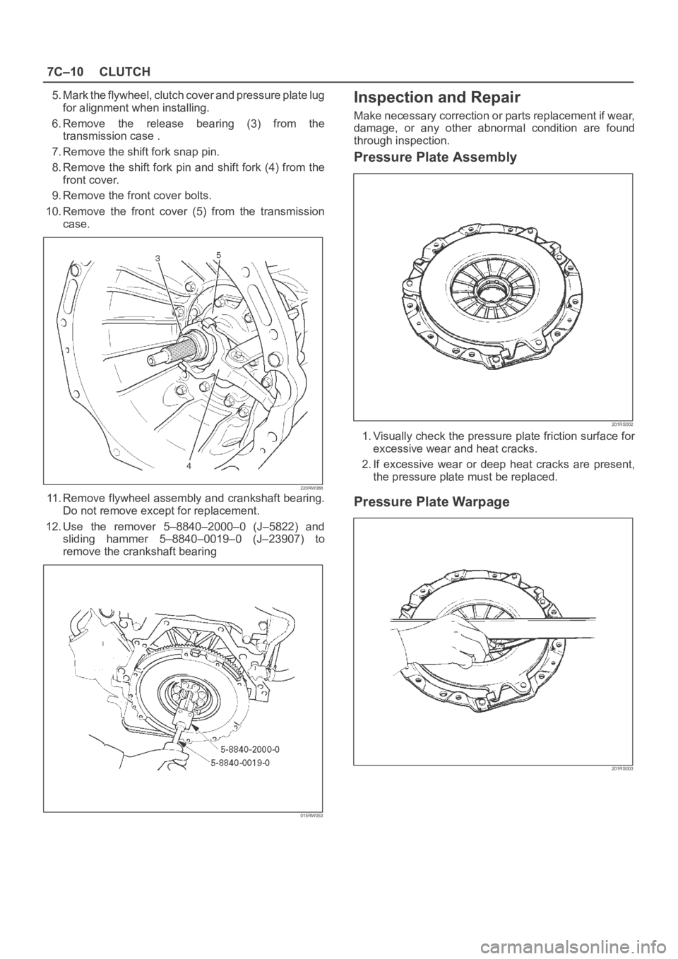
6. Remove the release bearing (3) from the
transmission case .
7. Remove the shift fork snap pin.
8. Remove the shift fork pin and shift fork (4) from the
front cover.
9. Remove the front cover bolts.
10. Remove the front cover (5) from the transmission
case.
220RW088
11. Remove flywheel assembly and crankshaft bearing.
Do not remove except for replacement.
12. Use the remover 5–8840–2000–0 (J–5822) and
sliding hammer 5–8840–0019–0 (J–23907) to
remove the crankshaft bearing
015RW053
Inspection and Repair
Make necessary correction or parts replacement if wear,
damage, or any other abnormal condition are found
through inspection.
Pressure Plate Assembly
201RS002
1. Visually check the pressure plate friction surface for
excessive wear and heat cracks.
2. If excessive wear or deep heat cracks are present,
the pressure plate must be replaced.
Pressure Plate Warpage
201RS003
Page 2557 of 6000
8A–18LIGHTING SYSTEM
Lighting Switch (Combination Switch)
Removal
1. Disconnect the battery ground cable.
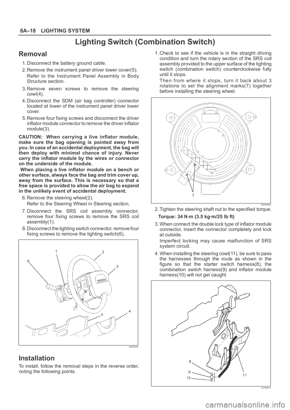
2. Remove the instrument panel driver lower cover(5).
Refer to the Instrument Panel Assembly in Body
Structure section.
3. Remove seven screws to remove the steering
cowl(4).
4. Disconnect the SDM (air bag controller) connector
located at lower of the instrument panel driver lower
cover.
5. Remove four fixing screws and disconnect the driver
inflator module connector to remove the driver inflator
module(3).
CAUTION: When carrying a live inflator module,
make sure the bag opening is pointed away from
y o u . I n c a s e o f a n a c c i d e n t a l d e p l o y m e n t , t h e b a g w i l l
then deploy with minimal chance of injury. Never
carry the inflator module by the wires or connector
on the underside of the module.
When placing a live inflator module on a bench or
other surface, always face the bag and trim cover up,
away from the surface. This is necessary so that a
free space is provided to allow the air bag to expand
in the unlikely event of accidental deployment.
6. Remove the steering wheel(2).
Refer to the Steering Wheel in Steering section.
7. Disconnect the SRS coil assembly connector,
remove four fixing screws to remove the SRS coil
assembly(1).
8. Disconnect the lighting switch connector, remove four
fixing screws to remove the lighting switch(6).
825RS039
Installation
To install, follow the removal steps in the reverse order,
noting the following points.1. Check to see if the vehicle is in the straight driving
condition and turn the rotary section of the SRS coil
assembly provided to the upper surface of the lighting
switch (combination switch) counterclockwise fully
until it stops.
Then from where it stops, turn it back about 3
rotations to set the alignment marks(7) together
before installing the steering wheel.
825RW099
2. Tighten the steering shaft nut to the specified torque.
Torque: 34 Nꞏm (3.5 kgꞏm/25 lb ft)
3. When connect the double lock type of inflator module
connector, insert the connector completely and lock
at outside.
Imperfect locking may cause malfunction of SRS
system circuit.
4. When installing the steering cowl(11), be sure to pass
the harnesses through the route as shown in the
figure so that the starter switch harness(8), the
combination switch harness(9) and inflator module
harness(10) will not get caught.
431RW014
Page 2609 of 6000
Circuit Breaker
The circuit breaker is a protective device designed to
open the circuit when a current load is in excess of rated
breaker capacity. If there is a short or other type of
overload condition in the circuit, the excessive current will
open the circuit between the circuit breaker terminals.
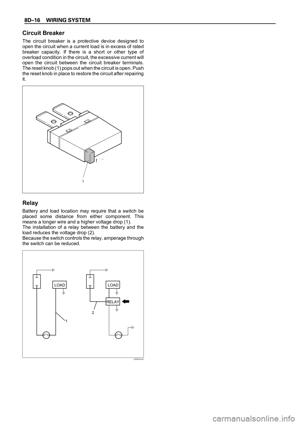
The reset knob (1) pops out when the circuit is open. Push
the reset knob in place to restore the circuit after repairing
it.
Relay
Battery and load location may require that a switch be
placed some distance from either component. This
means a longer wire and a higher voltage drop (1).
The installation of a relay between the battery and the
load reduces the voltage drop (2).
Because the switch controls the relay, amperage through
the switch can be reduced.
LOAD
12LOAD
RELAY
D08RW404
1
Page 3245 of 6000
8F–50BODY STRUCTURE
7. Remove instrument panel driver lower cover
assembly.
Remove the engine hood opener fixing screws.
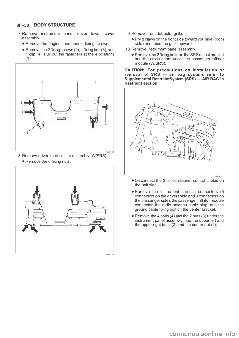
Remove the 2 fixing screws (2), 1 fixing bolt (3), and
1 clip (4). Pull out the fasteners at the 4 positions
(1).
740RW105
8. Remove driver knee bolster assembly (W/SRS).
Remove the 6 fixing nuts.
740RW122
9. Remove front defroster grille.
Pry 8 claws on the front side toward you side (room
side) and raise the grille upward.
10. Remove instrument panel assembly.
Remove the 2 fixing bolts on the SRS adjust bracket
and the cross beam under the passenger inflator
module (W/SRS).
CAUTION: For precautions on installation or
removal of SRS — air bag system, refer to
Supplemental RestraintSystem (SRS) — AIR BAG in
Restraint section.
827RW031
Disconnect the 3 air conditioner control cables on
the unit side.
Remove the instrument harness connectors (5
connectors on the drivers side and 3 connectors on
the passenger side), the passenger inflator module
connector, the radio antenna cable plug, and the
ground cable fixing bolt on the center bracket.
Remove the 4 bolts (4) and the 2 nuts (3) under the
instrument panel assembly, and the upper left and
the upper right bolts (2) and the center nut (1).
Page 3248 of 6000
8F–53 BODY STRUCTURE
Installation
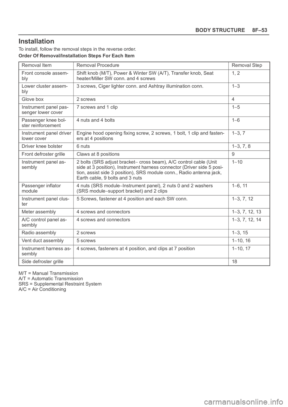
To install, follow the removal steps in the reverse order.
Order Of Removal/Installation Steps For Each Item
Removal Item
Removal ProcedureRemoval Step
Front console assem-
blyShift knob (M/T), Power & Winter SW (A/T), Transfer knob, Seat
heater/Miller SW conn. and 4 screws1, 2
Lower cluster assem-
bly3 screws, Ciger lighter conn. and Ashtray illumination conn.13
Glove box2 screws4
Instrument panel pas-
senger lower cover7 screws and 1 clip15
Passenger knee bol-
ster reinforcement4 nuts and 4 bolts16
Instrument panel driver
lower coverEngine hood opening fixing screw, 2 screws, 1 bolt, 1 clip and fasten-
ers at 4 positions13, 7
Driver knee bolster6 nuts13, 7, 8
Front defroster grilleClaws at 8 positions9
Instrument panel as-
sembly2 bolts (SRS adjust bracket cross beam), A/C control cable (Unit
side at 3 position), Instrument harness connector (Driver side 5 posi-
tion, assist side 3 position), SRS module conn., Radio antenna jack,
Earth cable, 9 bolts and 3 nuts110
Passenger inflator
module4 nuts (SRS moduleInstrument panel), 2 nuts 0 and 2 washers
(SRS module
support bracket) and 2 clips
16, 11
Instrument panel clus-
ter5 Screws, fastener at 4 position and each SW conn.13, 7, 12
Meter assembly4 screws and connectors13, 7, 12, 13
A/C control panel as-
sembly4 screws and connectors13, 7, 12, 14
Radio assembly2 screws13, 15
Vent duct assembly5 screws110, 16
Instrument harness as-
sembly4 screws, fasteners at 4 position, and clips at 7 position110, 17
Side defroster grille18
M/T = Manual Transmission
A/T = Automatic Transmission
SRS = Supplemental Restraint System
A/C = Air Conditioning
Page 3439 of 6000
SUPPLEMENTAL RESTRAINT SYSTEM 9J–2
General Description
CAUTION: When fasteners are removed, always
reinstall them at the same location from which they
were removed. If a fastener needs to be replaced, use
the correct part number fastener for that application.
If the correct part number fastener is not available, a
fastener of equal size and strength (or stronger) may
be used. Fasteners that are not reused, and those
requiring thread locking compound will be called
out. The correct torque value must be used when
installing fasteners that require it. If the above
conditions are not followed, parts or system damage
could result.
Restraint Devices
827RW006
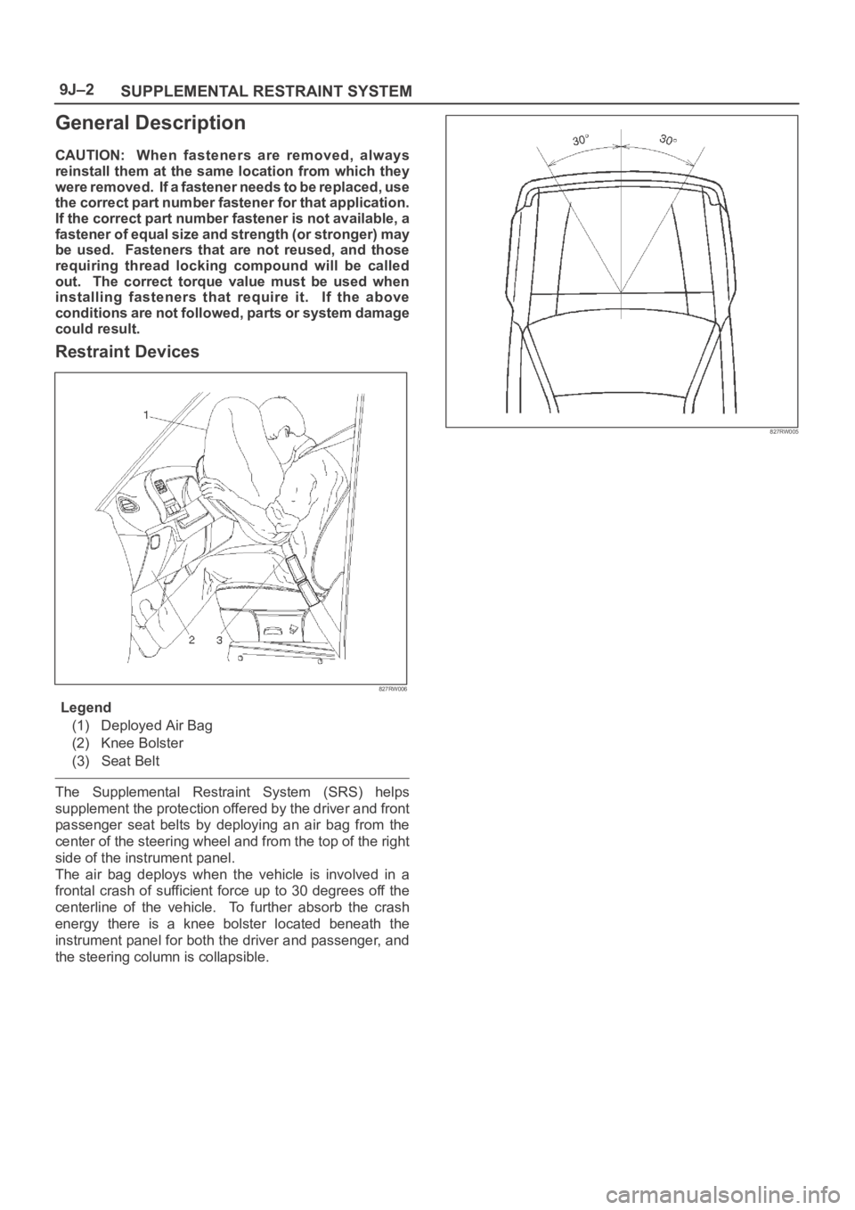
Legend
(1) Deployed Air Bag
(2) Knee Bolster
(3) Seat Belt
The Supplemental Restraint System (SRS) helps
supplement the protection offered by the driver and front
passenger seat belts by deploying an air bag from the
center of the steering wheel and from the top of the right
side of the instrument panel.
The air bag deploys when the vehicle is involved in a
frontal crash of sufficient force up to 30 degrees off the
centerline of the vehicle. To further absorb the crash
energy there is a knee bolster located beneath the
instrument panel for both the driver and passenger, and
the steering column is collapsible.
827RW005
Page 3442 of 6000
SUPPLEMENTAL RESTRAINT SYSTEM9J–5
1. Energy Reserve — The SDM maintains 24–Volt Loop
Reserve (24VLR) energy supply to provide
deployment energy when ignition voltage is lost in a
frontal crash.
2. Frontal Crash Detection — The SDM monitors
vehicle velocity changes to detect frontal crashes
which are severe enough to warrant deployment.
3. Air Bag Deployment — When a frontal crash of
sufficient force is detected, the SDM will cause
enough current to flow through the air bag assembly
to deploy the air bag.
4. Malfunction Detection — The SDM performs
diagnostic monitoring of SRS electrical components
and sets a diagnostic trouble code when a
malfunction is detected.
5. Frontal Crash Recording — The SDM records
information regarding SRS status during frontal
crash.
6. Malfunction Diagnosis — The SDM displays SRS
diagnostic trouble codes and system status
information through the use of a scan tool.
7. Driver Notification — The SDM warns the vehicle
driver of SRS malfunctions by controlling the “Air
Bag” warning lamp.
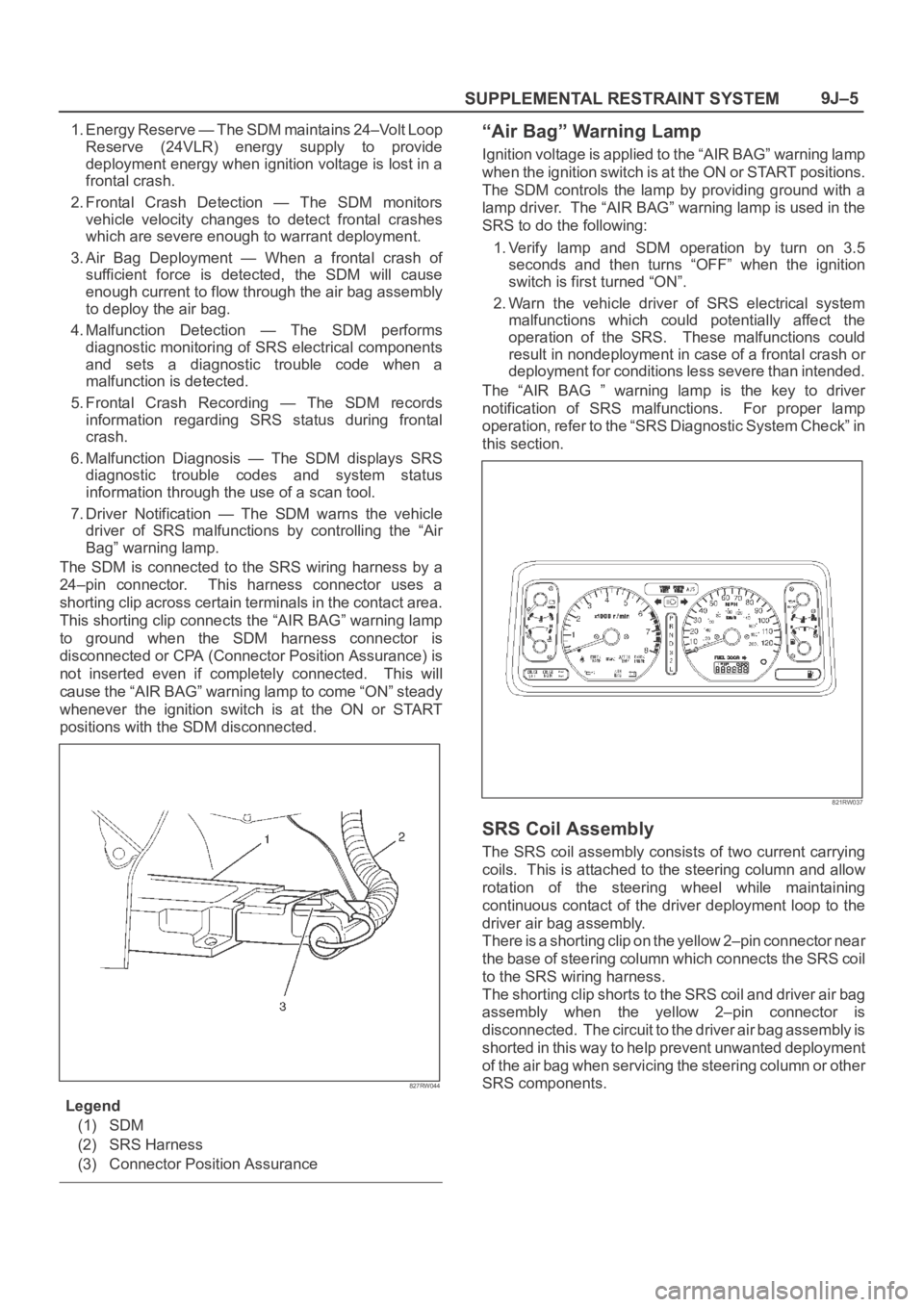
The SDM is connected to the SRS wiring harness by a
24–pin connector. This harness connector uses a
shorting clip across certain terminals in the contact area.
This shorting clip connects the “AIR BAG” warning lamp
to ground when the SDM harness connector is
disconnected or CPA (Connector Position Assurance) is
not inserted even if completely connected. This will
cause the “AIR BAG” warning lamp to come “ON” steady
whenever the ignition switch is at the ON or START
positions with the SDM disconnected.
827RW044
Legend
(1) SDM
(2) SRS Harness
(3) Connector Position Assurance
“Air Bag” Warning Lamp
Ignition voltage is applied to the “AIR BAG” warning lamp
when the ignition switch is at the ON or START positions.
The SDM controls the lamp by providing ground with a
lamp driver. The “AIR BAG” warning lamp is used in the
SRS to do the following:
1. Verify lamp and SDM operation by turn on 3.5
seconds and then turns “OFF” when the ignition
switch is first turned “ON”.
2. Warn the vehicle driver of SRS electrical system
malfunctions which could potentially affect the
operation of the SRS. These malfunctions could
result in nondeployment in case of a frontal crash or
deployment for conditions less severe than intended.
The “AIR BAG ” warning lamp is the key to driver
notification of SRS malfunctions. For proper lamp
operation, refer to the “SRS Diagnostic System Check” in
this section.
821RW037
SRS Coil Assembly
The SRS coil assembly consists of two current carrying
coils. This is attached to the steering column and allow
rotation of the steering wheel while maintaining
continuous contact of the driver deployment loop to the
driver air bag assembly.
There is a shorting clip on the yellow 2–pin connector near
the base of steering column which connects the SRS coil
to the SRS wiring harness.
The shorting clip shorts to the SRS coil and driver air bag
assembly when the yellow 2–pin connector is
disconnected. The circuit to the driver air bag assembly is
shorted in this way to help prevent unwanted deployment
of the air bag when servicing the steering column or other
SRS components.
Page 3467 of 6000
SUPPLEMENTAL RESTRAINT SYSTEM 9J–30
Service Precautions for SRS
Component Service
CAUTION: When fasteners are removed, always
reinstall them at the same location from which they
were removed. If a fastener needs to be replaced, use
the correct part number fastener for that application.
If the correct part number fastener is not available, a
fastener of equal size and strength (or stronger) may
be used. fasteners that are not reused, and those
requiring thread locking compound will be called
out. The correct torque value must be used when
installing fasteners that require it. If the above
conditions are not followed, parts or system damage
could result.
WARNING: WHEN PERFORMING SERVICE ON OR
AROUND SRS COMPONENTS OR SRS WIRING,
FOLLOW THE PROCEDURES LISTED BELOW TO
TEMPORARILY DISABLE THE SRS. FAILURE TO
FOLLOW PROCEDURES COULD RESULT IN
POSSIBLE AIR BAG DEPLOYMENT, PERSONAL
INJURY OR OTHERWISE UNNEEDED SRS REPAIRS.
The SDM in Driver–Passenger SRS can maintain
sufficient voltage to cause a deployment for up to 15
seconds after the ignition switch is turned “OFF,” the
battery is disconnected, or the fuse powering the SDM is
removed.
Many of the service procedures require removal of the
“C–21” fuse, and disconnection of the air bag assembly
from the deployment loop to avoid an accidental
deployment. If the air bag assembly is disconnected from
the deployment loop as noted in the “Disabling the SRS”
procedure that follows, service can begin immediately
without waiting for the 15 second time period to expire.
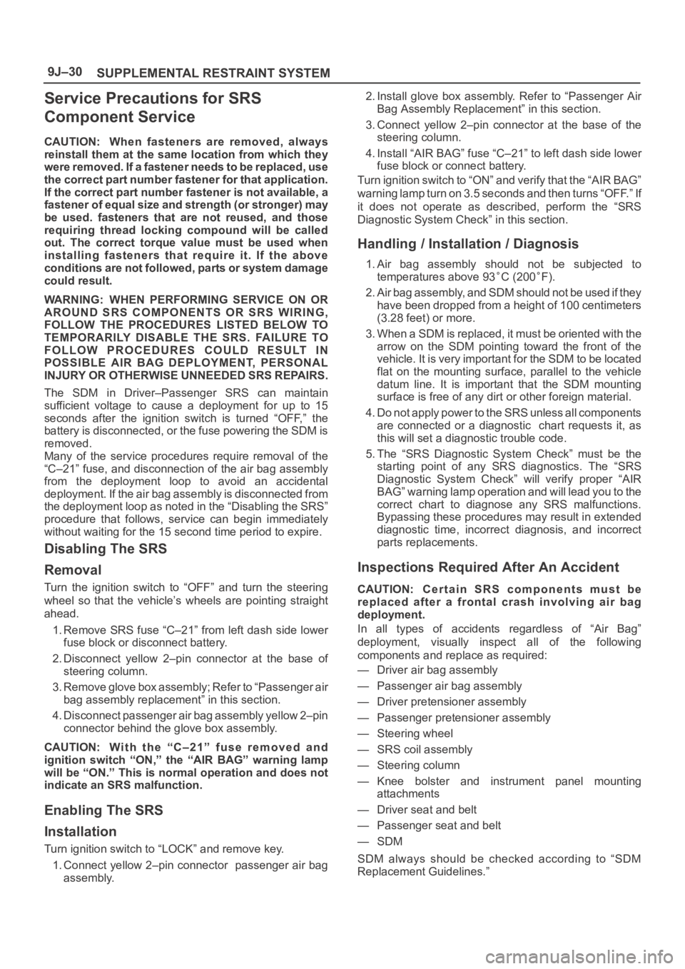
Disabling The SRS
Removal
Turn the ignition switch to “OFF” and turn the steering
wheel so that the vehicle’s wheels are pointing straight
ahead.
1. Remove SRS fuse “C–21” from left dash side lower
fuse block or disconnect battery.
2. Disconnect yellow 2–pin connector at the base of
steering column.
3 . R e m o v e g l o v e b o x a s s e m b l y ; R e f e r t o “ P a s s e n g e r a i r
bag assembly replacement” in this section.
4. Disconnect passenger air bag assembly yellow 2–pin
connector behind the glove box assembly.
CAUTION: W i t h t h e “ C – 2 1 ” f u s e r e m o v e d a n d
ignition switch “ON,” the “AIR BAG” warning lamp
will be “ON.” This is normal operation and does not
indicate an SRS malfunction.
Enabling The SRS
Installation
Turn ignition switch to “LOCK” and remove key.
1. Connect yellow 2–pin connector passenger air bag
assembly.2. Install glove box assembly. Refer to “Passenger Air
Bag Assembly Replacement” in this section.
3. Connect yellow 2–pin connector at the base of the
steering column.
4. Install “AIR BAG” fuse “C–21” to left dash side lower
fuse block or connect battery.
Turn ignition switch to “ON” and verify that the “AIR BAG”
warning lamp turn on 3.5 seconds and then turns “OFF.” If
it does not operate as described, perform the “SRS
Diagnostic System Check” in this section.
Handling / Installation / Diagnosis
1. Air bag assembly should not be subjected to
temperatures above 93
C (200F).
2. Air bag assembly, and SDM should not be used if they
have been dropped from a height of 100 centimeters
(3.28 feet) or more.
3. When a SDM is replaced, it must be oriented with the
arrow on the SDM pointing toward the front of the
vehicle. It is very important for the SDM to be located
flat on the mounting surface, parallel to the vehicle
datum line. It is important that the SDM mounting
surface is free of any dirt or other foreign material.
4. Do not apply power to the SRS unless all components
are connected or a diagnostic chart requests it, as
this will set a diagnostic trouble code.
5. The “SRS Diagnostic System Check” must be the
starting point of any SRS diagnostics. The “SRS
Diagnostic System Check” will verify proper “AIR
BAG” warning lamp operation and will lead you to the
correct chart to diagnose any SRS malfunctions.
Bypassing these procedures may result in extended
diagnostic time, incorrect diagnosis, and incorrect
parts replacements.
Inspections Required After An Accident
CAUTION: C e r t a i n S R S c o m p o n e n t s m u s t b e
replaced after a frontal crash involving air bag
deployment.
In all types of accidents regardless of “Air Bag”
deployment, visually inspect all of the following
components and replace as required:
— Driver air bag assembly
— Passenger air bag assembly
— Driver pretensioner assembly
— Passenger pretensioner assembly
— Steering wheel
— SRS coil assembly
— Steering column
— Knee bolster and instrument panel mounting
attachments
— Driver seat and belt
— Passenger seat and belt
—SDM
SDM always should be checked according to “SDM
Replacement Guidelines.”