1998 OPEL FRONTERA air condition
[x] Cancel search: air conditionPage 5708 of 6000
7A–19 AUTOMATIC TRANSMISSION (4L30–E)
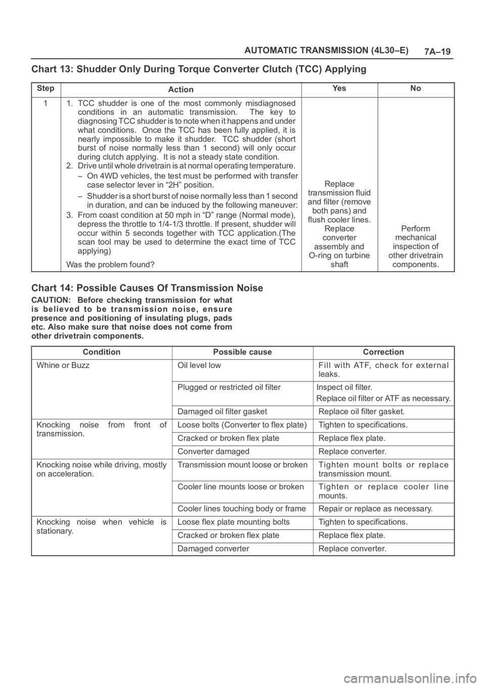
Chart 13: Shudder Only During Torque Converter Clutch (TCC) Applying
StepActionYe sNo
11. TCC shudder is one of the most commonly misdiagnosed
conditions in an automatic transmission. The key to
diagnosing TCC shudder is to note when it happens and under
what conditions. Once the TCC has been fully applied, it is
nearly impossible to make it shudder. TCC shudder (short
burst of noise normally less than 1 second) will only occur
during clutch applying. It is not a steady state condition.
2. Drive until whole drivetrain is at normal operating temperature.
– On 4WD vehicles, the test must be performed with transfer
case selector lever in “2H” position.
– Shudder is a short burst of noise normally less than 1 second
in duration, and can be induced by the following maneuver:
3. From coast condition at 50 mph in “D” range (Normal mode),
depress the throttle to 1/4-1/3 throttle. If present, shudder will
occur within 5 seconds together with TCC application.(The
scan tool may be used to determine the exact time of TCC
applying)
Was the problem found?
Replace
transmission fluid
and filter (remove
both pans) and
flush cooler lines.
Replace
converter
assembly and
O-ring on turbine
shaft
Perform
mechanical
inspection of
other drivetrain
components.
Chart 14: Possible Causes Of Transmission Noise
CAUTION: Before checking transmission for what
is believed to be transmission noise, ensure
presence and positioning of insulating plugs, pads
etc. Also make sure that noise does not come from
other drivetrain components.
Condition
Possible causeCorrection
Whine or BuzzOil level lowFill with ATF, check for external
leaks.
Plugged or restricted oil filterInspect oil filter.
Replace oil filter or ATF as necessary.
Damaged oil filter gasketReplace oil filter gasket.
Knocking noise from front of
transmission
Loose bolts (Converter to flex plate)Tighten to specifications.
transmission.Cracked or broken flex plateReplace flex plate.
Converter damagedReplace converter.
Knocking noise while driving, mostly
on acceleration.Transmission mount loose or brokenTighten mount bolts or replace
transmission mount.
Cooler line mounts loose or brokenTighten or replace cooler line
mounts.
Cooler lines touching body or frameRepair or replace as necessary.
Knocking noise when vehicle is
stationary
Loose flex plate mounting boltsTighten to specifications.
stationary.Cracked or broken flex plateReplace flex plate.
Damaged converterReplace converter.
Page 5783 of 6000

7A–2 AUTOMATIC TRANSMISSION (AW30-40LE)
VALVE BODY ASSEMBLY AND PRESSERE CONTOROL SOLENOID . . . . . . . . . . . . . . . . . . . . . . . . 7A–84
TRANSMISSION REMOVAL AND INSTALLATION. . . . . . . . . . . . . . . . . . . . . . . . . . . . . . . . . . . . . . . . . 7A–86
UNIT REPAIR . . . . . . . . . . . . . . . . . . . . . . . . . . . . . . . . . . . . . . . . . . . . . . . . . . . . . . . . . . . . . . . . . . . . . . . 7A–91
DISASSEMBLY OF MAJOR COMPONENTS . . . . . . . . . . . . . . . . . . . . . . . . . . . . . . . . . . . . . . . . . . . . . 7A–91
DISASSEMBLY, INSPECTION AND REASSEMBLY OF MINOR COMPONENTS. . . . . . . . . . . . . . . . . 7A–107
OIL PUMP . . . . . . . . . . . . . . . . . . . . . . . . . . . . . . . . . . . . . . . . . . . . . . . . . . . . . . . . . . . . . . . . . . . . . . . . 7A–108
OD PLANETARY GEAR AND OD DIRECT CLUTCH ASSEMBLY (C-0) . . . . . . . . . . . . . . . . . . . . . . . . 7A–114
OD SUPPORT ASSEMBLY . . . . . . . . . . . . . . . . . . . . . . . . . . . . . . . . . . . . . . . . . . . . . . . . . . . . . . . . . . . 7A–126
DIRECT CLUTCH ASSEMBLY (C-2) . . . . . . . . . . . . . . . . . . . . . . . . . . . . . . . . . . . . . . . . . . . . . . . . . . . . 7A–133
FORWARD CLUTCH ASSEMBLY (C-1) . . . . . . . . . . . . . . . . . . . . . . . . . . . . . . . . . . . . . . . . . . . . . . . . . 7A–141
FRONT PLANETARY GEAR . . . . . . . . . . . . . . . . . . . . . . . . . . . . . . . . . . . . . . . . . . . . . . . . . . . . . . . . . . 7A–150
PLANETARY SUN GEAR AND NO.1 ONE–WAY CLUTCH . . . . . . . . . . . . . . . . . . . . . . . . . . . . . . . . . . 7A–153
SECOND BRAKE ASSEMBLY (B–2) . . . . . . . . . . . . . . . . . . . . . . . . . . . . . . . . . . . . . . . . . . . . . . . . . . . . 7A–158
REAR PLANETARY GEAR ASSEMBLY AND OUTPUT SHAFT. . . . . . . . . . . . . . . . . . . . . . . . . . . . . . . 7A–163
FIRST AND REVERSE BRAKE (B–3) . . . . . . . . . . . . . . . . . . . . . . . . . . . . . . . . . . . . . . . . . . . . . . . . . . . 7A–171
TRANSMISSION CASE . . . . . . . . . . . . . . . . . . . . . . . . . . . . . . . . . . . . . . . . . . . . . . . . . . . . . . . . . . . . . . 7A–177
TORQUE CONVERTER . . . . . . . . . . . . . . . . . . . . . . . . . . . . . . . . . . . . . . . . . . . . . . . . . . . . . . . . . . . . . . 7A–181
REASSEMBLY OF MAJOR COMPONENTS . . . . . . . . . . . . . . . . . . . . . . . . . . . . . . . . . . . . . . . . . . . . . . 7A–182
MAIN DATA AND SPECIFICATIONS . . . . . . . . . . . . . . . . . . . . . . . . . . . . . . . . . . . . . . . . . . . . . . . . . . . . . 7A–207
GENERAL SPECIFICATIONS . . . . . . . . . . . . . . . . . . . . . . . . . . . . . . . . . . . . . . . . . . . . . . . . . . . . . . . . . 7A–207
TORQUE SPECIFICATIONS . . . . . . . . . . . . . . . . . . . . . . . . . . . . . . . . . . . . . . . . . . . . . . . . . . . . . . . . . . 7A–208
SPECIAL TOOLS . . . . . . . . . . . . . . . . . . . . . . . . . . . . . . . . . . . . . . . . . . . . . . . . . . . . . . . . . . . . . . . . . . . . 7A–211
CAUTION: When fasteners are removed, always
reinstall them at a the same location from which
they were removed. If a fastener needs to be
replaced, use the correct part number fastener for
that application. If the correct part number fastener
is not available, a fastener of equal size and
strength (or stronger) may be used. Fasteners that
are not reused, and those requiring thread locking
compound, will be called out. The correct torque
values must be used when installing fasteners that
require torque. If the above conditions are not
followed, parts or system damage could result.
Page 5798 of 6000

AUTOMATIC TRANSMISSION (AW30-40LE) 7A–17
DIAGNOSIS WITH TECH2
In this AW30-40LE transmission, troubleshooting can be
performed for electrical faults using the Tech2 scan tool.
If the CHECK TRANS lamp blinks, or if an electrical fault in the
transmission may probably exist, check trouble codes using the
Tech2 scan tool.
In the diagnostic procedures described in this manual, first
repair the faulty positions indicated by trouble code in the order
of numbers and then perform troubleshooting for the faulty
positions that are not indicated by trouble code. For correct
troubleshooting, it is necessary to first repair the trouble codes
of lower-order numbers, then to repair the trouble codes of
higher-order numbers in sequence.
How to Use This Manual:
Check trouble codes using the Tech2 scan tool.
If no codes are set:
•Refer to
F1: Data Display and identify the electrical faults
that are not indicated by trouble code.
If codes are set:
• Record all the codes displayed by the Tech2 and check if the
codes are intermittent (intermittent faults).
• Clear the codes.
• Drive the vehicle for a test to reproduce the faulty status.
• Check trouble codes again using the Tech2.
• If no code is displayed by test driving, the fault is intermittent.
In this case, refer to the cautions on intermittent conditions.
• If a code is present, refer to "DIAGNOSTIC TROUBLE
CODES (DTC) CHECK" for diagnosis.
• Because a code of high-order number may be set for the
reason that a code of low-order number has been set after
occurrence of a fault, perform repair work starting with a
lower-order number is ascending order.
Page 5801 of 6000

7A–20 AUTOMATIC TRANSMISSION (AW30-40LE)
Once the test vehicle has been identified an “Application
(Power train) Menu" screen appears. Please select the
appropriate application.
The following table shows, which functions are used for
the available equipment versions.
Diagnostic Trouble Codes
The purpose of the “Diagnostic Trouble Codes" mode is
to display stored TCM trouble codes.
When “Diagnostic Trouble Codes" is selected an
“Application Menu" screen appears.
Clear DTC Information
The purpose of the “Clear DTC Information" mode is to
command the clearing of stored TCM trouble codes.
When “Clear DTC Information" is selected, a “Clear
DTC Information", warning screen appears. This screen
informs you that by cleaning DTC's, “all stored DTC
information in controller will be erased".
Do you want to clear DTC's (Yes/No).
Press either the Yes or No key when answering.
After clearing codes, confirm system operation by test
driving the vehicle.
Allow the vehicle to shift through all four forward gears in
a manner which attempts to repeat the failure condition.
NOTE: When the trouble has not been repaired and thetrouble code cannot be erased, check the vehicle again.
DTC Information
When “DTC Information" is selected, an “Application
Menu" appears with a list of DTC information function
keys addressing DTC specifics and their origins.
Function key selections may vary for particular vehicle
and/or system.
Data Display
The purpose of the “Data Display" mode is to
continuously monitor data parameters.
The current actual values of all impor tant sensors and
signals in the system are display through F1 mode.
When “Data Display" is selected an “Application Menu"
appears.
See “TRANSMISSION DATA" and “TCC DATA” on next
page.
Snapshot
When “Snapshot" is selected an “Application Menu"
appears.
When “Transmission Snapshot" application is selected
from the “Application Menu", a “Snapshot Menu"
appears, displaying several options. “Snapshot" options
may vary from one system to another.
“Snapshot" allows a recording of all vehicle parameters.
There parameters may then be replayed at a future
point in time.
This action allows you to focus on making the condition
occur, rather than trying to view all of the data in
anticipation of the fault. The snapshot will collect
parameter information around a trigger point that you
select.
When a snapshot is taken. It is recorded onto the
PCMCIA memory card. When the Tech2 is powered
down. Snapshots are not lost.
Actuator Tests
The purpose of “Actuator Tests" mode is to check for
correct operation of electronic system actuators.
Lamps
You can operate the lamps by pressing the ON and OFF
buttons.
Preconditions: P or N position
Solenoid
Solenoid S1(1-2/3-4), S2(2-3) and TCC Solenoid
(Torque Converter Clutch)
You can operate the solenoids by pressing the ON and
OFF buttons.
Preconditions: P or N position, no vehicle speed, no
engine speed
Pressure Control Solenoid (PCS)
You can operate the PC Solenoid by pressing the ON
and OFF buttons. ON will command a maximum current
of 1000 mA and OFF a minimum of 200 mA.
Preconditions: P or N position, no vehicle speed, engine
running F0: Diagnostic Trouble Codes
F0: Read DTC Info Ordered By Priority
F1: Clear DTC Information
F2: DTC Information
F0: History
F1: MIL SVS or Message Requested
F2: Last Test Failed
F3: Test Failed Since Code Cleared
F4: Not Ran Since Code Cleared
F5: Failed This Ignition
F1: Data Display
F0: Transmission Data
F1: TCC Data
F2: Snapshot
F3: Actuator Tests
F0: Lamps
F0: Check Light Test
F1: Power Lamp Test
F2: Winter Lamp Test
F3: AT Oil Temperature Lamp Test
F1: Solenoids
F0: Solenoid 2-3 Test
F1: Solenoid 1-2/3-4 Test
F2: TCC Solenoid Test
F3: Pressure Control Solenoid (PCS)
Page 5890 of 6000
AUTOMATIC TRANSMISSION (AW30-40LE) 7A–109
241RY00006
241RY00007
241RY00008
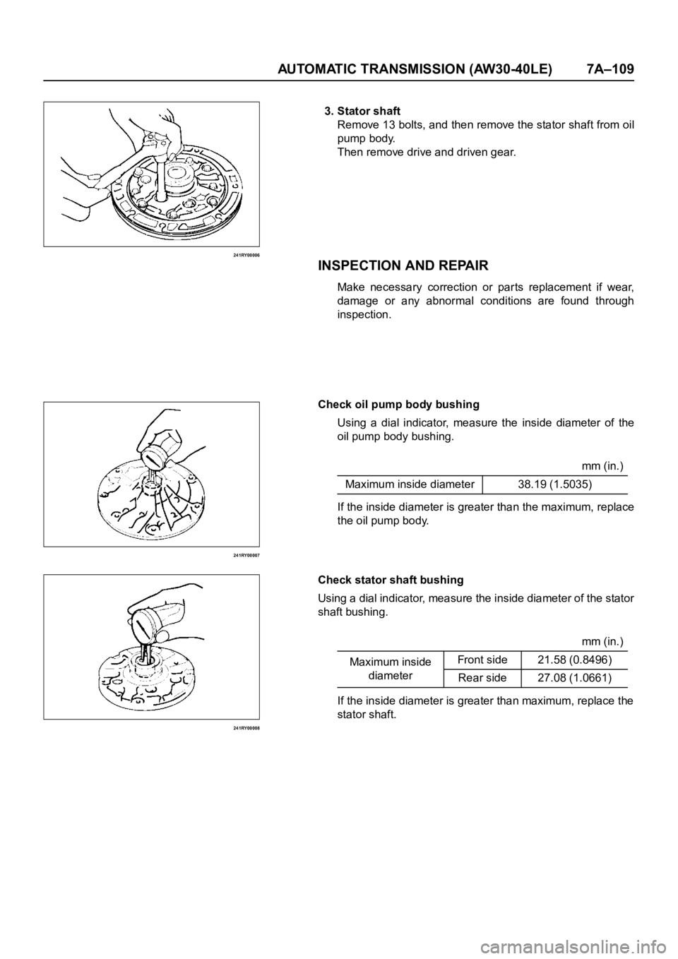
3. Stator shaft
Remove 13 bolts, and then remove the stator shaft from oil
pump body.
Then remove drive and driven gear.
INSPECTION AND REPAIR
Make necessary correction or parts replacement if wear,
damage or any abnormal conditions are found through
inspection.
Check oil pump body bushing
Using a dial indicator, measure the inside diameter of the
oil pump body bushing.
If the inside diameter is greater than the maximum, replace
the oil pump body.
Check stator shaft bushing
Using a dial indicator, measure the inside diameter of the stator
shaft bushing.
If the inside diameter is greater than maximum, replace the
stator shaft.mm (in.)
Maximum inside diameter 38.19 (1.5035)
mm (in.)
Maximum inside
diameterFront side 21.58 (0.8496)
Rear side 27.08 (1.0661)
Page 5909 of 6000
7A–128 AUTOMATIC TRANSMISSION (AW30-40LE)
252RY00046
INSPECTION AND REPAIR
Make necessary correction or parts replacement if wear,
damage or any abnormal conditions are found through
inspection.
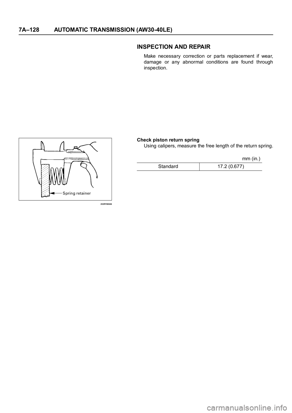
Check piston return spring
Using calipers, measure the free length of the return spring.
mm (in.)
Standard 17.2 (0.677)
Page 5981 of 6000
7A–200 AUTOMATIC TRANSMISSION (AW30-40LE)
240RY00013
240RY00014
240RY00027
Important operations
1. Second brake drum gasket
Install a new brake drum gasket to the transmission case.
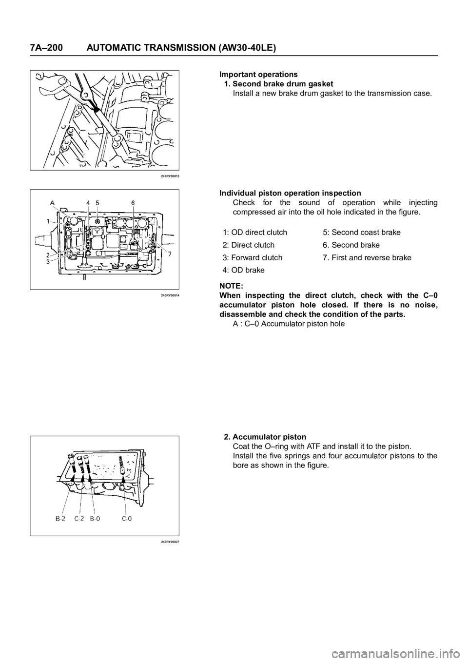
Individual piston operation inspection
Check for the sound of operation while injecting
compressed air into the oil hole indicated in the figure.
NOTE:
When inspecting the direct clutch, check with the C–0
accumulator piston hole closed. If there is no noise,
disassemble and check the condition of the parts.
A : C–0 Accumulator piston hole
2. Accumulator piston
Coat the O–ring with ATF and install it to the piston.
Install the five springs and four accumulator pistons to the
bore as shown in the figure. 1: OD direct clutch 5: Second coast brake
2: Direct clutch 6. Second brake
3: Forward clutch 7. First and reverse brake
4: OD brake
Page 5995 of 6000
7A1–2
TRANSMISSION CONTROL SYSTEM (4L30–E)
Service Precaution
WARNING: IF SO EQUIPPED WITH A
SUPPLEMENTAL RESTRAINT SYSTEM (SRS),
REFER TO THE SRS COMPONENT AND WIRING
LOCATION VIEW IN ORDER TO DETERMINE
WHETHER YOU ARE PERFORMING SERVICE ON OR
NEAR THE SRS COMPONENTS OR THE SRS
WIRING. WHEN YOU ARE PERFORMING SERVICE
ON OR NEAR THE SRS COMPONENTS OR THE SRS
WIRING, REFER TO THE SRS SERVICE
INFORMATION. FAILURE TO FOLLOW WARNINGS
COULD RESULT IN POSSIBLE AIR BAG
DEPLOYMENT, PERSONAL INJURY, OR
OTHERWISE UNNEEDED SRS SYSTEM REPAIRS.
CAUTION: Always use the correct fastener in the
proper location. When you replace a fastener, use
ONLY the exact part number for that application.
ISUZU will call out those fasteners that require a
replacement after removal. ISUZU will also call out
the fasteners that require thread lockers or thread
sealant. UNLESS OTHERWISE SPECIFIED, do not
use supplemental coatings (Paints, greases, or other
corrosion inhibitors) on threaded fasteners or
fastener joint interfaces. Generally, such coatings
adversely affect the fastener torque and the joint
clamping force, and may damage the fastener. When
you install fasteners, use the correct tightening
sequence and specifications. Following these
instructions can help you avoid damage to parts and
systems.
General Description
The 4L30–E is a 4–speed fully automatic transmission. It
uses a microcomputer as a control unit to judge running
conditions including throttle opening rate and vehicle
speed, then it sets the shifting point in the optimum timing
so that best driving performance can be achieved.
In addition, the built–in shift mode select function can
select three shift modes according to the driver’s
preference:
Normal mode –Normal shift pattern.
Winter mode –Starts in 3rd gear to reduce slippage on
ice or snow.
Power mode has a delayed upshift for when more
powerful acceleration is required.
Also, the built–in fail safe function (“backup mode”)
assures driving performance even if the vehicle speed
sensor, throttle signal or any solenoid fails.
Further, the self–diagnostic function conducts diagnosis
in a short time when the control system fails, thus
improving serviceability.
The major features of 4L30–E are as follows:
A compact structure consisting of 2 sets of planetary
gears and flat torque converter.
Electronic control selects the optimum shift mode
according to the driving conditions.
Electronic control maintains the optimum hydraulic
pressure for clutch, band brake as well as
transmission so that shift feeling is improved.
Two sets of planetary gears reduce friction of power
train.
Also, a lockup mechanism in the torque converter
reduces fuel consumption.
Wide gear ratio and high torque rate of torque
converter provide excellent starting performance.