Page 2283 of 6000
7A1–38
TRANSMISSION CONTROL SYSTEM (4L30–E)
DTC P0712 Transmission Fluid Temperature (TFT) Sensor Circuit Low Input (Cont’d)
StepNo Ye s Action
9Check circuit RED/BLK–GRN/RED for a short to ground.
Was a problem found?
Go to Step 12Go to Step 10
10Check the PCM for faulty connections.
Was a problem found?
Go to Step 12Go to Step 11
11Replace the PCM. Refer to Powertrain Control Module (PCM) in
Automatic Transmission (4L30–E) section.
Is the replacement complete?
Go to Step 12—
121. After the repair is complete, use the scan tool to select “DTC”,
then “Clear Info” function and ensure the following conditions
are met:
TFT sensor indicates a voltage greater than 0.33 volts for 2
seconds.
2. Review the scan tool “DTC info”.
Has the last test failed or is the current DTC displayed?
Begin diagnosis
again
Go to Step 1
Repair verified
Exit DTC table
Page 2286 of 6000

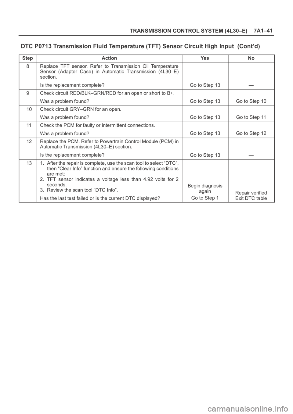
TRANSMISSION CONTROL SYSTEM (4L30–E)7A1–41
DTC P0713 Transmission Fluid Temperature (TFT) Sensor Circuit High Input (Cont’d)
StepNo Ye s Action
8Replace TFT sensor. Refer to Transmission Oil Temperature
Sensor (Adapter Case) in Automatic Transmission (4L30–E)
section.
Is the replacement complete?
Go to Step 13—
9Check circuit RED/BLK–GRN/RED for an open or short to B+.
Was a problem found?
Go to Step 13Go to Step 10
10Check circuit GRY–GRN for an open.
Was a problem found?
Go to Step 13Go to Step 11
11Check the PCM for faulty or intermittent connections.
Was a problem found?
Go to Step 13Go to Step 12
12Replace the PCM. Refer to Powertrain Control Module (PCM) in
Automatic Transmission (4L30–E) section.
Is the replacement complete?
Go to Step 13—
131. After the repair is complete, use the scan tool to select “DTC”,
then “Clear Info” function and ensure the following conditions
are met:
2. TFT sensor indicates a voltage less than 4.92 volts for 2
seconds.
3. Review the scan tool “DTC Info”.
Has the last test failed or is the current DTC displayed?
Begin diagnosis
again
Go to Step 1
Repair verified
Exit DTC table
Page 2289 of 6000
7A1–44
TRANSMISSION CONTROL SYSTEM (4L30–E)
DTC P0719 TCC Brake Switch Circuit High (Stuck On) (Cont’d)
StepNo Ye s Action
12Replace the PCM. Refer to Powertrain Control Module (PCM) in
Automatic Transmission (4L30–E) section.
Is the replacement complete?
Go to Step 13—
131. After the repair is complete, use the scan tool to select “DTC”,
then “Clear Info” function and ensure the following conditions
are met:
The PCM brake switch signal must indicate 0 volts for 1
seconds with the brake pedal applied.
2. Review the scan tool “DTC Info”.
Has the last test failed or is the current DTC displayed?
Begin diagnosis
again
Go to Step 1
Repair verified
Exit DTC table
Page 2292 of 6000
TRANSMISSION CONTROL SYSTEM (4L30–E)7A1–47
DTC P0722 Transmission Output Speed Sensor (OSS) Low Input (Cont’d)
StepNo Ye s Action
15Repair the short to B+ in circuit RED.
Is the repair complete?
Go to Step 17—
16Replace the PCM. Refer to Powertrain Control Module (PCM) in
automatic Transmission (4L30–E) section.
Is the replacement complete?
Go to Step 17—
171. After the repair is complete, use the scan tool to select “DTC”,
then “Clear Info” function and operate the vehicle under the
following conditions:
Transmission output speed is greater than 101 rpm for 3
seconds.
2. Review the scan tool “DTC Info”.
Has the last test failed or is the current DTC displayed?
Begin diagnosis
again
Go to Step 1
Repair verified
Exit DTC table
Page 2295 of 6000
7A1–50
TRANSMISSION CONTROL SYSTEM (4L30–E)
DTC P0723 Transmission Output Speed Sensor (OSS) Intermittent (Cont’d)
StepNo Ye s Action
15Repair the short to B+ in circuit RED.
Is the repair complete?
Go to Step 17—
16Replace the PCM. Refer to Powertrain Control Module (PCM) in
Automatic Transmission (4L30–E) section.
Is the replacement complete?
Go to Step 17—
171. After the repair is complete, use the scan tool to select “DTC”,
then “Clear Info” function and operate the vehicle under the
following conditions:
Transmission output speed is greater than 101 rpm for 3
seconds.
2. Review the scan tool “DTC Info”.
Has the last test failed or is the current DTC displayed?
Begin diagnosis
again
Go to Step 1
Repair verified
Exit DTC table
Page 2298 of 6000
TRANSMISSION CONTROL SYSTEM (4L30–E)7A1–53
DTC P0730 Transmission Incorrect Gear Ratio (Cont’d)
StepNo Ye s Action
5Check for possible clutch slippage.
Refer to Chart 6: Diagnostic Trouble Code (DTC) P0730 of
Mechanical/Hydraulic Diagnosis Symptoms Index in
Automatic Transmission (4L30–E) section.
Was condition found and corrected?
Go to Step 6—
61. After the repair is complete, use the scan tool to select “DTC”,
then “Clear info” function.
2. Operate the vehicle under the following conditions:
Drive the vehicle in D4 with the engine speed greater than
3,500 rpm to obtain anyone of the following gear ratios for
seven seconds.
1st 1:2.73 – 1:2.99
2nd 1:1.54 – 1:1.71
3rd 1:0.93 – 1:1.05
4th 1:0.66 – 1:0.78
Has the last test failed?
Begin diagnosis
again
Go to Step 1
Repair verified
Exit DTC table
Page 2300 of 6000

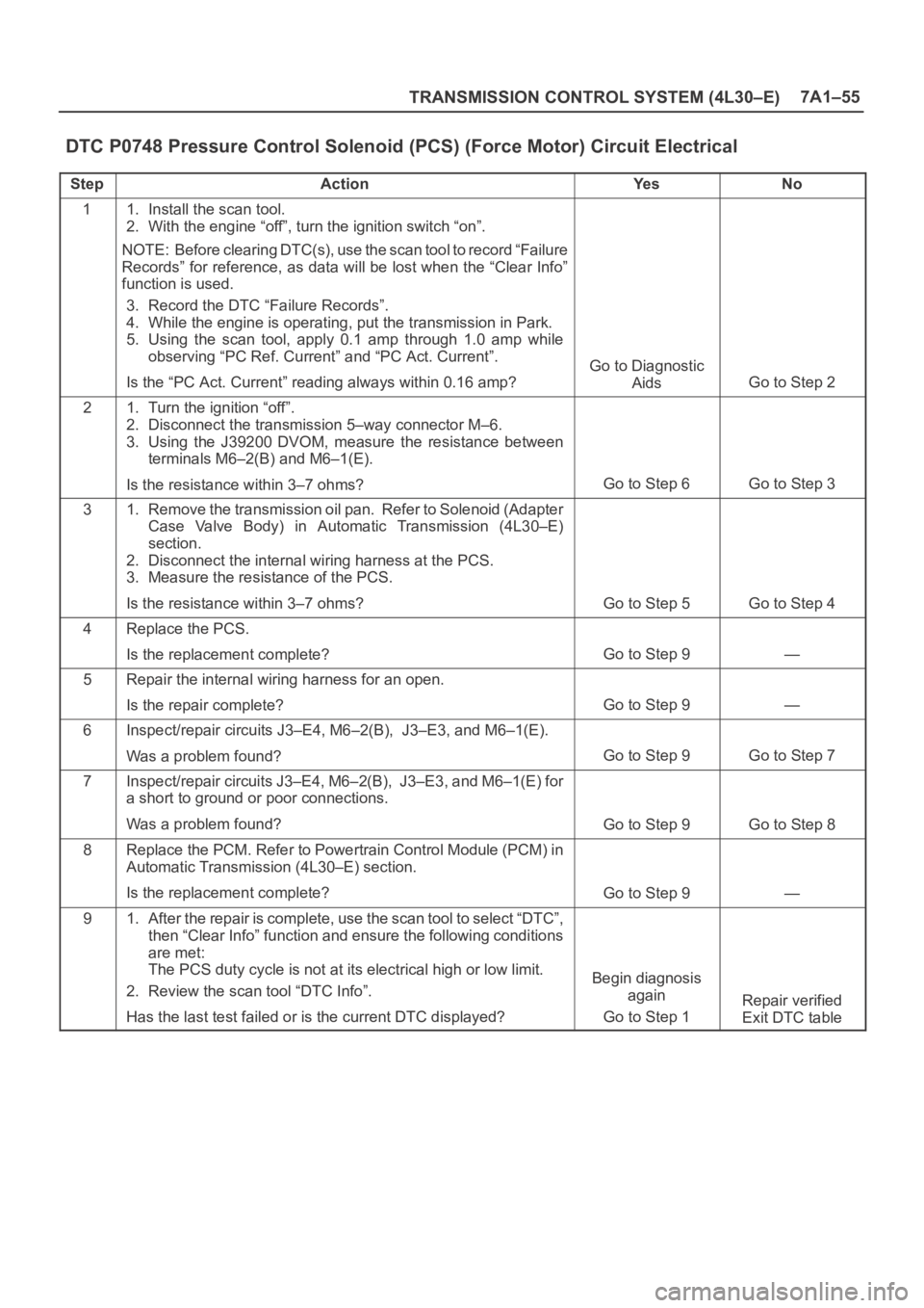
TRANSMISSION CONTROL SYSTEM (4L30–E)7A1–55
DTC P0748 Pressure Control Solenoid (PCS) (Force Motor) Circuit Electrical
StepActionYe sNo
11. Install the scan tool.
2. With the engine “off”, turn the ignition switch “on”.
NOTE: Before clearing DTC(s), use the scan tool to record “Failure
Records” for reference, as data will be lost when the “Clear Info”
function is used.
3. Record the DTC “Failure Records”.
4. While the engine is operating, put the transmission in Park.
5. Using the scan tool, apply 0.1 amp through 1.0 amp while
observing “PC Ref. Current” and “PC Act. Current”.
Is the “PC Act. Current” reading always within 0.16 amp?
Go to Diagnostic
Aids
Go to Step 2
21. Turn the ignition “off”.
2. Disconnect the transmission 5–way connector M–6.
3. Using the J39200 DVOM, measure the resistance between
terminals M6–2(B) and M6–1(E).
Is the resistance within 3–7 ohms?
Go to Step 6Go to Step 3
31. Remove the transmission oil pan. Refer to Solenoid (Adapter
Case Valve Body) in Automatic Transmission (4L30–E)
section.
2. Disconnect the internal wiring harness at the PCS.
3. Measure the resistance of the PCS.
Is the resistance within 3–7 ohms?
Go to Step 5Go to Step 4
4Replace the PCS.
Is the replacement complete?
Go to Step 9—
5Repair the internal wiring harness for an open.
Is the repair complete?
Go to Step 9—
6Inspect/repair circuits J3–E4, M6–2(B), J3–E3, and M6–1(E).
Was a problem found?
Go to Step 9Go to Step 7
7Inspect/repair circuits J3–E4, M6–2(B), J3–E3, and M6–1(E) for
a short to ground or poor connections.
Was a problem found?
Go to Step 9Go to Step 8
8Replace the PCM. Refer to Powertrain Control Module (PCM) in
Automatic Transmission (4L30–E) section.
Is the replacement complete?
Go to Step 9—
91. After the repair is complete, use the scan tool to select “DTC”,
then “Clear Info” function and ensure the following conditions
are met:
The PCS duty cycle is not at its electrical high or low limit.
2. Review the scan tool “DTC Info”.
Has the last test failed or is the current DTC displayed?
Begin diagnosis
again
Go to Step 1
Repair verified
Exit DTC table
Page 2303 of 6000

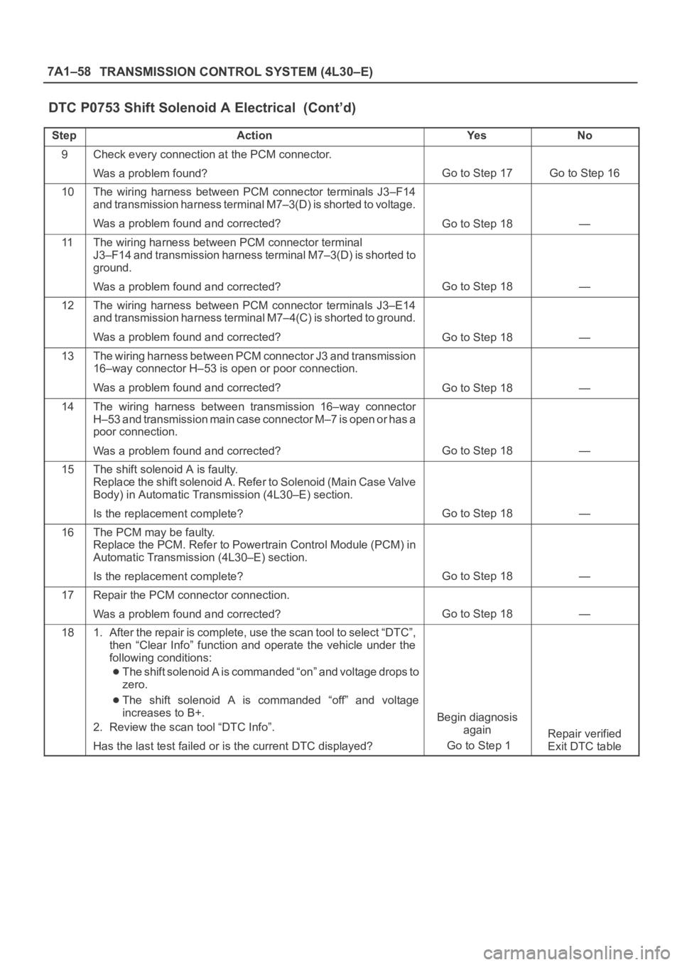
7A1–58
TRANSMISSION CONTROL SYSTEM (4L30–E)
DTC P0753 Shift Solenoid A Electrical (Cont’d)
StepNo Ye s Action
9Check every connection at the PCM connector.
Was a problem found?
Go to Step 17Go to Step 16
10The wiring harness between PCM connector terminals J3–F14
and transmission harness terminal M7–3(D) is shorted to voltage.
Was a problem found and corrected?
Go to Step 18—
11The wiring harness between PCM connector terminal
J3–F14 and transmission harness terminal M7–3(D) is shorted to
ground.
Was a problem found and corrected?
Go to Step 18—
12The wiring harness between PCM connector terminals J3–E14
and transmission harness terminal M7–4(C) is shorted to ground.
Was a problem found and corrected?
Go to Step 18—
13The wiring harness between PCM connector J3 and transmission
16–way connector H–53 is open or poor connection.
Was a problem found and corrected?
Go to Step 18—
14The wiring harness between transmission 16–way connector
H–53 and transmission main case connector M–7 is open or has a
poor connection.
Was a problem found and corrected?
Go to Step 18—
15The shift solenoid A is faulty.
Replace the shift solenoid A. Refer to Solenoid (Main Case Valve
Body) in Automatic Transmission (4L30–E) section.
Is the replacement complete?
Go to Step 18—
16The PCM may be faulty.
Replace the PCM. Refer to Powertrain Control Module (PCM) in
Automatic Transmission (4L30–E) section.
Is the replacement complete?
Go to Step 18—
17Repair the PCM connector connection.
Was a problem found and corrected?
Go to Step 18—
181. After the repair is complete, use the scan tool to select “DTC”,
then “Clear Info” function and operate the vehicle under the
following conditions:
The shift solenoid A is commanded “on” and voltage drops to
zero.
The shift solenoid A is commanded “off” and voltage
increases to B+.
2. Review the scan tool “DTC Info”.
Has the last test failed or is the current DTC displayed?
Begin diagnosis
again
Go to Step 1
Repair verified
Exit DTC table