Page 2127 of 6000

6F – 4 ENGINE EXHAUST
REMOVAL
1. Battery negative cable.
2. Raise the vehicle and support with suitable safety
stands.
3. Remove front exhaust pipe fixing nuts from engine
side.
4. Remove fixing nuts between front exhaust pipe and
center exhaust pipe, remove front exhaust pipe.
5. Disconnect center exhaust pipe and silencer,
remove center exhaust pipe.
6. Remove fixing nuts from connection part of tail pipe,
remove mounting rubber and remove silencer
bracket, silencer.
7. Remove mounting rubber for tail pipe, remove tail
pipe.
INSTALLATION
1. Install front exhaust pipe and tighten it temporarily.
2. Tighten fixing nuts of front exhaust pipe to the
specified torque. (for engine side)
Torque: 67 Nꞏm (6.8 kgꞏm/50 lb ft)
3. Tighten fixing nuts of front exhaust pipe to the
specified torque. (for center pipe side)
Torque: 43 Nꞏm (4.4 kgꞏm/32 lb ft)
4. Install silencer and tighten silencer bracket nuts to
the specified torque.
Torque: 16 Nꞏm (1.6 kgꞏm/12 lb ft)
5. Install tail pipe and tighten it.
Torque: 43 Nꞏm (4.4 kgꞏm/32 lb ft)
6. Install mounting rubbers.
Page 2128 of 6000
ENGINE EXHAUST 6F – 5
CENTER EXHAUST PIPE
REMOVAL
1. Battery negative cable.
2. Raise the vehicle and support with suitable safety
stands.
3. Remove mounting rubber.
4. Remove fixing nuts from silencer side.
5. Remove fixing nuts from front exhaust pipe.
6. Remove center exhaust pipe assembly.
INSTALLATION
1. Place center exhaust pipe in the original position
then tighten fixing nuts temporarily.
2. Install mounting rubber.
3. Tighten front exhaust pipe side nuts to the specified
torque.
Torque : 43 Nꞏm (4.4 kgꞏm/32 lb ft)
4. Tighten silencer side nuts to the specified torque.
Torque : 43 Nꞏm (4.4 kgꞏm/32 lb ft)
3
2 1
Legend
(1) Front Exhaust Pipe
(2) Center Exhaust Pipe
(3) Mounting Rubber
150RW071
Page 2129 of 6000
6F – 6 ENGINE EXHAUST
EXHAUST SILENCER
REMOVAL
1. Battery negative cable.
2. Raise the vehicle and support with suitable safety
stands.
3. Remove mounting rubber from silencer.
4. Remove silencer mounting bracket.
5. Remove fixing nuts between center exhaust pipe
and silencer.
6. Remove fixing nuts from tail pipe flange.
7. Remove silencer assembly.
INSTALLATION
1. Place silencer assembly in the original installation
position, tighten both side (front and rear) nuts
temporarily.
2. Tighten silencer mounting bracket to the specified
torque.
Torque : 16 Nꞏm (1.6 kgꞏm/12 lb ft)
3. Tighten center exhaust pipe side nuts to the
specified torque.
Torque : 43 Nꞏm (4.4 kgꞏm/32 lb ft)
4. Tighten tail pipe side nuts to the specified torque.
Torque : 43 Nꞏm (4.4 kgꞏm/32 lb ft)
5. Install silencer mounting rubber.
6
3
4
2
1
5
Legend
(1) Mounting Rubber
(2) Post Silencer
(3) Silencer(4) Mounting Bracket
(5) Mounting Rubber
(6) Tail Pipe
150RW072
Page 2130 of 6000
ENGINE EXHAUST 6F – 7
REAR EXHAUST PIPE
REMOVAL
1. Battery negative cable.
2. Raise the vehicle and support with suitable safety
stands.
3. Remove mounting rubber from post silencer.
4. Remove fixing nuts at silencer side.
5. Remove tail pipe together with post silencer.
6. Remove fixing nuts between tail pipe and post
silencer which separates them.
INSTALLATION
1. Install tail pipe and post silencer and tighten them to
the specified torque.
Torque : 43 Nꞏm (4.4 kgꞏm/32 lb ft)
2. Place tail pipe together with post silencer to original
position and tighten fixing nuts at silencer side.
Torque : 43 Nꞏm (4.4 kgꞏm/32 lb ft)
3. Install mounting rubber for post silencer.
4. Lower the vehicle.
5. Reconnect battery negative cable.
6
3
4
2
1
5
Legend
(1) Mounting Rubber
(2) Post Silencer
(3) Silencer(4) Mounting Bracket
(5) Mounting Rubber
(6) Tail Pipe
150RW072
Page 2136 of 6000
ENGINE LUBRICATION 6G – 5
OIL PUMP
REMOVAL
1. Remove battery ground cable.
2 Raise the vehicle and support with suitable safety
stand.
3. Drain engine oil.
4. Remove flywheel assembly.
5. Remove rear plate (For A/T) or flywheel housing
(For MT).
6. Remove first oil pump assembly from cylinder block
and second oil pump assembly from crank case.
INSPECTION AND REPAIR
1. Inspect flaws and/or wear on the teeth surface.
2. Inspect abnormal wear journal on the gear and in
the drive spline.
3. If problem is found during inspection, the worn parts
must be replaced.
INSTALLATION
1. Install first oil pump.
Torque: 20 Nꞏm (2.0 kgꞏm / 14.5 lb ft)
2. Install second oil pump.
Torque: 20 Nꞏm (2ꞏ0 kg.m / 14.5 lb ft)
2
1
5
6
3
4
Legend
(1) Flywheel
(2) Rear Plate
(3) First Oil Pump(4) Second Oil Pump
(5) O-ring (For 1st oil pump)
(6) O-ring (For 2nd oil pump)
012RW097
Page 2137 of 6000

6G – 6 ENGINE LUBRICATION
OIL COOLER ASSEMBLY
REMOVAL
1. Disconnect battery ground cable.
2. Drain engine coolant.
3. Remove front exhaust pipe.
4. Remove heat protector.
5. Remove exhaust valve assembly.
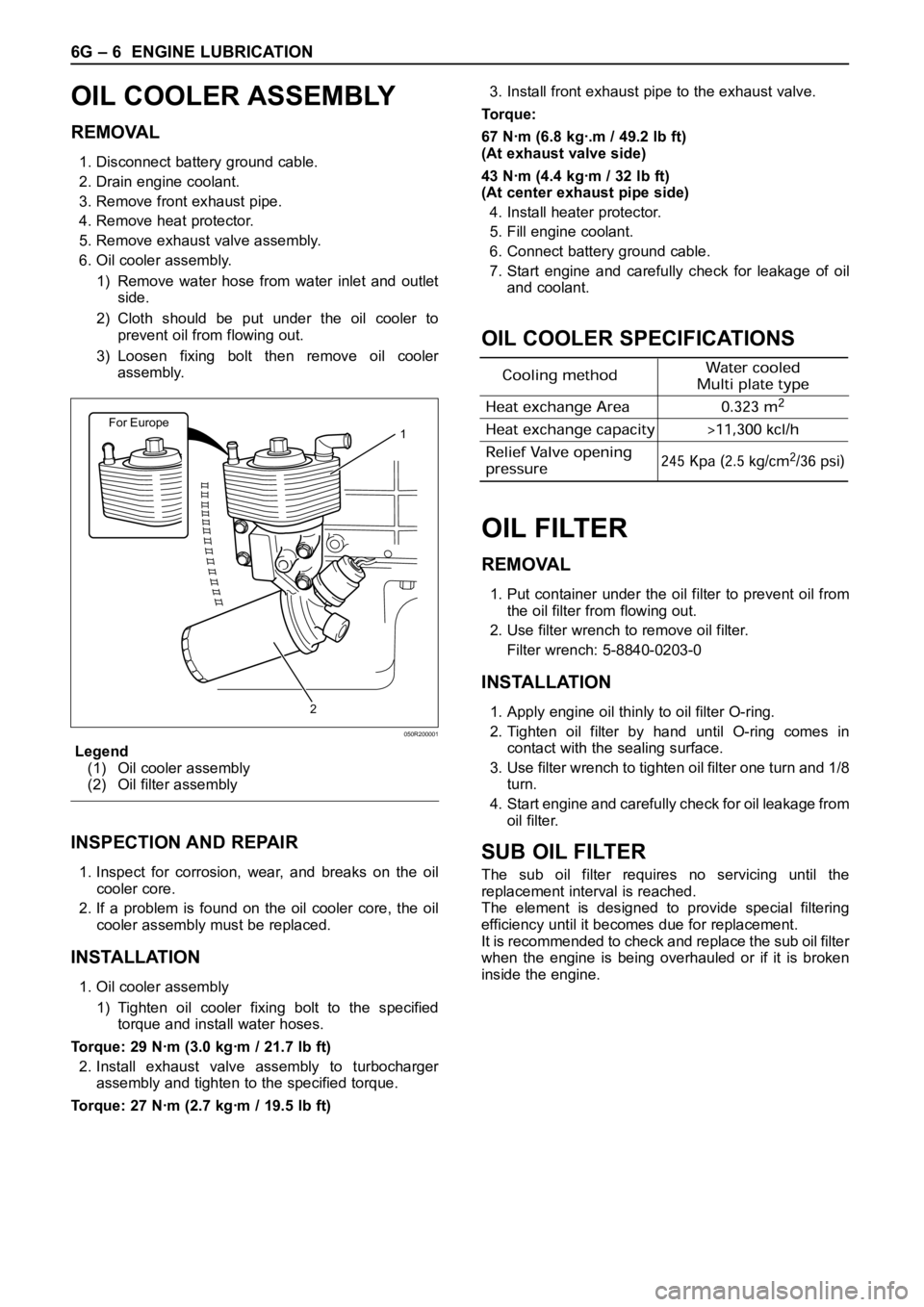
6. Oil cooler assembly.
1) Remove water hose from water inlet and outlet
side.
2) Cloth should be put under the oil cooler to
prevent oil from flowing out.
3) Loosen fixing bolt then remove oil cooler
assembly.
Legend
(1) Oil cooler assembly
(2) Oil filter assembly
INSPECTION AND REPAIR
1. Inspect for corrosion, wear, and breaks on the oil
cooler core.
2. If a problem is found on the oil cooler core, the oil
cooler assembly must be replaced.
INSTALLATION
1. Oil cooler assembly
1) Tighten oil cooler fixing bolt to the specified
torque and install water hoses.
Torque: 29 Nꞏm (3.0 kgꞏm / 21.7 lb ft)
2. Install exhaust valve assembly to turbocharger
assembly and tighten to the specified torque.
Torque: 27 Nꞏm (2.7 kgꞏm / 19.5 lb ft)3. Install front exhaust pipe to the exhaust valve.
Torque:
67 Nꞏm (6.8 kgꞏ.m / 49.2 lb ft)
(At exhaust valve side)
43 Nꞏm (4.4 kgꞏm / 32 lb ft)
(At center exhaust pipe side)
4. Install heater protector.
5. Fill engine coolant.
6. Connect battery ground cable.
7. Start engine and carefully check for leakage of oil
and coolant.
OIL COOLER SPECIFICATIONS
OIL FILTER
REMOVAL
1. Put container under the oil filter to prevent oil from
the oil filter from flowing out.
2. Use filter wrench to remove oil filter.
Filter wrench: 5-8840-0203-0
INSTALLATION
1. Apply engine oil thinly to oil filter O-ring.
2. Tighten oil filter by hand until O-ring comes in
contact with the sealing surface.
3. Use filter wrench to tighten oil filter one turn and 1/8
turn.
4. Start engine and carefully check for oil leakage from
oil filter.
SUB OIL FILTER
The sub oil filter requires no servicing until the
replacement interval is reached.
The element is designed to provide special filtering
efficiency until it becomes due for replacement.
It is recommended to check and replace the sub oil filter
when the engine is being overhauled or if it is broken
inside the engine.
For Europe1
2
050R200001
Page 2148 of 6000

INDUCTION 6J – 7
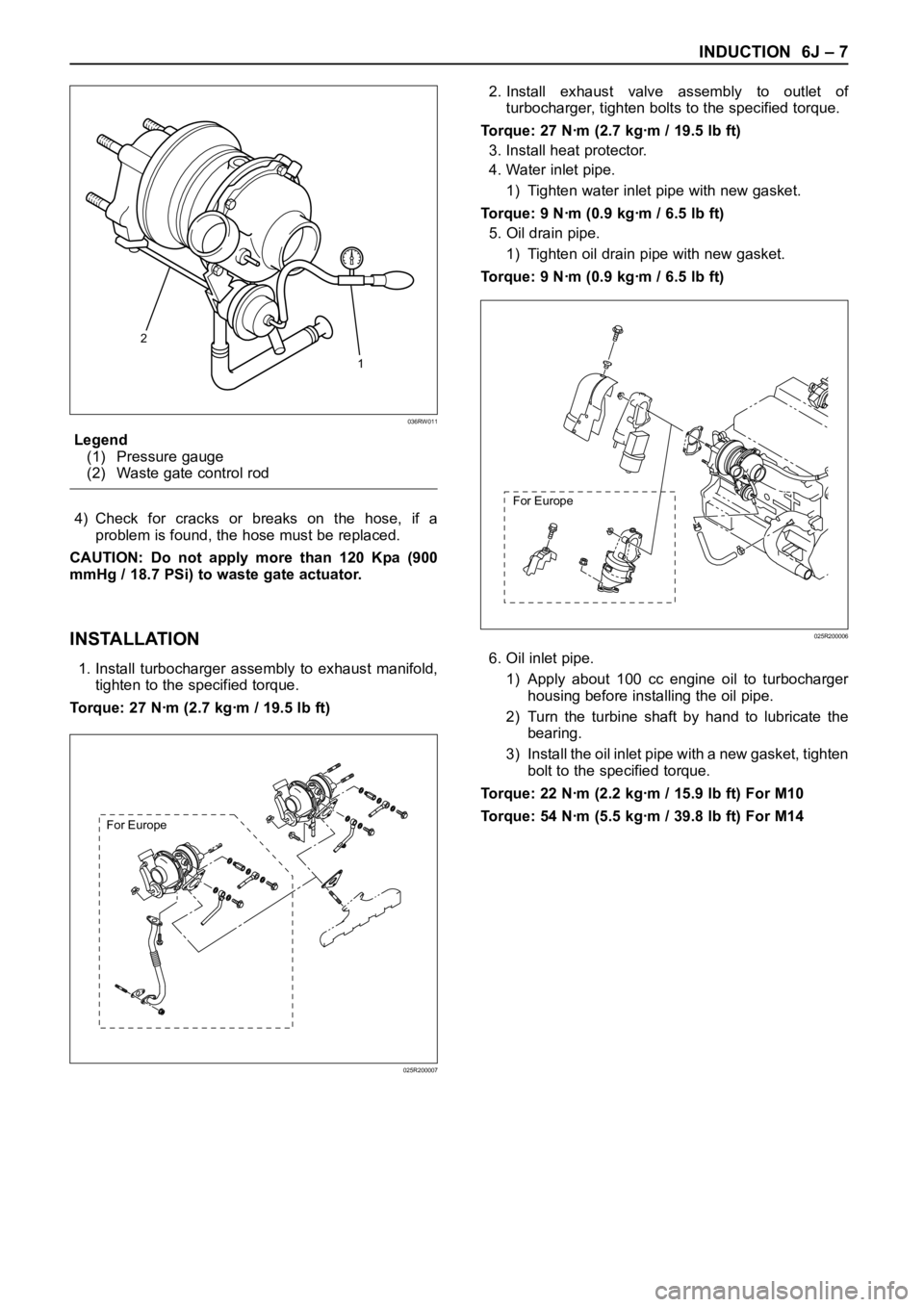
Legend
(1) Pressure gauge
(2) Waste gate control rod
4) Check for cracks or breaks on the hose, if a
problem is found, the hose must be replaced.
CAUTION: Do not apply more than 120 Kpa (900
mmHg / 18.7 PSi) to waste gate actuator.
INSTALLATION
1. Install turbocharger assembly to exhaust manifold,
tighten to the specified torque.
Torque: 27 Nꞏm (2.7 kgꞏm / 19.5 lb ft)2. Install exhaust valve assembly to outlet of
turbocharger, tighten bolts to the specified torque.
Torque: 27 Nꞏm (2.7 kgꞏm / 19.5 lb ft)
3. Install heat protector.
4. Water inlet pipe.
1) Tighten water inlet pipe with new gasket.
Torque: 9 Nꞏm (0.9 kgꞏm / 6.5 lb ft)
5. Oil drain pipe.
1) Tighten oil drain pipe with new gasket.
Torque: 9 Nꞏm (0.9 kgꞏm / 6.5 lb ft)
6. Oil inlet pipe.
1) Apply about 100 cc engine oil to turbocharger
housing before installing the oil pipe.
2) Turn the turbine shaft by hand to lubricate the
bearing.
3) Install the oil inlet pipe with a new gasket, tighten
bolt to the specified torque.
Torque: 22 Nꞏm (2.2 kgꞏm / 15.9 lb ft) For M10
Torque: 54 Nꞏm (5.5 kgꞏm / 39.8 lb ft) For M14
2
1
036RW011
For Europe
025R200007
For Europe
025R200006
Page 2149 of 6000
6J – 8 INDUCTION
7. Water inlet pipe.
1) Install water inlet pipe with a new gasket, tighten
bolts to the specified torque.
Torque: 9 Nꞏm (0.9 kgꞏm / 6.5 lb ft)
8. Install intercooler assembly.
Refer to “Intercooler” in this manual.
9. Install air cleaner cover with air duct.
10. Fill engine coolant to full level.
11. Install battery and connect battery cable.
For Europe
025R200007