Page 2072 of 6000
6E–179 4JX1–TC ENGINE DRIVEABILITY AND EMISSIONS
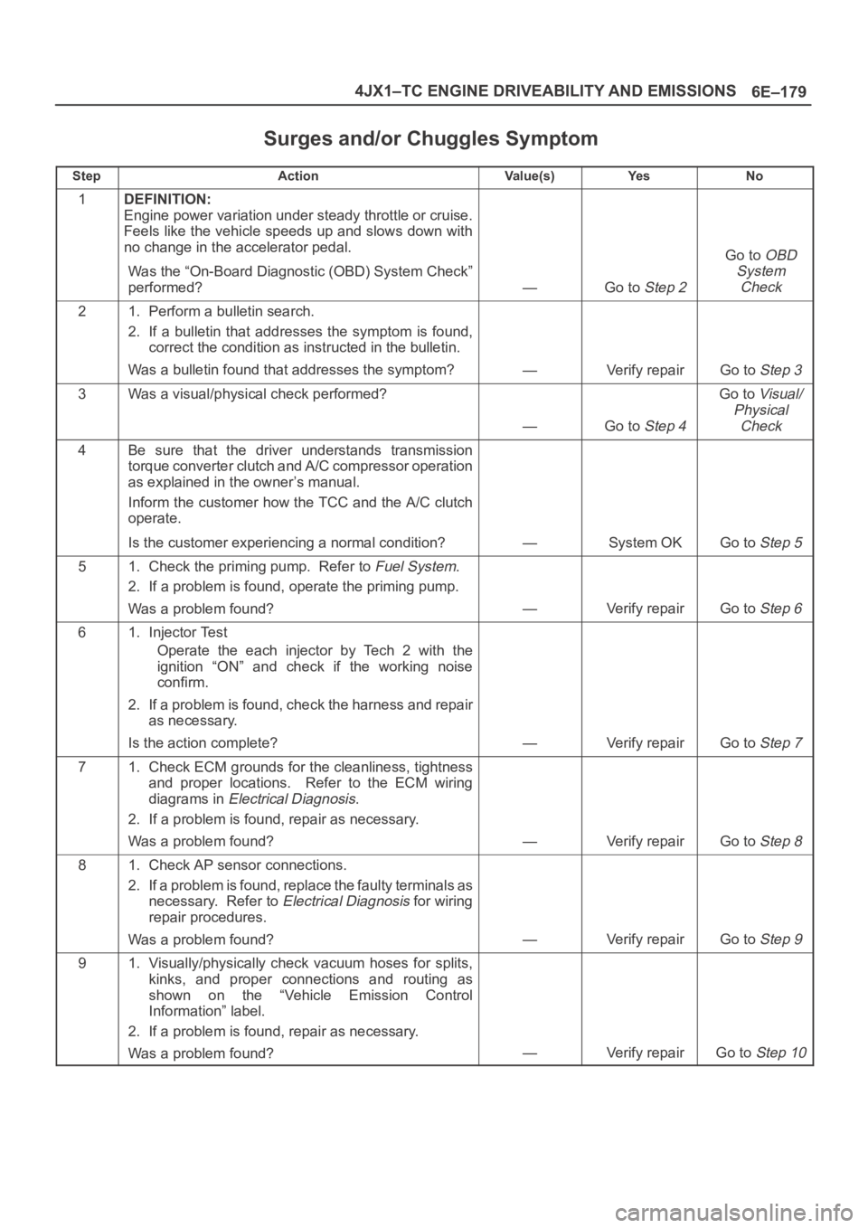
Surges and/or Chuggles Symptom
StepActionVa l u e ( s )Ye sNo
1DEFINITION:
Engine power variation under steady throttle or cruise.
Feels like the vehicle speeds up and slows down with
no change in the accelerator pedal.
Was the “On-Board Diagnostic (OBD) System Check”
performed?
—Go to Step 2
Go to OBD
System
Check
21. Perform a bulletin search.
2. If a bulletin that addresses the symptom is found,
correct the condition as instructed in the bulletin.
Was a bulletin found that addresses the symptom?
—Verify repairGo to Step 3
3Was a visual/physical check performed?
—Go to Step 4
Go to Visual/
Physical
Check
4Be sure that the driver understands transmission
torque converter clutch and A/C compressor operation
as explained in the owner’s manual.
Inform the customer how the TCC and the A/C clutch
operate.
Is the customer experiencing a normal condition?
—System OKGo to Step 5
51. Check the priming pump. Refer to Fuel System.
2. If a problem is found, operate the priming pump.
Was a problem found?
—Verify repairGo to Step 6
61. Injector Test
Operate the each injector by Tech 2 with the
ignition “ON” and check if the working noise
confirm.
2. If a problem is found, check the harness and repair
as necessary.
Is the action complete?
—Verify repairGo to Step 7
71. Check ECM grounds for the cleanliness, tightness
and proper locations. Refer to the ECM wiring
diagrams in
Electrical Diagnosis.
2. If a problem is found, repair as necessary.
Was a problem found?
—Verify repairGo to Step 8
81. Check AP sensor connections.
2. If a problem is found, replace the faulty terminals as
necessary. Refer to
Electrical Diagnosis for wiring
repair procedures.
Was a problem found?
—Verify repairGo to Step 9
91. Visually/physically check vacuum hoses for splits,
kinks, and proper connections and routing as
shown on the “Vehicle Emission Control
Information” label.
2. If a problem is found, repair as necessary.
Was a problem found?
—Verify repairGo to Step 10
Page 2074 of 6000
6E–181 4JX1–TC ENGINE DRIVEABILITY AND EMISSIONS
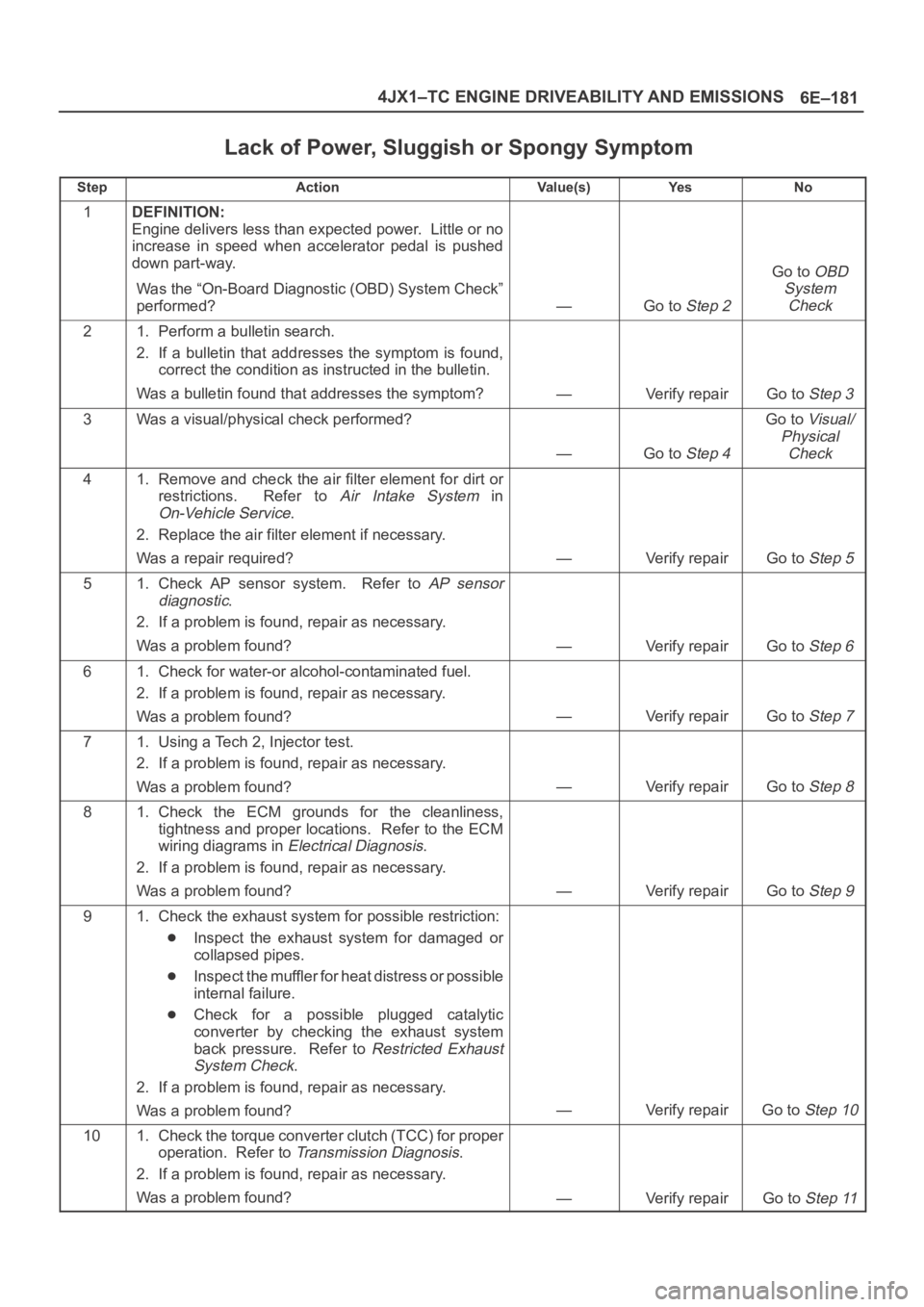
Lack of Power, Sluggish or Spongy Symptom
StepActionVa l u e ( s )Ye sNo
1DEFINITION:
Engine delivers less than expected power. Little or no
increase in speed when accelerator pedal is pushed
down part-way.
Was the “On-Board Diagnostic (OBD) System Check”
performed?
—Go to Step 2
Go to OBD
System
Check
21. Perform a bulletin search.
2. If a bulletin that addresses the symptom is found,
correct the condition as instructed in the bulletin.
Was a bulletin found that addresses the symptom?
—Verify repairGo to Step 3
3Was a visual/physical check performed?
—Go to Step 4
Go to Visual/
Physical
Check
41. Remove and check the air filter element for dirt or
restrictions. Refer to
Air Intake System in
On-Vehicle Service.
2. Replace the air filter element if necessary.
Was a repair required?
—Verify repairGo to Step 5
51. Check AP sensor system. Refer to AP sensor
diagnostic
.
2. If a problem is found, repair as necessary.
Was a problem found?
—Verify repairGo to Step 6
61. Check for water-or alcohol-contaminated fuel.
2. If a problem is found, repair as necessary.
Was a problem found?
—Verify repairGo to Step 7
71. Using a Tech 2, Injector test.
2. If a problem is found, repair as necessary.
Was a problem found?
—Verify repairGo to Step 8
81. Check the ECM grounds for the cleanliness,
tightness and proper locations. Refer to the ECM
wiring diagrams in
Electrical Diagnosis.
2. If a problem is found, repair as necessary.
Was a problem found?
—Verify repairGo to Step 9
91. Check the exhaust system for possible restriction:
Inspect the exhaust system for damaged or
collapsed pipes.
Inspect the muffler for heat distress or possible
internal failure.
Check for a possible plugged catalytic
converter by checking the exhaust system
back pressure. Refer to
Restricted Exhaust
System Check
.
2. If a problem is found, repair as necessary.
Was a problem found?
—Verify repairGo to Step 10
101. Check the torque converter clutch (TCC) for proper
operation. Refer to
Transmission Diagnosis.
2. If a problem is found, repair as necessary.
Was a problem found?
—Verify repairGo to Step 11
Page 2098 of 6000
6E–205 4JX1–TC ENGINE DRIVEABILITY AND EMISSIONS
Installation Procedure
1. Install the MAP sensor and bolts on the intake
manifold.
Torque: 4 Nꞏm (35 lb in)
035RW057
2. Connect the MAP sensor connector.
035RW053
3. Connect the EGR valve.
035RW054
4. Connect the negative battery cable.
Oil Temperature (OT) Sensor
Removal Procedure
1. Disconnect the negative battery cable.
2. Remove the battery.
035RW095
Page 2102 of 6000
6E–209 4JX1–TC ENGINE DRIVEABILITY AND EMISSIONS
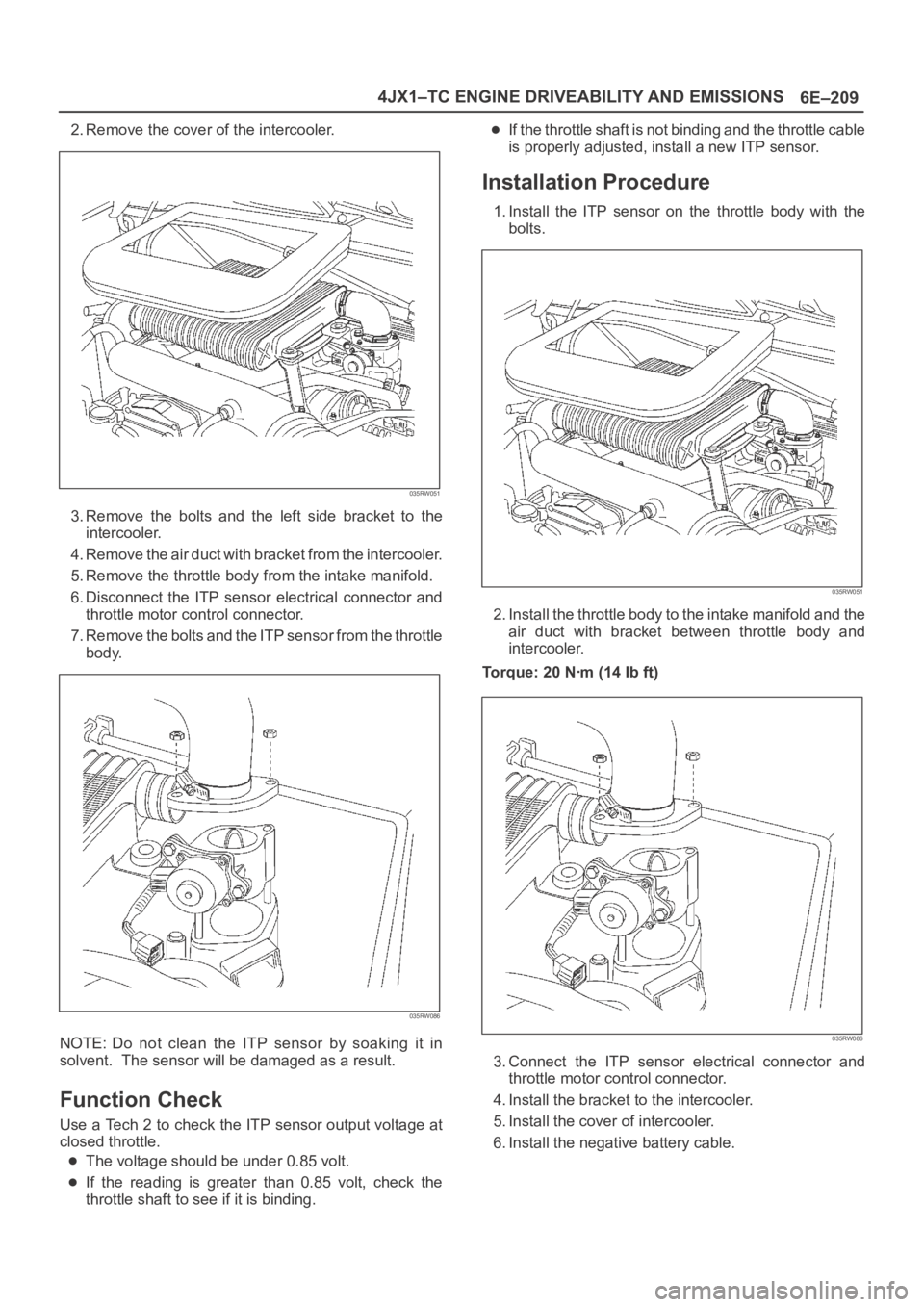
2. Remove the cover of the intercooler.
035RW051
3. Remove the bolts and the left side bracket to the
intercooler.
4 . R e m o v e t h e a i r d u c t w i t h b r a c k e t f r o m t h e i n t e r c o o l e r.
5. Remove the throttle body from the intake manifold.
6. Disconnect the ITP sensor electrical connector and
throttle motor control connector.
7. Remove the bolts and the ITP sensor from the throttle
body.
035RW086
NOTE: Do not clean the ITP sensor by soaking it in
solvent. The sensor will be damaged as a result.
Function Check
Use a Tech 2 to check the ITP sensor output voltage at
closed throttle.
The voltage should be under 0.85 volt.
If the reading is greater than 0.85 volt, check the
throttle shaft to see if it is binding.
If the throttle shaft is not binding and the throttle cable
is properly adjusted, install a new ITP sensor.
Installation Procedure
1. Install the ITP sensor on the throttle body with the
bolts.
035RW051
2. Install the throttle body to the intake manifold and the
air duct with bracket between throttle body and
intercooler.
Torque: 20 Nꞏm (14 Ib ft)
035RW086
3. Connect the ITP sensor electrical connector and
throttle motor control connector.
4. Install the bracket to the intercooler.
5. Install the cover of intercooler.
6. Install the negative battery cable.
Page 2109 of 6000
6E–216
4JX1–TC ENGINE DRIVEABILITY AND EMISSIONS
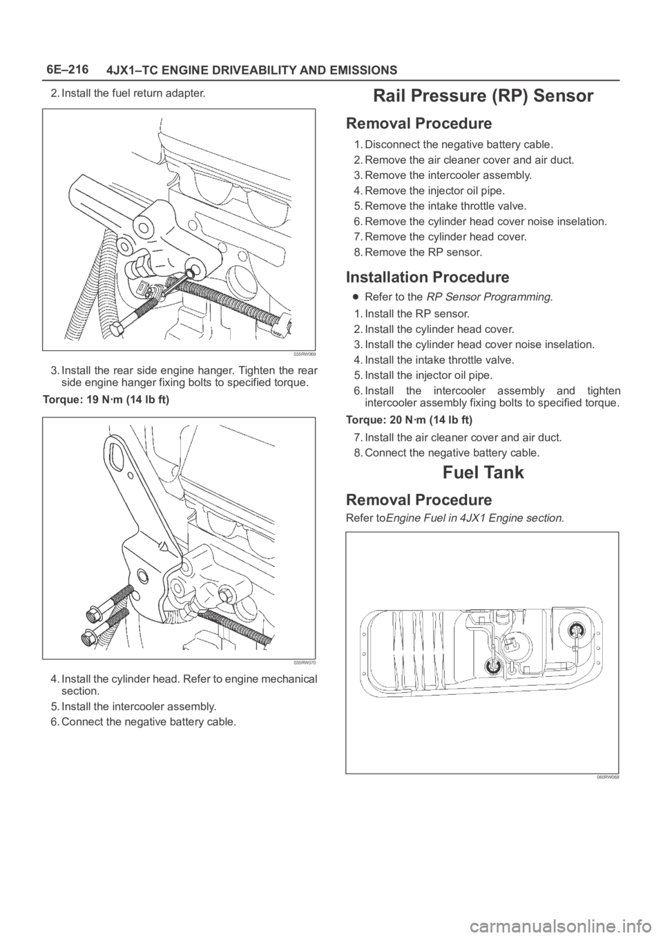
2. Install the fuel return adapter.
035RW069
3. Install the rear side engine hanger. Tighten the rear
side engine hanger fixing bolts to specified torque.
Torque: 19 Nꞏm (14 lb ft)
035RW070
4. Install the cylinder head. Refer to engine mechanical
section.
5. Install the intercooler assembly.
6. Connect the negative battery cable.
Rail Pressure (RP) Sensor
Removal Procedure
1. Disconnect the negative battery cable.
2. Remove the air cleaner cover and air duct.
3. Remove the intercooler assembly.
4. Remove the injector oil pipe.
5. Remove the intake throttle valve.
6. Remove the cylinder head cover noise inselation.
7. Remove the cylinder head cover.
8. Remove the RP sensor.
Installation Procedure
Refer to the RP Sensor Programming.
1. Install the RP sensor.
2. Install the cylinder head cover.
3. Install the cylinder head cover noise inselation.
4. Install the intake throttle valve.
5. Install the injector oil pipe.
6. Install the intercooler assembly and tighten
intercooler assembly fixing bolts to specified torque.
Torque: 20 Nꞏm (14 lb ft)
7. Install the air cleaner cover and air duct.
8. Connect the negative battery cable.
Fuel Tank
Removal Procedure
Refer toEngine Fuel in 4JX1 Engine section.
060RW068
Page 2110 of 6000
6E–217 4JX1–TC ENGINE DRIVEABILITY AND EMISSIONS
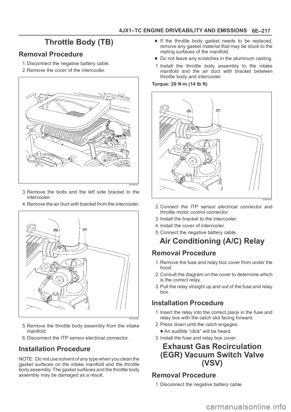
Throttle Body (TB)
Removal Procedure
1. Disconnect the negative battery cable.
2. Remove the cover of the intercooler.
035RW051
3. Remove the bolts and the left side bracket to the
intercooler.
4 . R e m o v e t h e a i r d u c t w i t h b r a c k e t f r o m t h e i n t e r c o o l e r.
035RW086
5. Remove the throttle body assembly from the intake
manifold.
6. Disconnect the ITP sensor electrical connector.
Installation Procedure
NOTE: Do not use solvent of any type when you clean the
gasket surfaces on the intake manifold and the throttle
body assembly. The gasket surfaces and the throttle body
assembly may be damaged as a result.
If the throttle body gasket needs to be replaced,
remove any gasket material that may be stuck to the
mating surfaces of the manifold.
Do not leave any scratches in the aluminum casting.
1. Install the throttle body assembly to the intake
manifold and the air duct with bracket between
throttle body and intercooler.
Torque: 20 Nꞏm (14 Ib ft)
035RW086
2. Connect the ITP sensor electrical connector and
throttle motor control connector.
3. Install the bracket to the intercooler.
4. Install the cover of intercooler.
5. Connect the negative battery cable.
Air Conditioning (A/C) Relay
Removal Procedure
1. Remove the fuse and relay box cover from under the
hood.
2. Consult the diagram on the cover to determine which
is the correct relay.
3. Pull the relay straight up and out of the fuse and relay
box.
Installation Procedure
1. Insert the relay into the correct place in the fuse and
relay box with the catch slot facing forward.
2. Press down until the catch engages.
An audible “click” will be heard.
3. Install the fuse and relay box cover.
Exhaust Gas Recirculation
(EGR) Vacuum Switch Valve
(VSV)
Removal Procedure
1. Disconnect the negative battery cable.
Page 2111 of 6000
6E–218
4JX1–TC ENGINE DRIVEABILITY AND EMISSIONS
2. Disconnect the EGR VSV connector and vacuum
hose from the EGR VSV.
035RW063
3. Remove the MAP sensor assembly and EGR VSV.
035RW067
4. Remove the EGR VSV from the MAP sensor bracket.
035RW062
Installation Procedure
1. Install the EGR VSV and tighten nut to specified
torque.
Torque: 8 Nꞏm (69 lb in)
035RW062
Page 2112 of 6000
6E–219 4JX1–TC ENGINE DRIVEABILITY AND EMISSIONS
2. Install the MAP sensor assembly and EGR VSV and
tighten MAP sensor bracket fixing bolts specified
torque.
Torque: 9 Nꞏm (78 lb in)
035RW067
3. Connect the EGR VSV connector and vacuum hose
in the EGR VSV.
035RW063
4. Connect the negative battery cable.
Electronic Vacuum Regurating
Va l v e ( E V RV )
Removal Procedure
1. Disconnect the negative battery cable.
2. Disconnect the EVRV hose and the EVRV connector.
035RW065
3. Remove the EVRV.
035RW064