Page 1863 of 6000
6C – 18 ENGINE FUEL
4. Remove lock bolt of idle gear A.
5. Install timing gear case cover.
Refer to “Timing gear” in this manual.
6. Install front plate.
Torque: 20 Nꞏm (2.0 kgꞏm/14.5 lb ft)
7. Install timing pulley of high pressure oil pump.
Torque: 10 Nꞏm (1.0 kgꞏm/7.2 lb ft)
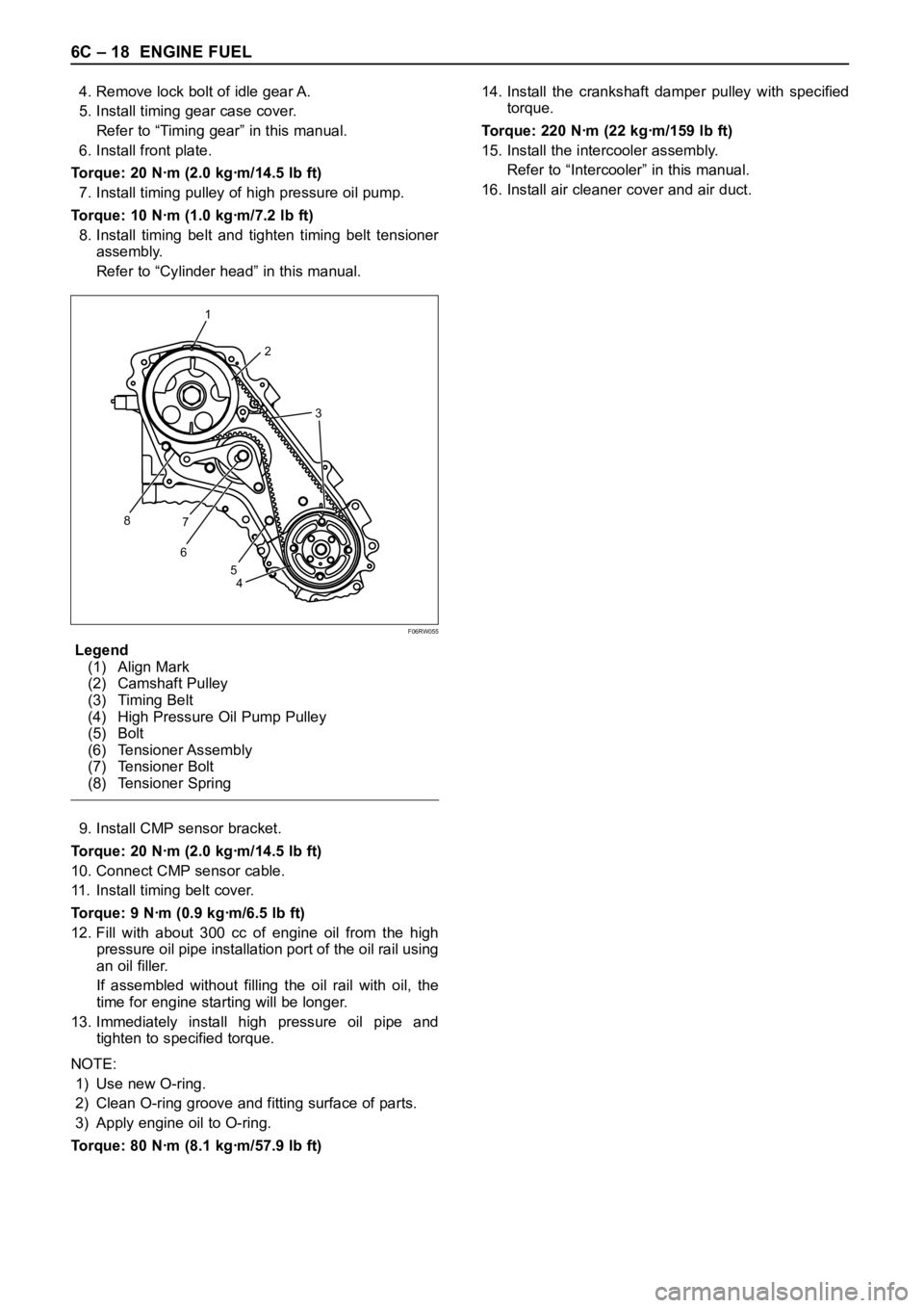
8. Install timing belt and tighten timing belt tensioner
assembly.
Refer to “Cylinder head” in this manual.
Legend
(1) Align Mark
(2) Camshaft Pulley
(3) Timing Belt
(4) High Pressure Oil Pump Pulley
(5) Bolt
(6) Tensioner Assembly
(7) Tensioner Bolt
(8) Tensioner Spring
9. Install CMP sensor bracket.
Torque: 20 Nꞏm (2.0 kgꞏm/14.5 lb ft)
10. Connect CMP sensor cable.
11. Install timing belt cover.
Torque: 9 Nꞏm (0.9 kgꞏm/6.5 lb ft)
12. Fill with about 300 cc of engine oil from the high
pressure oil pipe installation port of the oil rail using
an oil filler.
If assembled without filling the oil rail with oil, the
time for engine starting will be longer.
13. Immediately install high pressure oil pipe and
tighten to specified torque.
NOTE:
1) Use new O-ring.
2) Clean O-ring groove and fitting surface of parts.
3) Apply engine oil to O-ring.
Torque: 80 Nꞏm (8.1 kgꞏm/57.9 lb ft)14. Install the crankshaft damper pulley with specified
torque.
Torque: 220 Nꞏm (22 kgꞏm/159 lb ft)
15. Install the intercooler assembly.
Refer to “Intercooler” in this manual.
16. Install air cleaner cover and air duct.
1
2
3
8
67
4 5
F06RW055
Page 1864 of 6000
ENGINE FUEL 6C – 19
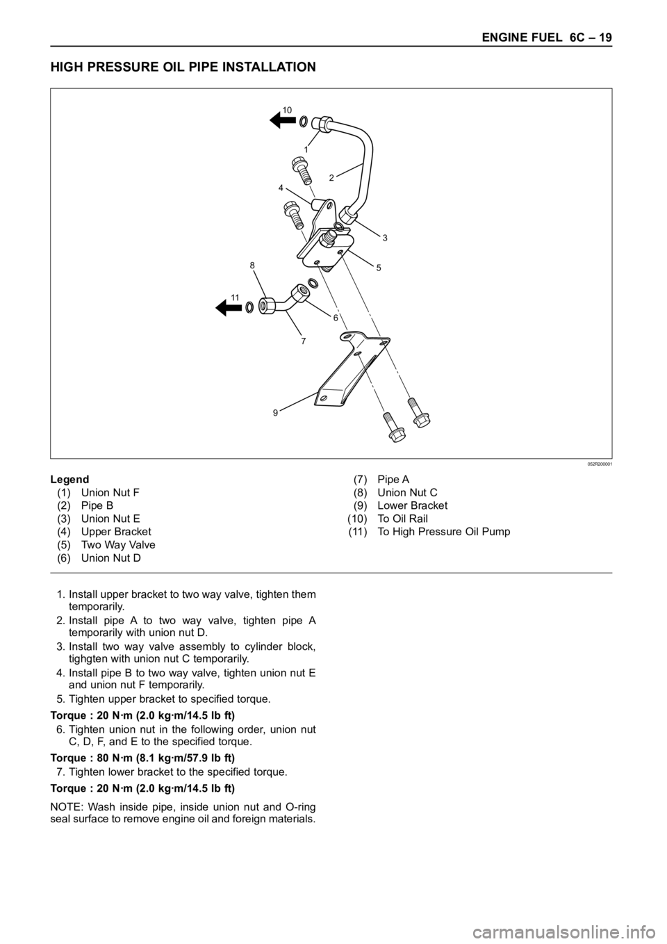
HIGH PRESSURE OIL PIPE INSTALLATION
1. Install upper bracket to two way valve, tighten them
temporarily.
2. Install pipe A to two way valve, tighten pipe A
temporarily with union nut D.
3. Install two way valve assembly to cylinder block,
tighgten with union nut C temporarily.
4. Install pipe B to two way valve, tighten union nut E
and union nut F temporarily.
5. Tighten upper bracket to specified torque.
Torque : 20 Nꞏm (2.0 kgꞏm/14.5 lb ft)
6. Tighten union nut in the following order, union nut
C, D, F, and E to the specified torque.
Torque : 80 Nꞏm (8.1 kgꞏm/57.9 lb ft)
7. Tighten lower bracket to the specified torque.
Torque : 20 Nꞏm (2.0 kgꞏm/14.5 lb ft)
NOTE: Wash inside pipe, inside union nut and O-ring
seal surface to remove engine oil and foreign materials.
6
5
7
9
8
114
1
2
3 10
Legend
(1) Union Nut F
(2) Pipe B
(3) Union Nut E
(4) Upper Bracket
(5) Two Way Valve
(6) Union Nut D(7) Pipe A
(8) Union Nut C
(9) Lower Bracket
(10) To Oil Rail
(11) To High Pressure Oil Pump
052R200001
Page 1865 of 6000
6C – 20 ENGINE FUEL
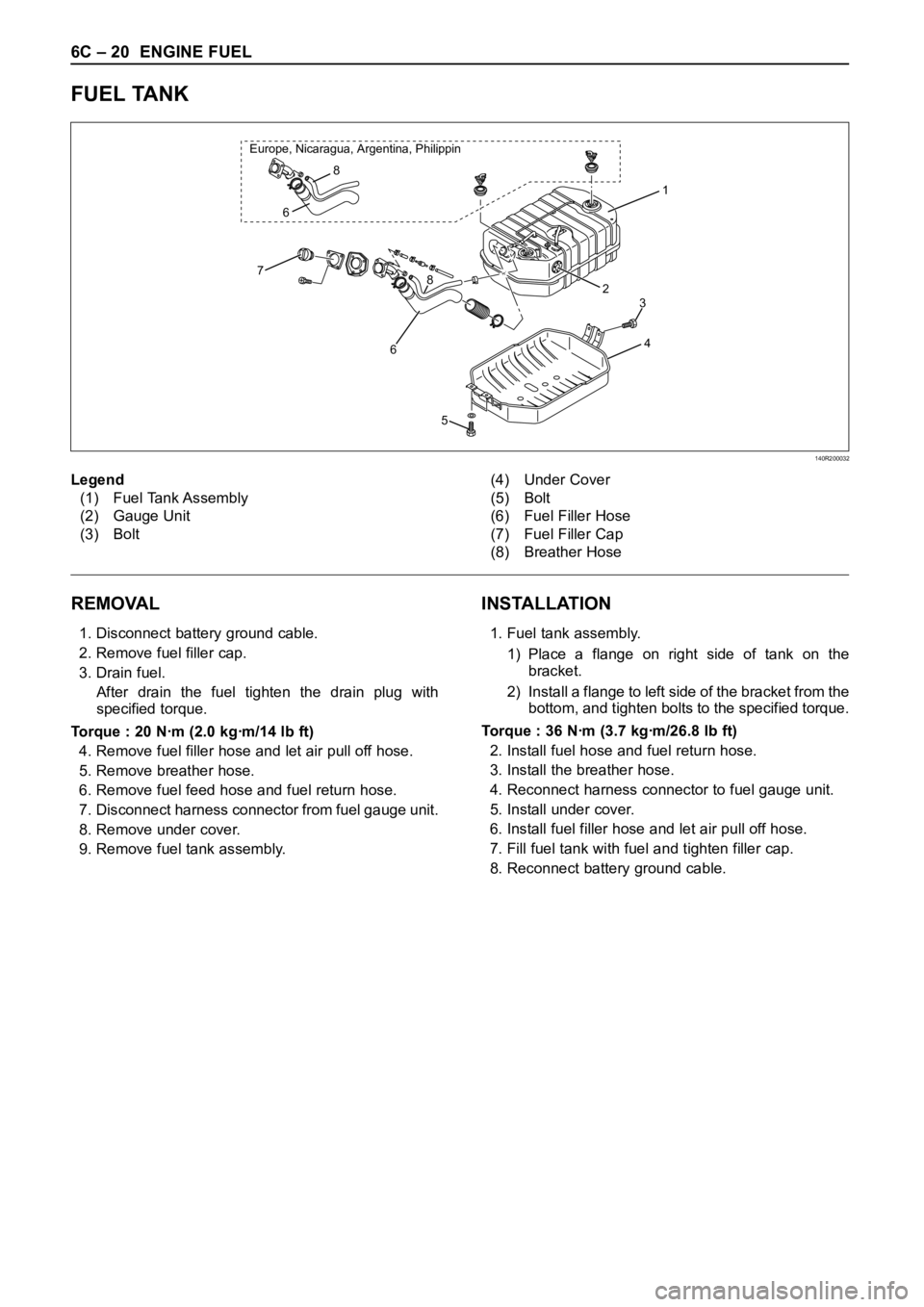
FUEL TANK
REMOVAL
1. Disconnect battery ground cable.
2. Remove fuel filler cap.
3. Drain fuel.
After drain the fuel tighten the drain plug with
specified torque.
Torque : 20 Nꞏm (2.0 kgꞏm/14 lb ft)
4. Remove fuel filler hose and let air pull off hose.
5. Remove breather hose.
6. Remove fuel feed hose and fuel return hose.
7. Disconnect harness connector from fuel gauge unit.
8. Remove under cover.
9. Remove fuel tank assembly.
INSTALLATION
1. Fuel tank assembly.
1) Place a flange on right side of tank on the
bracket.
2) Install a flange to left side of the bracket from the
bottom, and tighten bolts to the specified torque.
Torque : 36 Nꞏm (3.7 kgꞏm/26.8 lb ft)
2. Install fuel hose and fuel return hose.
3. Install the breather hose.
4. Reconnect harness connector to fuel gauge unit.
5. Install under cover.
6. Install fuel filler hose and let air pull off hose.
7. Fill fuel tank with fuel and tighten filler cap.
8. Reconnect battery ground cable.
1
2
4
8
678 Europe, Nicaragua, Argentina, Philippin
6
5
3
Legend
(1) Fuel Tank Assembly
(2) Gauge Unit
(3) Bolt(4) Under Cover
(5) Bolt
(6) Fuel Filler Hose
(7) Fuel Filler Cap
(8) Breather Hose
140R200032
Page 1866 of 6000
ENGINE FUEL 6C – 21
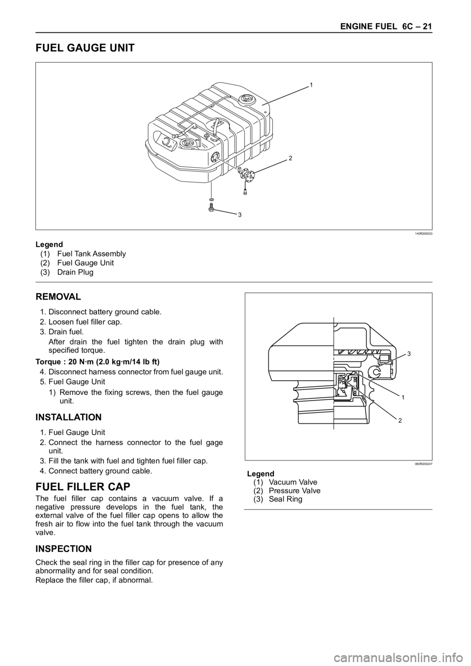
FUEL GAUGE UNIT
1
2
3
140R200033
REMOVAL
1. Disconnect battery ground cable.
2. Loosen fuel filler cap.
3. Drain fuel.
After drain the fuel tighten the drain plug with
specified torque.
Torque : 20 Nꞏm (2.0 kgꞏm/14 lb ft)
4. Disconnect harness connector from fuel gauge unit.
5. Fuel Gauge Unit
1) Remove the fixing screws, then the fuel gauge
unit.
INSTALLATION
1. Fuel Gauge Unit
2. Connect the harness connector to the fuel gage
unit.
3. Fill the tank with fuel and tighten fuel filler cap.
4. Connect battery ground cable.
FUEL FILLER CAP
The fuel filler cap contains a vacuum valve. If a
negative pressure develops in the fuel tank, the
external valve of the fuel filler cap opens to allow the
fresh air to flow into the fuel tank through the vacuum
valve.
INSPECTION
Check the seal ring in the filler cap for presence of any
abnormality and for seal condition.
Replace the filler cap, if abnormal.Legend
(1) Vacuum Valve
(2) Pressure Valve
(3) Seal Ring Legend
(1) Fuel Tank Assembly
(2) Fuel Gauge Unit
(3) Drain Plug
1
3
2
060R200247
Page 1874 of 6000
ENGINE ELECTRICAL 6D – 7
ON-VEHICLE SERVICE
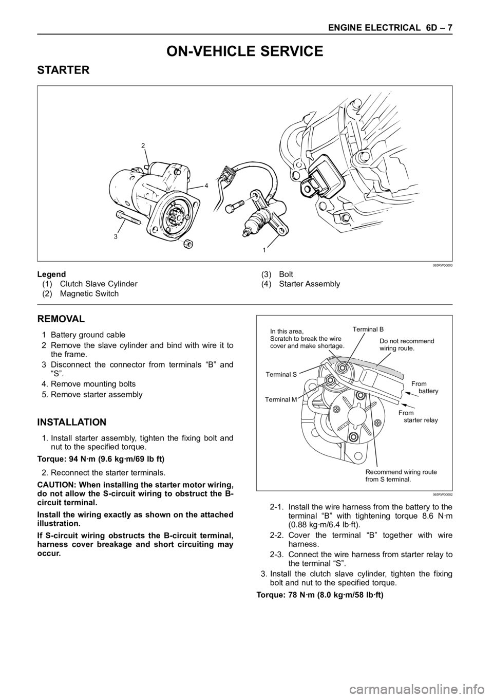
STARTER
REMOVAL
1 Battery ground cable
2 Remove the slave cylinder and bind with wire it to
the frame.
3 Disconnect the connector from terminals “B” and
“S”.
4. Remove mounting bolts
5. Remove starter assembly
INSTALLATION
1. Install starter assembly, tighten the fixing bolt and
nut to the specified torque.
Torque: 94 Nꞏm (9.6 kgꞏm/69 lb ft)
2. Reconnect the starter terminals.
CAUTION: When installing the starter motor wiring,
do not allow the S-circuit wiring to obstruct the B-
circuit terminal.
Install the wiring exactly as shown on the attached
illustration.
If S-circuit wiring obstructs the B-circuit terminal,
harness cover breakage and short circuiting may
occur.2-1. Install the wire harness from the battery to the
terminal “B” with tightening torque 8.6 Nꞏm
(0.88 kgꞏm/6.4 lbꞏft).
2-2. Cover the terminal “B” together with wire
harness.
2-3. Connect the wire harness from starter relay to
the terminal “S”.
3. Install the clutch slave cylinder, tighten the fixing
bolt and nut to the specified torque.
Torque: 78 Nꞏm (8.0 kgꞏm/58 lbꞏft)
1
32
4
Legend
(1) Clutch Slave Cylinder
(2) Magnetic Switch(3) Bolt
(4) Starter Assembly
065RW00003
Do not recommend
wiring route.
Recommend wiring route
from S terminal.From
battery
From
starter relay Terminal B
Terminal MTerminal SIn this area,
Scratch to break the wire
cover and make shortage.
065RW00002
Page 1889 of 6000
6D – 22 ENGINE ELECTRICAL
1. Using a press with a socket wrench attached,
reassemble rotor and rear end cover assembly in
the front cover.2. Install pulley on the rotor.
Secure the pulley directly in the vise between two
copper plates, and tighten nut to the specified
torque.
Torque: 111 Nꞏm (82 lb ft)
066RS022
066RS010
MAIN DATA AND SPECIFICATIONS
General Specifications
Model LR190-750B LR-1100-731
Battery voltage V 12
Rated output A 90 100
Direction of rotation Clockwise
(as viewed from pulley side)
Rated rotation speed rpm 5,000
Maximum speed rpm 18,000
Page 1892 of 6000
ENGINE ELECTRICAL 6D – 25
ECT SENSOR
Measure the resistance depending on the water
temperature.
Temperature (°C) Current (mA) Resistance (k
)
20 ± 1 1.0 2.0 – 3.0
50 ± 1 1.0 0.6 – 1.0
When installing the ECT sensor, apply sealant (Loctite
#262 or equivalent) to prevent water leakage.
Torque: 8 Nꞏm (0.8 kgꞏm/69 lb in)
Legend
(1) Sealing Material
GLOW PLUG
Inspect the resistance
Resistance at normal temperature: 0.8 – 1.0
Torque: 23 Nꞏm (2.3 kgꞏm/17 lbꞏft)
GLOW PLUG RELAY
Inspect the continuity
(2) – (4) No Continuity
(1) – (3) Continuity
If battery voltage is applied to the terminal between (1)
– (3)
(2) – (4) Continuity065RW058
065RW061
1
065RW060
2 42
311
34
065RW037
Page 1916 of 6000
6E–23 4JX1–TC ENGINE DRIVEABILITY AND EMISSIONS
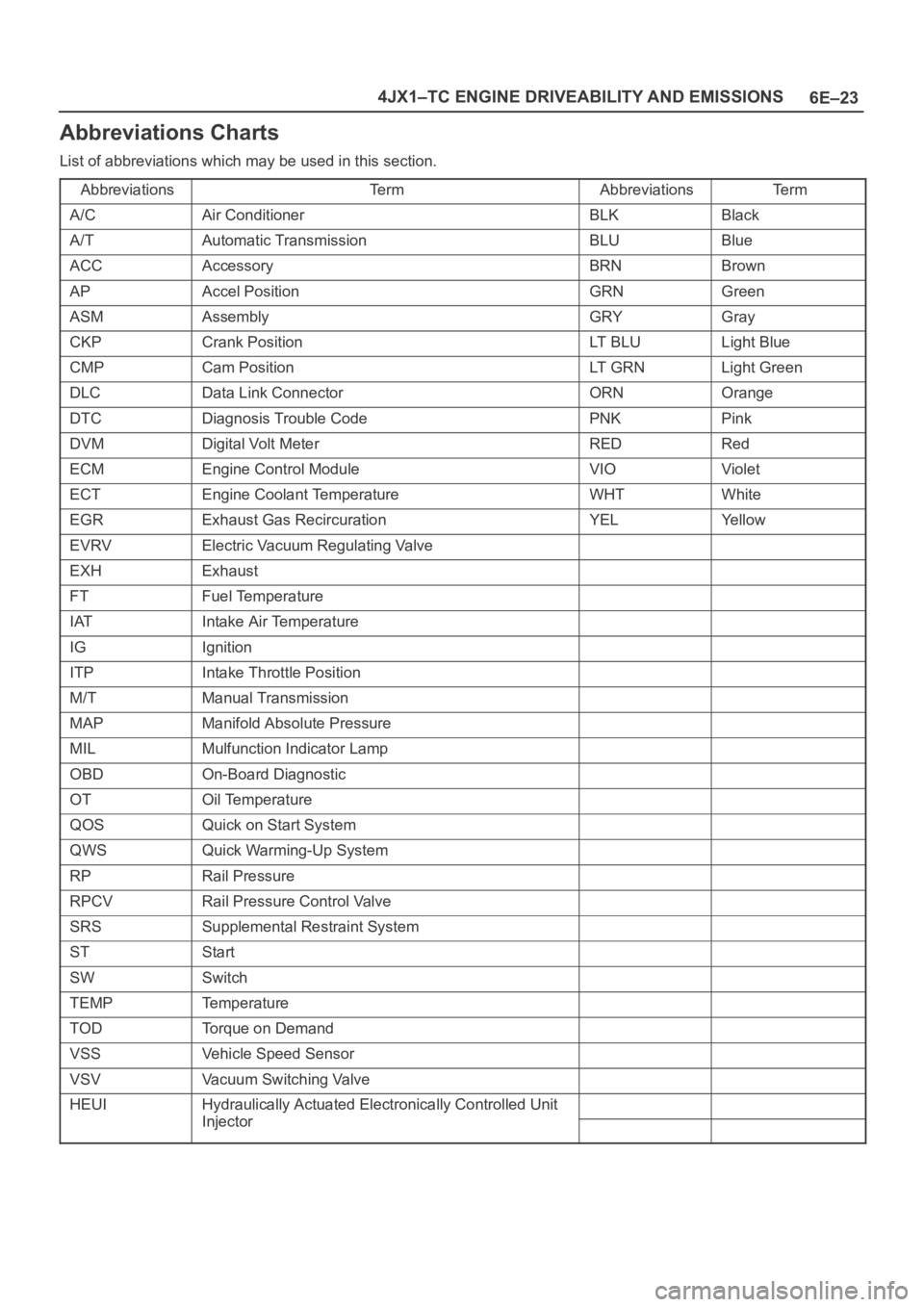
Abbreviations Charts
List of abbreviations which may be used in this section.
Abbreviations
Te r mAbbreviationsTe r m
A/CAir ConditionerBLKBlack
A/TAutomatic TransmissionBLUBlue
ACCAccessoryBRNBrown
APAccel PositionGRNGreen
ASMAssemblyGRYGray
CKPCrank PositionLT B L ULight Blue
CMPCam PositionLT G R NLight Green
DLCData Link ConnectorORNOrange
DTCDiagnosis Trouble CodePNKPink
DVMDigital Volt MeterREDRed
ECMEngine Control ModuleVIOViolet
ECTEngine Coolant TemperatureWHTWhite
EGRExhaust Gas RecircurationYELYe l l o w
EVRVElectric Vacuum Regulating Valve
EXHExhaust
FTFuel Temperature
IATIntake Air Temperature
IGIgnition
ITPIntake Throttle Position
M/TManual Transmission
MAPManifold Absolute Pressure
MILMulfunction Indicator Lamp
OBDOn-Board Diagnostic
OTOil Temperature
QOSQuick on Start System
QWSQuick Warming-Up System
RPRail Pressure
RPCVRail Pressure Control Valve
SRSSupplemental Restraint System
STStart
SWSwitch
TEMPTemperature
TODTorque on Demand
VSSVehicle Speed Sensor
VSVVacuum Switching Valve
HEUIHydraulically Actuated Electronically Controlled Unit
InjectorInjector