1998 OPEL FRONTERA air conditioning
[x] Cancel search: air conditioningPage 1456 of 6000
6E–339 ENGINE DRIVEABILITY AND EMISSIONS
0005
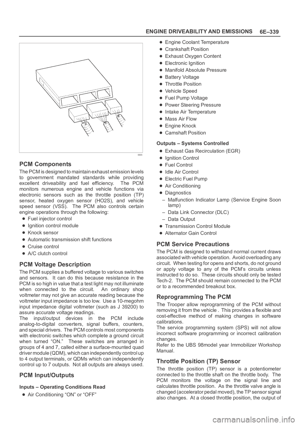
PCM Components
The PCM is designed to maintain exhaust emission levels
to government mandated standards while providing
excellent driveability and fuel efficiency. The PCM
monitors numerous engine and vehicle functions via
electronic sensors such as the throttle position (TP)
sensor, heated oxygen sensor (HO2S), and vehicle
speed sensor (VSS). The PCM also controls certain
engine operations through the following:
Fuel injector control
Ignition control module
Knock sensor
Automatic transmission shift functions
Cruise control
A/C clutch control
PCM Voltage Description
The PCM supplies a buffered voltage to various switches
and sensors. It can do this because resistance in the
PCM is so high in value that a test light may not illuminate
when connected to the circuit. An ordinary shop
voltmeter may not give an accurate reading because the
voltmeter input impedance is too low. Use a 10-megohm
input impedance digital voltmeter (such as J 39200) to
assure accurate voltage readings.
The input/output devices in the PCM include
analog-to-digital converters, signal buffers, counters,
and special drivers. The PCM controls most components
with electronic switches which complete a ground circuit
when turned “ON.” These switches are arranged in
groups of 4 and 7, called either a surface-mounted quad
driver module (QDM), which can independently control up
to 4 output terminals, or QDMs which can independently
control up to 7 outputs. Not all outputs are always used.
PCM Input/Outputs
Inputs – Operating Conditions Read
Air Conditioning “ON” or “OFF”
Engine Coolant Temperature
Crankshaft Position
Exhaust Oxygen Content
Electronic Ignition
Manifold Absolute Pressure
Battery Voltage
Throttle Position
Vehicle Speed
Fuel Pump Voltage
Power Steering Pressure
Intake Air Temperature
Mass Air Flow
Engine Knock
Camshaft Position
Outputs – Systems Controlled
Exhaust Gas Recirculation (EGR)
Ignition Control
Fuel Control
Idle Air Control
Electric Fuel Pump
Air Conditioning
Diagnostics
– Malfunction Indicator Lamp (Service Engine Soon
lamp)
– Data Link Connector (DLC)
– Data Output
Transmission Control Module
Alternator Gain Control
PCM Service Precautions
The PCM is designed to withstand normal current draws
associated with vehicle operation. Avoid overloading any
circuit. When testing for opens and shorts, do not ground
or apply voltage to any of the PCM’s circuits unless
instructed to do so. These circuits should only be tested
Tech-2. The PCM should remain connected to the PCM
or to a recommended breakout box.
Reprogramming The PCM
The Trooper allow reprogramming of the PCM without
removing it from the vehicle . This provides a flexible and
cost-effective method of making changes in software
calibrations.
The service programming system (SPS) will not allow
incorrect software programming or incorrect calibration
changes.
Refer to the UBS 98model year Immobilizer Workshop
Manual.
Throttle Position (TP) Sensor
The throttle position (TP) sensor is a potentiometer
connected to the throttle shaft on the throttle body. The
PCM monitors the voltage on the signal line and
calculates throttle position. As the throttle valve angle is
changed (accelerator pedal moved), the TP sensor signal
also changes. At a closed throttle position, the output of
Page 1899 of 6000
6E–6
4JX1–TC ENGINE DRIVEABILITY AND EMISSIONS
Removal Procedure 6E–212. . . . . . . . . . . . . . . . . . . .
Installation Procedure 6E–212. . . . . . . . . . . . . . . . . .
Fuel Filter Cap 6E–213. . . . . . . . . . . . . . . . . . . . . . . . . .
General Description 6E–213. . . . . . . . . . . . . . . . . . . .
Inspection Procedure 6E–213. . . . . . . . . . . . . . . . . .
Fuel Filter 6E–213. . . . . . . . . . . . . . . . . . . . . . . . . . . . . .
Removal and Installation Procedure 6E–213. . . . . .
Fuel Gauge Unit 6E–213. . . . . . . . . . . . . . . . . . . . . . . .
Removal Procedure 6E–213. . . . . . . . . . . . . . . . . . . .
Installation Procedure 6E–214. . . . . . . . . . . . . . . . . .
Fuel Injectors 6E–214. . . . . . . . . . . . . . . . . . . . . . . . . . .
Removal and Installation Procedure 6E–214. . . . . .
Fuel Temperature Sensor 6E–214. . . . . . . . . . . . . . . .
Removal Procedure 6E–214. . . . . . . . . . . . . . . . . . . .
Installation Procedure 6E–215. . . . . . . . . . . . . . . . . .
Rail Pressure (RP) Sensor 6E–216. . . . . . . . . . . . . . .
Removal Procedure 6E–216. . . . . . . . . . . . . . . . . . . .
Installation Procedure 6E–216. . . . . . . . . . . . . . . . . .
Fuel Tank 6E–216. . . . . . . . . . . . . . . . . . . . . . . . . . . . . .
Removal Procedure 6E–216. . . . . . . . . . . . . . . . . . . .
Throttle Body (TB) 6E–217. . . . . . . . . . . . . . . . . . . . . . .
Removal Procedure 6E–217. . . . . . . . . . . . . . . . . . . .
Installation Procedure 6E–217. . . . . . . . . . . . . . . . . .
Air Conditioning (A/C) Relay 6E–217. . . . . . . . . . . . . .
Removal Procedure 6E–217. . . . . . . . . . . . . . . . . . . .
Installation Procedure 6E–217. . . . . . . . . . . . . . . . . .
Exhaust Gas Recirculation (EGR) Vacuum
Switch Valve (VSV) 6E–217. . . . . . . . . . . . . . . . . . . . .
Removal Procedure 6E–217. . . . . . . . . . . . . . . . . . . .
Installation Procedure 6E–218. . . . . . . . . . . . . . . . . .
Electronic Vacuum Regurating Valve (EVRV) 6E–219
Removal Procedure 6E–219. . . . . . . . . . . . . . . . . . . .
Installation Procedure 6E–220. . . . . . . . . . . . . . . . . .
Wiring and Connectors 6E–220. . . . . . . . . . . . . . . . . . .
Wiring Harness Service 6E–220. . . . . . . . . . . . . . . .
Connectors and Terminals 6E–220. . . . . . . . . . . . . .
Wire Harness Repair: Twisted Shielded
Cable 6E–220. . . . . . . . . . . . . . . . . . . . . . . . . . . . . . . . .
Removal Procedure 6E–220. . . . . . . . . . . . . . . . . . . .
Installation Procedure 6E–221. . . . . . . . . . . . . . . . . .
Twisted Leads 6E–221. . . . . . . . . . . . . . . . . . . . . . . . . .
Removal Procedure 6E–221. . . . . . . . . . . . . . . . . . . .
Installation Procedure 6E–222. . . . . . . . . . . . . . . . . .
Weather-Pack Connector 6E–223. . . . . . . . . . . . . . . . .
Tools Required 6E–223. . . . . . . . . . . . . . . . . . . . . . . .
Removal Procedure 6E–223. . . . . . . . . . . . . . . . . . . . Installation Procedure 6E–223. . . . . . . . . . . . . . . . . .
Com-Pack III 6E–224. . . . . . . . . . . . . . . . . . . . . . . . . . .
General Information 6E–224. . . . . . . . . . . . . . . . . . . .
Metri-Pack 6E–224. . . . . . . . . . . . . . . . . . . . . . . . . . . . .
Tools Required 6E–224. . . . . . . . . . . . . . . . . . . . . . . .
Removal Procedure 6E–224
. . . . . . . . . . . . . . . . . . . .
Installation Procedure 6E–224. . . . . . . . . . . . . . . . . .
General Description
(ECM and Sensors) 6E–225. . . . . . . . . . . . . . . . . . . . .
57X Reference ECM Input 6E–225. . . . . . . . . . . . . .
A/C Request Signal 6E–225. . . . . . . . . . . . . . . . . . . .
Crankshaft Position (CKP) Sensor 6E–225. . . . . . .
Camshaft Position (CMP) Sensor and
Signal 6E–225. . . . . . . . . . . . . . . . . . . . . . . . . . . . . . .
Engine Coolant Temperature (ECT) Sensor 6E–225
Electrically Erasable Programmable Read
Only Memory (EEPROM) 6E–225. . . . . . . . . . . . . .
Intake Air Temperature (IAT) Sensor 6E–225. . . . .
Manifold Absolute Pressure (MAP) Sensor 6E–226
Engine Control Module (ECM) 6E–226. . . . . . . . . . .
ECM Function 6E–226. . . . . . . . . . . . . . . . . . . . . . . . .
ECM Components 6E–226. . . . . . . . . . . . . . . . . . . . .
ECM Voltage Description 6E–226. . . . . . . . . . . . . . .
ECM Input/Outputs 6E–226. . . . . . . . . . . . . . . . . . . .
ECM Service Precautions 6E–227. . . . . . . . . . . . . .
Intake Throttle Position (ITP) Sensor 6E–227. . . . .
Transmission Range Switch 6E–227. . . . . . . . . . . . .
Accelerator Position Sensor (AP) 6E–227. . . . . . . .
Aftermarket Electrical and Vacuum
Equipment 6E–227. . . . . . . . . . . . . . . . . . . . . . . . . . .
Electrostatic Discharge Damage 6E–227. . . . . . . . .
General Description (Air Induction) 6E–228. . . . . . . .
Air Induction System 6E–228. . . . . . . . . . . . . . . . . . .
General Description (Fuel Metering) 6E–228. . . . . . .
Deceleration Mode 6E–228. . . . . . . . . . . . . . . . . . . .
Fuel Injector 6E–228. . . . . . . . . . . . . . . . . . . . . . . . . .
Fuel Metering System Components 6E–228. . . . . .
A/C Clutch Diagnosis 6E–228. . . . . . . . . . . . . . . . . . . .
A/C Request Signal 6E–228. . . . . . . . . . . . . . . . . . . .
General Description Exhaust Gas
Recirculation (EGR) System 6E–228. . . . . . . . . . . . .
EGR Purpose 6E–228. . . . . . . . . . . . . . . . . . . . . . . . .
Fuse and Relay Panel
(Underhood Electrical Center) RHD 6E–229. . . . . . .
Fuse and Relay Panel
(Underhood Electrical Center) LHD 6E–230. . . . . . .
Page 1934 of 6000
6E–41 4JX1–TC ENGINE DRIVEABILITY AND EMISSIONS
EGR (Exhaust Gas Recirculation)
Diagnosis
A diagnosis of the EGR system is covered by DTC
P1403.
EGR VSV circuit diagnosis is covered by DTC P1404.
EGR pressure sensor diagnosis is covered by DTC
P405 and/or P406.
EGR EVRV circuit diagnosis is covered by DTC
P1405. Refer to the DTC charts.
Tech 2 Data Definitions and Ranges
A/C CLUTCH–Tech 2 Displays ON or OFF–
Indicates whether the A/C has commanded the A/C
clutch ON.
MAP kPa — Tech 2 Range 10-105 kPa/0.00-5.00
Vo l t s —
The manifold absolute pressure reading is determined
from the MAP sensor signal monitored during key up and
wide open throttle (WOT) conditions. The manifold
absolute pressure is used to compensate for altitude
differences and is normally displayed around “61-104”
depending on altitude and manifold absolute pressure.
CMP ACT. COUNTER –Cam Position
DESIRED IDLE — Tech 2 Range 0-3187 RPM —
The idle speed that the ECM is commanding. The ECM
will compensate for various engine loads based on engine
coolant temperature, to keep the engine at the desired
speed.
ECT — (Engine Coolant Temperature) Tech 2
Range –40
C to 151C (–40F to 304F) —
The engine coolant temperature (ECT) is mounted in the
coolant stream and sends engine temperature
information to the ECM. The ECM applies 5 volts to the
ECT sensor circuit. The sensor is a thermistor which
changes internal resistance as temperature changes.
When the sensor is cold (high resistance), the ECM
monitors a high signal voltage and interprets that as a cold
engine. As the sensor warms (decreasing resistance),
the voltage signal will decrease and the ECM will interpret
the lower voltage as a warm engine.
ENGINE RUN TIME — Tech 2 Range
00:00:00-99:99:99 Hrs:Min:Sec —
Indicates the time elapsed since the engine was started.
If the engine is stopped, engine run time will be reset to
00:00:00.
ENGINE SPEED — Range 0-9999 RPM —
Engine speed is computed by the ECM from the 57X
reference input. It should remain close to desired idle
under various engine loads with engine idling.Air Intake Valve meter POSITION — Tech 2 Range
0-100 % —
IAT (INTAKE AIR TEMPERATURE)— Tech 2 Range
–40
C to 151C (–40F to 304F) —
The ECM converts the resistance of the intake air
temperature sensor to degrees. Intake air temperature
(IAT) is used by the ECM to adjust fuel delivery and spark
timing according to incoming air density.
MAP — Tech 2 Range 10-105 kPa (0.00-4.97 Volts)—
The manifold absolute pressure (MAP) sensor measures
the change in the boost pressure.
MIL — Tech 2 Displays ON or OFF —
Indicates the ECM commanded state of the malfunction
indicator lamp.
AP — Tech 2 Range 0%-100% —
AP (Accelerator position) angle is computed by the ECM
from the AP sensor voltage. AP angle should display
“0%” at idle and “100%” at wide open throttle.
AP SENSOR — Tech 2 Range 0.00-5.00 Volts —
The voltage being monitored by the ECM on the AP
sensor signal circuit.
VEHICLE SPEED—Tech 2 Range 0-255 km/h (0-155
mph)–
The vehicle speed sensor signal is converted into km/h
and mph for display.
Typical Scan Data Values
Use the Typical Scan Data Values Table only after the
On-Board Diagnostic System Check has been
completed, no DTC(s) were noted, and you have
determined that the on-board diagnostics are functioning
properly. Tech 2 values from a properly-running engine
may be used for comparison with the engine you are
diagnosing. The typical scan data values represent
values that would be seen on a normally-running engine.
NOTE: A Tech 2 that displays faulty data should not be
used, and the problem should be reported to the Tech 2
manufacturer. Use of a faulty Tech 2 can result in
misdiagnosis and unnecessary replacement of parts.
Only the parameters listed below are referred to in this
service manual for use in diagnosis. For further
information on using the Tech 2 to diagnose the ECM and
related sensors, refer to the applicable reference section
listed below. If all values are within the typical range
described below, refer to the
Symptoms section for
diagnosis.
Test Conditions
Engine running, lower radiator hose hot, transmission in
park or neutral, accessaries off, brake not applied and air
conditioning off.
Page 2110 of 6000
6E–217 4JX1–TC ENGINE DRIVEABILITY AND EMISSIONS
Throttle Body (TB)
Removal Procedure
1. Disconnect the negative battery cable.
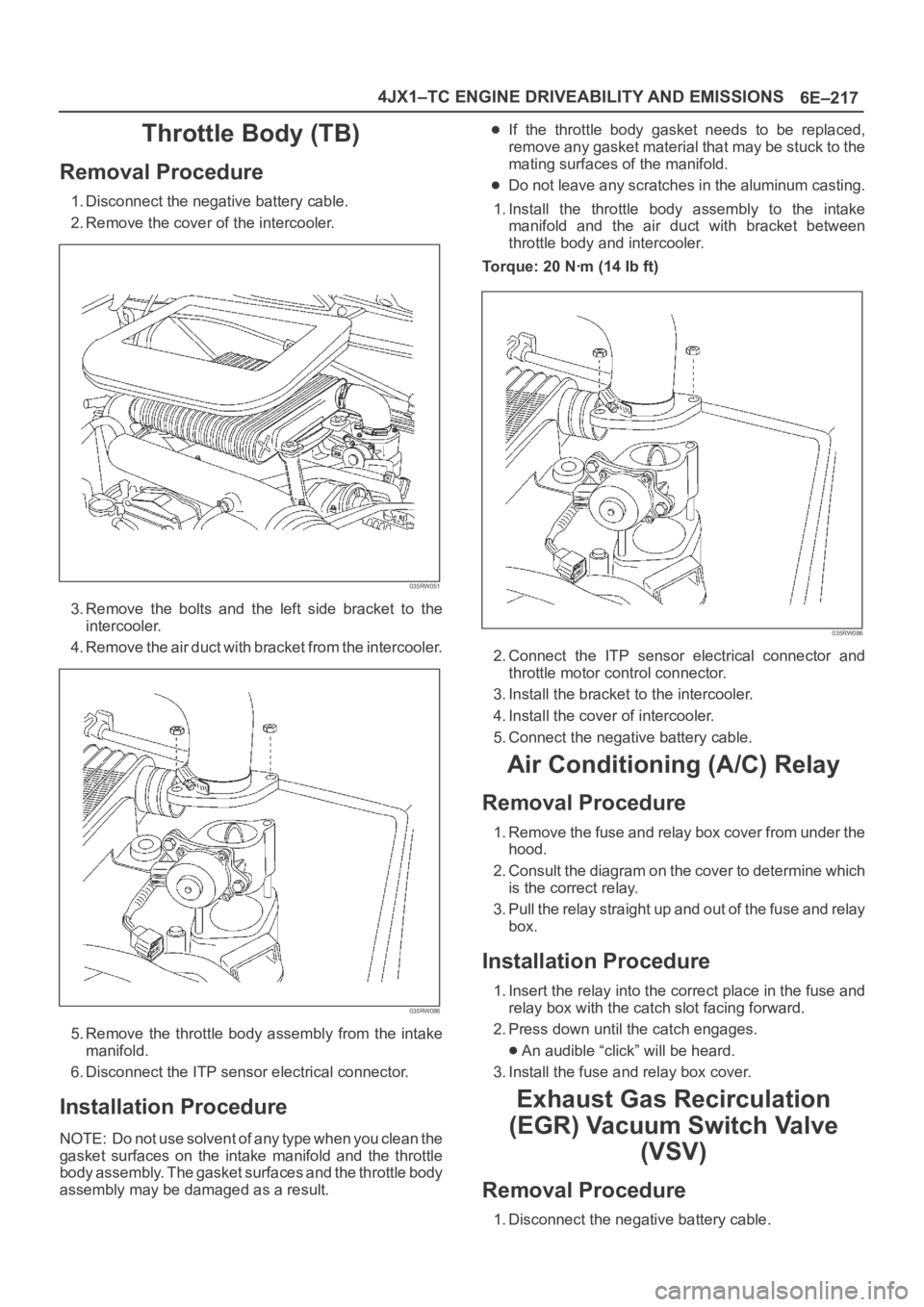
2. Remove the cover of the intercooler.
035RW051
3. Remove the bolts and the left side bracket to the
intercooler.
4 . R e m o v e t h e a i r d u c t w i t h b r a c k e t f r o m t h e i n t e r c o o l e r.
035RW086
5. Remove the throttle body assembly from the intake
manifold.
6. Disconnect the ITP sensor electrical connector.
Installation Procedure
NOTE: Do not use solvent of any type when you clean the
gasket surfaces on the intake manifold and the throttle
body assembly. The gasket surfaces and the throttle body
assembly may be damaged as a result.
If the throttle body gasket needs to be replaced,
remove any gasket material that may be stuck to the
mating surfaces of the manifold.
Do not leave any scratches in the aluminum casting.
1. Install the throttle body assembly to the intake
manifold and the air duct with bracket between
throttle body and intercooler.
Torque: 20 Nꞏm (14 Ib ft)
035RW086
2. Connect the ITP sensor electrical connector and
throttle motor control connector.
3. Install the bracket to the intercooler.
4. Install the cover of intercooler.
5. Connect the negative battery cable.
Air Conditioning (A/C) Relay
Removal Procedure
1. Remove the fuse and relay box cover from under the
hood.
2. Consult the diagram on the cover to determine which
is the correct relay.
3. Pull the relay straight up and out of the fuse and relay
box.
Installation Procedure
1. Insert the relay into the correct place in the fuse and
relay box with the catch slot facing forward.
2. Press down until the catch engages.
An audible “click” will be heard.
3. Install the fuse and relay box cover.
Exhaust Gas Recirculation
(EGR) Vacuum Switch Valve
(VSV)
Removal Procedure
1. Disconnect the negative battery cable.
Page 2119 of 6000
6E–226
4JX1–TC ENGINE DRIVEABILITY AND EMISSIONS
0018
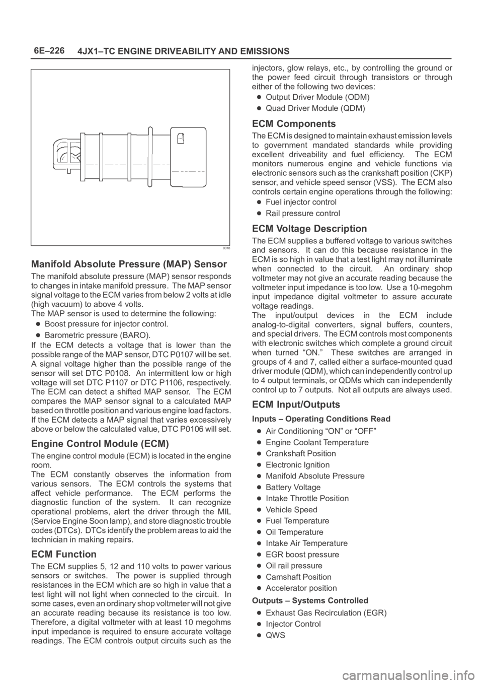
Manifold Absolute Pressure (MAP) Sensor
The manifold absolute pressure (MAP) sensor responds
to changes in intake manifold pressure. The MAP sensor
signal voltage to the ECM varies from below 2 volts at idle
(high vacuum) to above 4 volts.
The MAP sensor is used to determine the following:
Boost pressure for injector control.
Barometric pressure (BARO).
If the ECM detects a voltage that is lower than the
possible range of the MAP sensor, DTC P0107 will be set.
A signal voltage higher than the possible range of the
sensor will set DTC P0108. An intermittent low or high
voltage will set DTC P1107 or DTC P1106, respectively.
The ECM can detect a shifted MAP sensor. The ECM
compares the MAP sensor signal to a calculated MAP
based on throttle position and various engine load factors.
If the ECM detects a MAP signal that varies excessively
above or below the calculated value, DTC P0106 will set.
Engine Control Module (ECM)
The engine control module (ECM) is located in the engine
room.
The ECM constantly observes the information from
various sensors. The ECM controls the systems that
affect vehicle performance. The ECM performs the
diagnostic function of the system. It can recognize
operational problems, alert the driver through the MIL
(Service Engine Soon lamp), and store diagnostic trouble
codes (DTCs). DTCs identify the problem areas to aid the
technician in making repairs.
ECM Function
The ECM supplies 5, 12 and 110 volts to power various
sensors or switches. The power is supplied through
resistances in the ECM which are so high in value that a
test light will not light when connected to the circuit. In
some cases, even an ordinary shop voltmeter will not give
an accurate reading because its resistance is too low.
Therefore, a digital voltmeter with at least 10 megohms
input impedance is required to ensure accurate voltage
readings. The ECM controls output circuits such as theinjectors, glow relays, etc., by controlling the ground or
the power feed circuit through transistors or through
either of the following two devices:
Output Driver Module (ODM)
Quad Driver Module (QDM)
ECM Components
The ECM is designed to maintain exhaust emission levels
to government mandated standards while providing
excellent driveability and fuel efficiency. The ECM
monitors numerous engine and vehicle functions via
electronic sensors such as the crankshaft position (CKP)
sensor, and vehicle speed sensor (VSS). The ECM also
controls certain engine operations through the following:
Fuel injector control
Rail pressure control
ECM Voltage Description
The ECM supplies a buffered voltage to various switches
and sensors. It can do this because resistance in the
ECM is so high in value that a test light may not illuminate
when connected to the circuit. An ordinary shop
voltmeter may not give an accurate reading because the
voltmeter input impedance is too low. Use a 10-megohm
input impedance digital voltmeter to assure accurate
voltage readings.
The input/output devices in the ECM include
analog-to-digital converters, signal buffers, counters,
and special drivers. The ECM controls most components
with electronic switches which complete a ground circuit
when turned “ON.” These switches are arranged in
groups of 4 and 7, called either a surface-mounted quad
driver module (QDM), which can independently control up
to 4 output terminals, or QDMs which can independently
control up to 7 outputs. Not all outputs are always used.
ECM Input/Outputs
Inputs – Operating Conditions Read
Air Conditioning “ON” or “OFF”
Engine Coolant Temperature
Crankshaft Position
Electronic Ignition
Manifold Absolute Pressure
Battery Voltage
Intake Throttle Position
Vehicle Speed
Fuel Temperature
Oil Temperature
Intake Air Temperature
EGR boost pressure
Oil rail pressure
Camshaft Position
Accelerator position
Outputs – Systems Controlled
Exhaust Gas Recirculation (EGR)
Injector Control
QWS
Page 2255 of 6000
7A1–10
TRANSMISSION CONTROL SYSTEM (4L30–E)
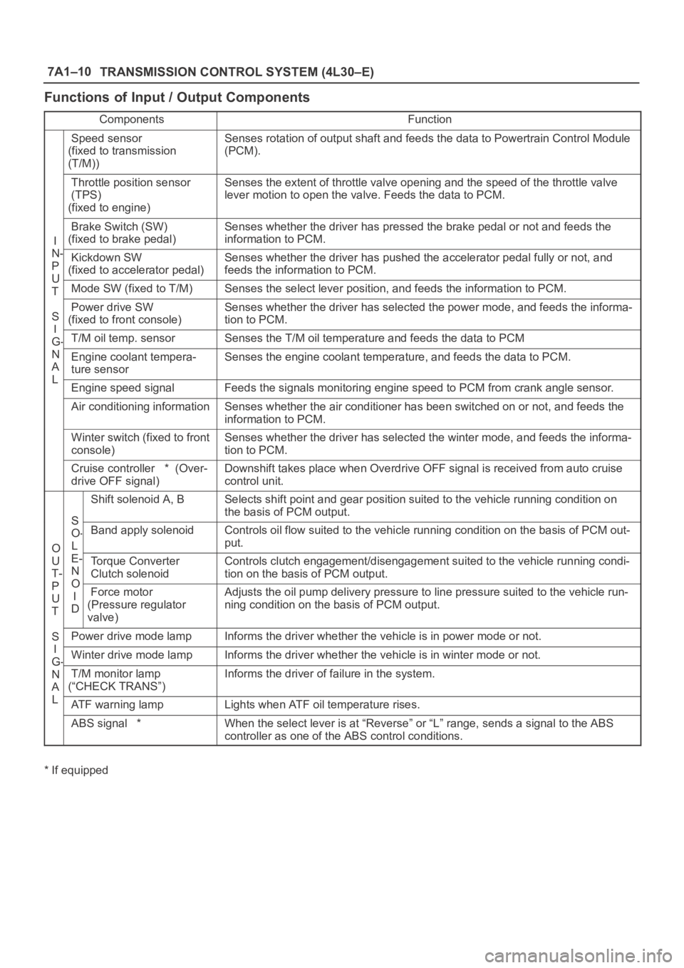
Functions of Input / Output Components
ComponentsFunction
Speed sensor
(fixed to transmission
(T/M))Senses rotation of output shaft and feeds the data to Powertrain Control Module
(PCM).
Throttle position sensor
(TPS)
(fixed to engine)Senses the extent of throttle valve opening and the speed of the throttle valve
lever motion to open the valve. Feeds the data to PCM.
I
N
Brake Switch (SW)
(fixed to brake pedal)Senses whether the driver has pressed the brake pedal or not and feeds the
information to PCM.
N-
P
U
Kickdown SW
(fixed to accelerator pedal)Senses whether the driver has pushed the accelerator pedal fully or not, and
feeds the information to PCM.
U
TMode SW (fixed to T/M)Senses the select lever position, and feeds the information to PCM.
S
I
Power drive SW
(fixed to front console)Senses whether the driver has selected the power mode, and feeds the informa-
tion to PCM.
I
G-T/M oil temp. sensorSenses the T/M oil temperature and feeds the data to PCM
N
A
L
Engine coolant tempera-
ture sensorSenses the engine coolant temperature, and feeds the data to PCM.
LEngine speed signalFeeds the signals monitoring engine speed to PCM from crank angle sensor.
Air conditioning informationSenses whether the air conditioner has been switched on or not, and feeds the
information to PCM.
Winter switch (fixed to front
console)Senses whether the driver has selected the winter mode, and feeds the informa-
tion to PCM.
Cruise controller * (Over-
drive OFF signal)Downshift takes place when Overdrive OFF signal is received from auto cruise
control unit.
S
Shift solenoid A, BSelects shift point and gear position suited to the vehicle running condition on
the basis of PCM output.
O
S
O-
L
Band apply solenoidControls oil flow suited to the vehicle running condition on the basis of PCM out-
put.
O
U
T-
P
E-
N
O
Torque Converter
Clutch solenoidControls clutch engagement/disengagement suited to the vehicle running condi-
tion on the basis of PCM output.
P
U
T
O
I
DForce motor
(Pressure regulator
valve)Adjusts the oil pump delivery pressure to line pressure suited to the vehicle run-
ning condition on the basis of PCM output.
S
I
Power drive mode lampInforms the driver whether the vehicle is in power mode or not.
I
G-Winter drive mode lampInforms the driver whether the vehicle is in winter mode or not.G
N
A
L
T/M monitor lamp
(“CHECK TRANS”)Informs the driver of failure in the system.
LATF warning lampLights when ATF oil temperature rises.
ABS signal *When the select lever is at “Reverse” or “L” range, sends a signal to the ABS
controller as one of the ABS control conditions.
* If equipped
Page 3248 of 6000
8F–53 BODY STRUCTURE
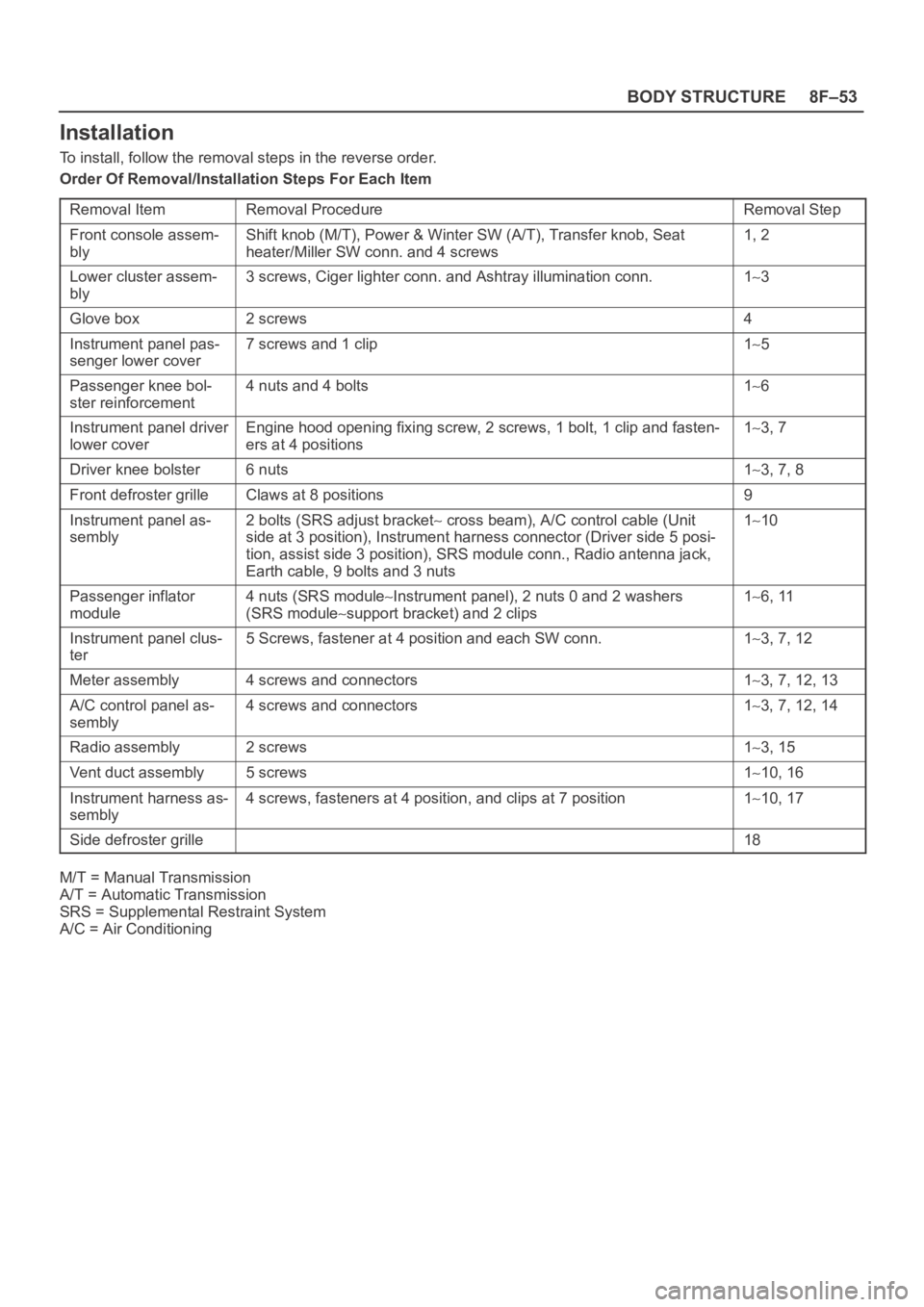
Installation
To install, follow the removal steps in the reverse order.
Order Of Removal/Installation Steps For Each Item
Removal Item
Removal ProcedureRemoval Step
Front console assem-
blyShift knob (M/T), Power & Winter SW (A/T), Transfer knob, Seat
heater/Miller SW conn. and 4 screws1, 2
Lower cluster assem-
bly3 screws, Ciger lighter conn. and Ashtray illumination conn.13
Glove box2 screws4
Instrument panel pas-
senger lower cover7 screws and 1 clip15
Passenger knee bol-
ster reinforcement4 nuts and 4 bolts16
Instrument panel driver
lower coverEngine hood opening fixing screw, 2 screws, 1 bolt, 1 clip and fasten-
ers at 4 positions13, 7
Driver knee bolster6 nuts13, 7, 8
Front defroster grilleClaws at 8 positions9
Instrument panel as-
sembly2 bolts (SRS adjust bracket cross beam), A/C control cable (Unit
side at 3 position), Instrument harness connector (Driver side 5 posi-
tion, assist side 3 position), SRS module conn., Radio antenna jack,
Earth cable, 9 bolts and 3 nuts110
Passenger inflator
module4 nuts (SRS moduleInstrument panel), 2 nuts 0 and 2 washers
(SRS module
support bracket) and 2 clips
16, 11
Instrument panel clus-
ter5 Screws, fastener at 4 position and each SW conn.13, 7, 12
Meter assembly4 screws and connectors13, 7, 12, 13
A/C control panel as-
sembly4 screws and connectors13, 7, 12, 14
Radio assembly2 screws13, 15
Vent duct assembly5 screws110, 16
Instrument harness as-
sembly4 screws, fasteners at 4 position, and clips at 7 position110, 17
Side defroster grille18
M/T = Manual Transmission
A/T = Automatic Transmission
SRS = Supplemental Restraint System
A/C = Air Conditioning
Page 3477 of 6000
SUPPLEMENTAL RESTRAINT SYSTEM 9J–40
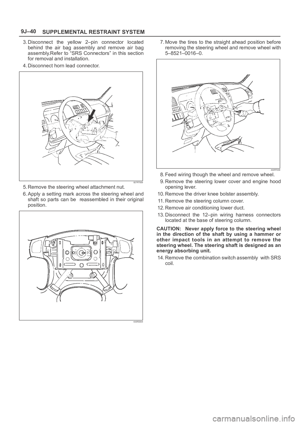
3. Disconnect the yellow 2–pin connector located
behind the air bag assembly and remove air bag
assembly.Refer to “SRS Connectors” in this section
for removal and installation.
4. Disconnect horn lead connector.
827RT009
5. Remove the steering wheel attachment nut.
6. Apply a setting mark across the steering wheel and
shaft so parts can be reassembled in their original
position.
430RS004
7. Move the tires to the straight ahead position before
removing the steering wheel and remove wheel with
5–8521–0016–0.
430RT009
8. Feed wiring though the wheel and remove wheel.
9. Remove the steering lower cover and engine hood
opening lever.
10. Remove the driver knee bolster assembly.
11. Remove the steering column cover.
12. Remove air conditioning lower duct.
13. Disconnect the 12–pin wiring harness connectors
located at the base of steering column.
CAUTION: Never apply force to the steering wheel
in the direction of the shaft by using a hammer or
other impact tools in an attempt to remove the
steering wheel. The steering shaft is designed as an
energy absorbing unit.
14. Remove the combination switch assembly with SRS
coil.