1998 OPEL FRONTERA air conditioning
[x] Cancel search: air conditioningPage 1120 of 6000
6E–3 ENGINE DRIVEABILITY AND EMISSIONS
Diagnostic Trouble Code (DTC) P0351
Ignition 1 Control Circuit 6E–206. . . . . . . . . . . . . . . . .
Diagnostic Trouble Code (DTC) P0352
Ignition 2 Control Circuit 6E–209. . . . . . . . . . . . . . . . .
Diagnostic Trouble Code (DTC) P0353
Ignition 3 Control Circuit 6E–212. . . . . . . . . . . . . . . . .
Diagnostic Trouble Code (DTC) P0354
Ignition 4 Control Circuit 6E–215. . . . . . . . . . . . . . . . .
Diagnostic Trouble Code (DTC) P0355
Ignition 5 Control Circuit 6E–218. . . . . . . . . . . . . . . . .
Diagnostic Trouble Code (DTC) P0356
Ignition 6 Control Circuit 6E–221. . . . . . . . . . . . . . . . .
Diagnostic Trouble Code (DTC) P0402
EGR Pintle Crank Error 6E–224. . . . . . . . . . . . . . . . . .
Diagnostic Trouble Code (DTC) P0404
EGR Open Stuck 6E–226. . . . . . . . . . . . . . . . . . . . . . .
Diagnostic Trouble Code (DTC) P0405
EGR Low Voltage 6E–228. . . . . . . . . . . . . . . . . . . . . . .
Diagnostic Trouble Code (DTC) P0406
EGR High Voltage 6E–231. . . . . . . . . . . . . . . . . . . . . .
Diagnostic Trouble Code (DTC) P0502
VSS Circuit Low Input 6E–234. . . . . . . . . . . . . . . . . . .
Diagnostic Trouble Code (DTC) P0562
System Voltage Low 6E–237. . . . . . . . . . . . . . . . . . . .
Diagnostic Trouble Code (DTC) P0563
System Voltage High 6E–239. . . . . . . . . . . . . . . . . . . .
Diagnostic Trouble Code (DTC) P0601
PCM Memory 6E–240. . . . . . . . . . . . . . . . . . . . . . . . . .
Diagnostic Trouble Code (DTC) P1154
HO2S Circuit Transition Time Ratio Bank 2
Sensor 1 6E–241. . . . . . . . . . . . . . . . . . . . . . . . . . . . . .
Diagnostic Trouble Code (DTC) P1171
Fuel System Lean During Acceleration 6E–245. . . .
Diagnostic Trouble Code (DTC) P1380
ABS Rough Road ABS System Fault 6E–248. . . . . .
Diagnostic Trouble Code (DTC) P1404
EGR Closed Stuck 6E–249. . . . . . . . . . . . . . . . . . . . . .
Diagnostic Trouble Code (DTC) P1508
IAC System Low RPM 6E–251. . . . . . . . . . . . . . . . . . .
Diagnostic Trouble Code (DTC) P1509
IAC System High RPM 6E–254. . . . . . . . . . . . . . . . . .
Diagnostic Trouble Code (DTC) P1618
Serial Peripheral Interface (SPI) PCM
Interprocessor Communication Error 6E–257. . . . . .
Diagnostic Trouble Code (DTC) P1625
PCM Unexpected Reset 6E–258. . . . . . . . . . . . . . . . .
Diagnostic Trouble Code (DTC) P1640
Driver-1-Input High Voltage 6E–259. . . . . . . . . . . . . .
Symptom Diagnosis 6E–262. . . . . . . . . . . . . . . . . . . . .
Default Matrix Table 6E–288. . . . . . . . . . . . . . . . . . . . .
Camshaft Position (CMP) Sensor 6E–291. . . . . . . . . .
Crankshaft Position (CKP) Sensor 6E–292. . . . . . . . .
Engine Coolant Temperature (ECT) Sensor 6E–292.
Heated Oxygen Sensor (HO2S) 6E–293. . . . . . . . . . .
Intake Air Temperature (IAT) Sensor 6E–295. . . . . . .
Knock Sensor (KS) 6E–296. . . . . . . . . . . . . . . . . . . . . . Mass Air Flow (MAF) Sensor 6E–297. . . . . . . . . . . . .
Manifold Absolute Pressure (MAP) Sensor 6E–297.
Malfunction Indicator Lamp (MIL) 6E–298. . . . . . . . . .
Powertrain Control Module (PCM) 6E–298. . . . . . . . .
EEPROM 6E–300. . . . . . . . . . . . . . . . . . . . . . . . . . . . . .
Power Steering Pressure (PSP) Switch 6E–300
. . . .
Throttle Position (TP) Sensor 6E–301. . . . . . . . . . . . .
Vehicle Speed Sensor (VSS) 6E–302. . . . . . . . . . . . .
Air Cleaner/Air Filter 6E–303. . . . . . . . . . . . . . . . . . . . .
Idle Air Control (IAC) Valve 6E–304. . . . . . . . . . . . . . .
Common Chamber 6E–305. . . . . . . . . . . . . . . . . . . . . .
Accelerator Cable Assembly 6E–305. . . . . . . . . . . . . .
Accelerator Pedal Replacement 6E–308. . . . . . . . . . .
Fuel Filter Cap 6E–310. . . . . . . . . . . . . . . . . . . . . . . . . .
Fuel Filter 6E–310. . . . . . . . . . . . . . . . . . . . . . . . . . . . . .
Fuel Gauge Unit 6E–313. . . . . . . . . . . . . . . . . . . . . . . .
Fuel Injectors 6E–314. . . . . . . . . . . . . . . . . . . . . . . . . . .
Fuel Pressure Regulator 6E–315. . . . . . . . . . . . . . . . .
Fuel Metering System 6E–317. . . . . . . . . . . . . . . . . . . .
Fuel Pump Assembly 6E–318. . . . . . . . . . . . . . . . . . . .
Fuel Pump Relay 6E–319. . . . . . . . . . . . . . . . . . . . . . . .
Fuel Rail Assembly 6E–319. . . . . . . . . . . . . . . . . . . . . .
Fuel Tank 6E–321. . . . . . . . . . . . . . . . . . . . . . . . . . . . . .
Throttle Body (TB) 6E–323. . . . . . . . . . . . . . . . . . . . . . .
Electronic Ignition System 6E–324. . . . . . . . . . . . . . . .
Catalytic Converter 6E–325. . . . . . . . . . . . . . . . . . . . . .
Air Conditioning Relay 6E–325. . . . . . . . . . . . . . . . . . .
EVAP Canister Hoses 6E–326. . . . . . . . . . . . . . . . . . . .
EVAP Canister 6E–326. . . . . . . . . . . . . . . . . . . . . . . . . .
EVAP Canister Purge Solenoid 6E–327. . . . . . . . . . . .
Fuel Tank Vent Valve 6E–328. . . . . . . . . . . . . . . . . . . .
Linear Exhaust Gas Recirculation
(EGR) Valve 6E–328. . . . . . . . . . . . . . . . . . . . . . . . . . .
Positive Crankcase Ventilation (PCV) Valve 6E–329.
Wiring and Connectors 6E–330. . . . . . . . . . . . . . . . . . .
PCM Connectors and Terminals 6E–330. . . . . . . . . . .
Wire Harness Repair: Twisted Shielded
Cable 6E–330. . . . . . . . . . . . . . . . . . . . . . . . . . . . . . . . .
Twisted Leads 6E–331. . . . . . . . . . . . . . . . . . . . . . . . . .
Weather-Pack Connector 6E–332. . . . . . . . . . . . . . . . .
Com-Pack III 6E–333. . . . . . . . . . . . . . . . . . . . . . . . . . .
Metri-Pack 6E–333. . . . . . . . . . . . . . . . . . . . . . . . . . . . .
General Description 6E–335. . . . . . . . . . . . . . . . . . . . .
General Description (PCM and Sensors) 6E–335. . .
58X Reference PCM Input 6E–335. . . . . . . . . . . . . .
A/C Request Signal 6E–335. . . . . . . . . . . . . . . . . . . .
Crankshaft Position (CKP) Sensor 6E–335. . . . . . .
Camshaft Position (CMP) Sensor and
Signal 6E–335. . . . . . . . . . . . . . . . . . . . . . . . . . . . . . .
Engine Coolant Temperature (ECT) Sensor 6E–335
Electrically Erasable Programmable Read
Only Memory (EEPROM) 6E–336. . . . . . . . . . . . . .
Fuel Control Heated Oxygen Sensors 6E–336. . . .
Intake Air Temperature (IAT) Sensor 6E–336. . . . .
Page 1171 of 6000
6E–54
ENGINE DRIVEABILITY AND EMISSIONS
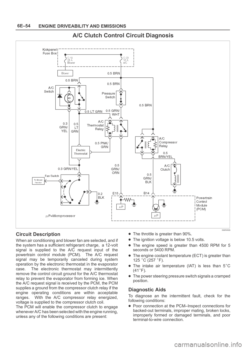
A/C Clutch Control Circuit Diagnosis
D06RW085
Circuit Description
When air conditioning and blower fan are selected, and if
the system has a sufficient refrigerant charge, a 12-volt
signal is supplied to the A/C request input of the
powertrain control module (PCM). The A/C request
signal may be temporarily canceled during system
operation by the electronic thermostat in the evaporator
case. The electronic thermostat may intermittently
remove the control circuit ground for the A/C thermostat
relay to prevent the evaporator from forming ice. When
the A/C request signal is received by the PCM, the PCM
supplies a ground from the compressor clutch relay if the
engine operating conditions are within acceptable
ranges. With the A/C compressor relay energized,
voltage is supplied to the compressor clutch coil.
The PCM will enable the compressor clutch to engage
whenever A/C has been selected with the engine running,
unless any of the following conditions are present:
The throttle is greater than 90%.
The ignition voltage is below 10.5 volts.
The engine speed is greater than 4500 RPM for 5
seconds or 5400 RPM.
The engine coolant temperature (ECT) is greater than
125
C (257 F).
The intake air temperature (IAT) is less than 5C
(41
F).
The power steering pressure switch signals a cramped
position.
Diagnostic Aids
To diagnose an the intermittent fault, check for the
following conditions:
Poor connection at the PCM–Inspect connections for
backed-out terminals, improper mating, broken locks,
improperly formed or damaged terminals, and poor
terminal-to-wire connection.
Page 1172 of 6000
6E–55 ENGINE DRIVEABILITY AND EMISSIONS
Damaged harness–Inspect the wiring harness for
damage. If the harness appears to OK, observe the
A/C clutch while moving connectors and wiring
harnesses related to the A/C. A sudden clutch
malfunction will indicate the source of the intermittent
fault.
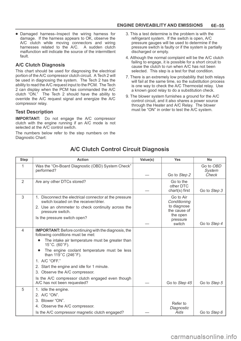
A/C Clutch Diagnosis
This chart should be used for diagnosing the electrical
p o r t i o n o f t h e A / C c o m p r e s s o r c l u t c h c i r c u i t . A Te c h 2 w i l l
be used in diagnosing the system. The Tech 2 has the
ability to read the A/C request input to the PCM. The Tech
2 can display when the PCM has commanded the A/C
clutch “ON.” The Tech 2 should have the ability to
override the A/C request signal and energize the A/C
compressor relay.
Test Description
IMPORTANT:Do not engage the A/C compressor
clutch with the engine running if an A/C mode is not
selected at the A/C control switch.
The numbers below refer to the step numbers on the
Diagnostic Chart:3. This a test determine is the problem is with the
refrigerant system. If the switch is open, A/C
pressure gauges will be used to determine if the
pressure switch is faulty or if the system is partially
discharged or empty.
4. Although the normal complaint will be the A/C clutch
failing to engage, it is possible for a short circuit to
cause the clutch to run when A/C has not been
selected. This step is a test for that condition.
7. There is an extremely low probability that both relays
will fail at the same time, so the substitution process
is one way to check the A/C Thermostat relay. Use
a known good relay to do a substitution check.
9. The blower system furnishes a ground for the A/C
control circuit, and it also shares a power source
through the Heater and A/C Relay. The blower
must be “ON” in order to test the A/C system.
A/C Clutch Control Circuit Diagnosis
StepActionVa l u e ( s )Ye sNo
1Was the “On-Board Diagnostic (OBD) System Check”
performed?
—Go to Step 2
Go to OBD
System
Check
2Are any other DTCs stored?
—
Go to the
other DTC
chart(s) first
Go to Step 3
31. Disconnect the electrical connector at the pressure
switch located on the receiver/drier.
2. Use an ohmmeter to check continuity across the
pressure switch.
Is the pressure switch open?
—
Go to Air
Conditioning
to diagnose
the cause of
the open
pressure
switch
Go to Step 4
4IMPORTANT:Before continuing with the diagnosis, the
following conditions must be met:
The intake air temperature must be greater than
15
C. (60F).
The engine coolant temperature must be less
than 119
C (246F).
1. A/C “OFF.”
2. Start the engine and idle for 1 minute.
3. Observe the A/C compressor.
Is the A/C compressor clutch engaged even though
A/C has not been requested?
—Go to Step 45Go to Step 5
51. Idle the engine.
2. A/C “ON”.
3. Blower “ON”.
4. Observe the A/C compressor.
Is the A/C compressor magnetic clutch engaged?
—
Refer to
Diagnostic
Aids
Go to Step 6
Page 1187 of 6000
6E–70
ENGINE DRIVEABILITY AND EMISSIONS
SPARK — Tech 2 Range –64 to 64 —
Displays the amount of spark advance being commanded
by the PCM on the IC circuit.
START-UP ECT — Tech 2 Range –40
C to 151C
(–40
F to 304F) —
Indicates the engine coolant temperature at the time that
the vehicle was started. Used by the HO2S diagnostic to
determine if the last start-up was a cold start.
START-UP IAT — Tech 2 Range –40
C to 151C
(–40
F to 304F) —
Indicates the intake air temperature at the time that the
vehicle was started. Used by the HO2S diagnostic to
determine if the last start-up was a cold start.
TP — Tech 2 Range 0%-100% —
TP (throttle position) angle is computed by the PCM from
the TP sensor voltage. TP angle should display “0%” at
idle and “100%” at wide open throttle.
TP SENSOR — Tech 2 Range 0.00-5.00 Volts —
The voltage being monitored by the PCM on the TP
sensor signal circuit.
CATALYST PROTECTION MODE — Tech 2 Displays
YES or NO —
“YES” displayed indicates that the PCM has detected
conditions appropriate to operate in TWC protection
mode. The PCM will decrease the air/fuel ratio to a value
that depends on mass air flow (higher mass air flow =
lower air/fuel ratio).
UPSHIFT LAMP (MANUAL TRANSMISSION)
VEHICLE SPEED — Tech 2 Range 0-255 km/h
(0-155 mph) —
The vehicle speed sensor signal is converted into km/h
and mph for display.
WEAK CYLINDER — Tech 2 Displays Cylinder
Number —
This indicates that the PCM has detected crankshaft
speed variations that indicate 2% or more cylinder firing
events are misfires.
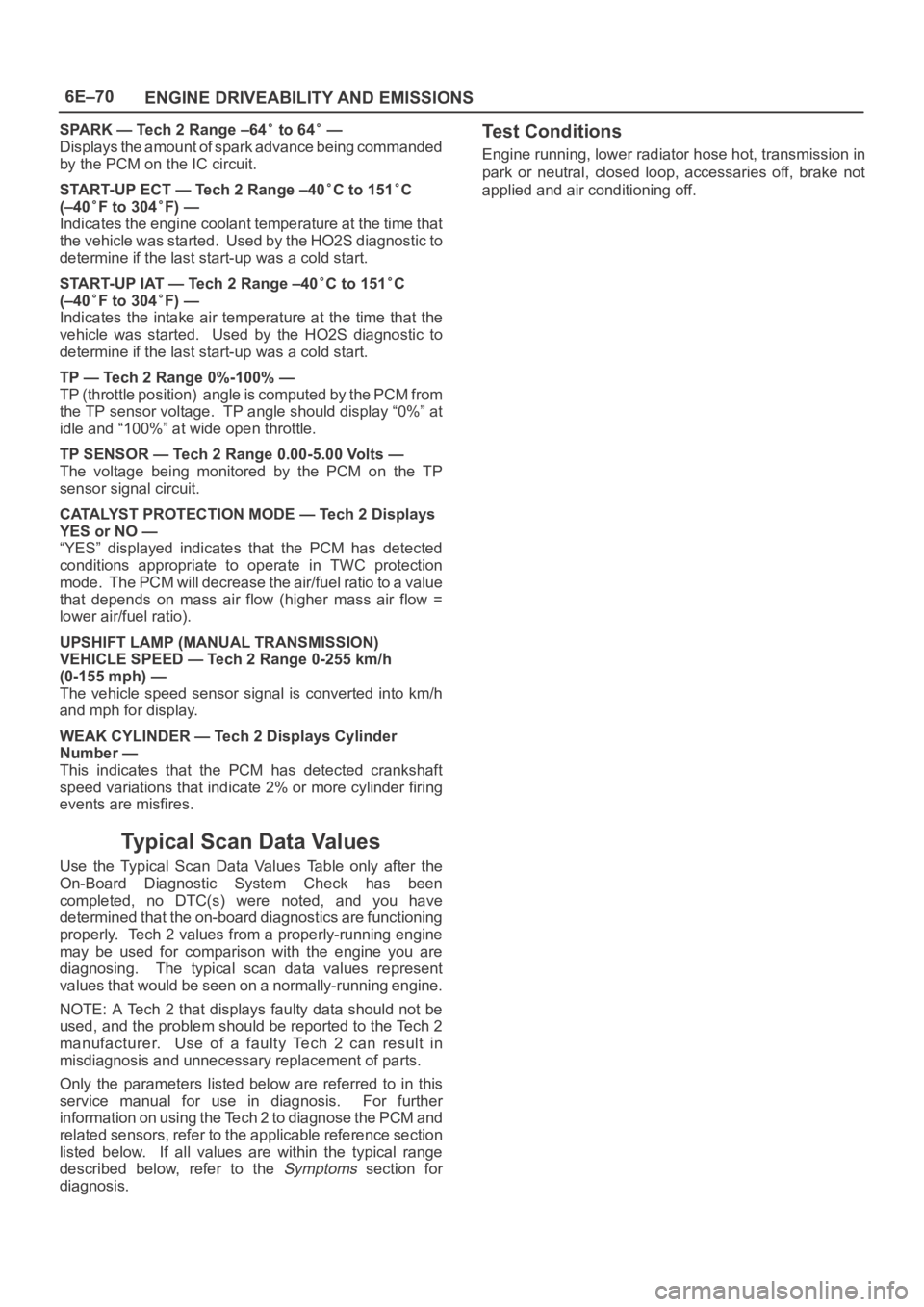
Typical Scan Data Values
Use the Typical Scan Data Values Table only after the
On-Board Diagnostic System Check has been
completed, no DTC(s) were noted, and you have
determined that the on-board diagnostics are functioning
properly. Tech 2 values from a properly-running engine
may be used for comparison with the engine you are
diagnosing. The typical scan data values represent
values that would be seen on a normally-running engine.
NOTE: A Tech 2 that displays faulty data should not be
used, and the problem should be reported to the Tech 2
manufacturer. Use of a faulty Tech 2 can result in
misdiagnosis and unnecessary replacement of parts.
Only the parameters listed below are referred to in this
service manual for use in diagnosis. For further
information on using the Tech 2 to diagnose the PCM and
related sensors, refer to the applicable reference section
listed below. If all values are within the typical range
described below, refer to the
Symptoms section for
diagnosis.
Test Conditions
Engine running, lower radiator hose hot, transmission in
park or neutral, closed loop, accessaries off, brake not
applied and air conditioning off.
Page 1207 of 6000
6E–90
ENGINE DRIVEABILITY AND EMISSIONS
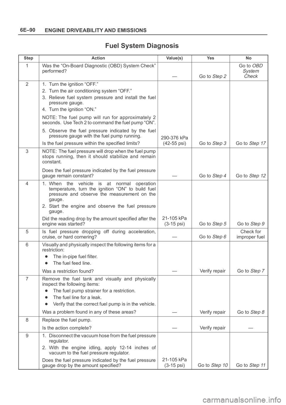
Fuel System Diagnosis
StepActionVa l u e ( s )Ye sNo
1Was the “On-Board Diagnostic (OBD) System Check”
performed?
—Go to Step 2
Go to OBD
System
Check
21. Turn the ignition “OFF.”
2. Turn the air conditioning system “OFF.”
3. Relieve fuel system pressure and install the fuel
pressure gauge.
4. Turn the ignition “ON.”
NOTE: The fuel pump will run for approximately 2
seconds. Use Tech 2 to command the fuel pump “ON”.
5. Observe the fuel pressure indicated by the fuel
pressure gauge with the fuel pump running.
Is the fuel pressure within the specified limits?
290-376 kPa
(42-55 psi)
Go to Step 3Go to Step 17
3NOTE: The fuel pressure will drop when the fuel pump
stops running, then it should stabilize and remain
constant.
Does the fuel pressure indicated by the fuel pressure
gauge remain constant?
—Go to Step 4Go to Step 12
41. When the vehicle is at normal operation
temperature, turn the ignition “ON” to build fuel
pressure and observe the measurement on the
gauge.
2. Start the engine and observe the fuel pressure
gauge.
Did the reading drop by the amount specified after the
engine was started?
21-105 kPa
(3-15 psi)
Go to Step 5Go to Step 9
5Is fuel pressure dropping off during acceleration,
cruise, or hard cornering?
—Go to Step 6
Check for
improper fuel
6Visually and physically inspect the following items for a
restriction:
The in-pipe fuel filter.
The fuel feed line.
Was a restriction found?
—Verify repairGo to Step 7
7Remove the fuel tank and visually and physically
inspect the following items:
The fuel pump strainer for a restriction.
The fuel line for a leak.
Verify that the correct fuel pump is in the vehicle.
Was a problem found in any of these areas?
—Verify repairGo to Step 8
8Replace the fuel pump.
Is the action complete?
—Verify repair—
91. Disconnect the vacuum hose from the fuel pressure
regulator.
2. With the engine idling, apply 12-14 inches of
vacuum to the fuel pressure regulator.
Does the fuel pressure indicated by the fuel pressure
gauge drop by the amount specified?
21-105 kPa
(3-15 psi)
Go to Step 10Go to Step 11
Page 1211 of 6000

6E–94
ENGINE DRIVEABILITY AND EMISSIONS
Idle Air Control (IAC) System Check
StepActionVa l u e ( s )Ye sNo
11. Ignition “OFF.”
2. Connect the Tech 2.
3. Set the parking brake.
4. Block the wheels.
5. Turn the air conditioning “OFF.”
6. Idle the engine in Park (A/T) or Neutral (M/T).
7. Operate the IAC test.
8. The engine speed should decrease and increase as
the IAC is cycled.
Does the RPM change?
—Go to Step 2Go to Step 3
2RPM should change smoothly.
Does the RPM change within the range specified?700-1500
RPM
—Go to Step 3
3Check the IAC passages.
Are the IAC passages OK?
—Go to Step 4Go to Step 5
4Clear any obstruction from the IAC passages.
Is the action complete?
—Verify repair—
5Replace the IAC. Refer to On-Vehicle Service, Idle Air
Control Valve.
Is the action complete?—Verify repair—
Page 1376 of 6000
6E–259 ENGINE DRIVEABILITY AND EMISSIONS
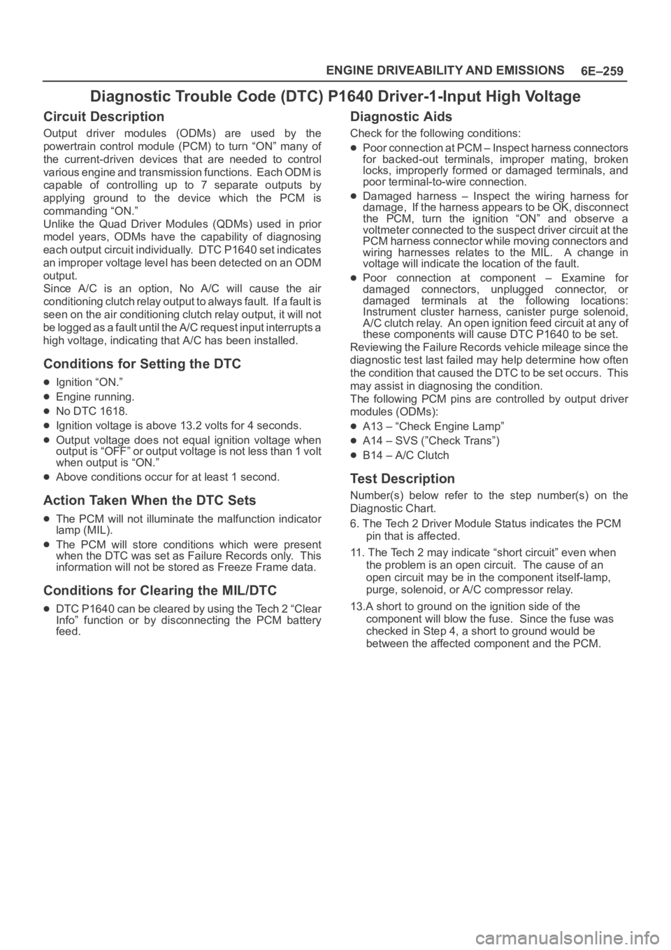
Diagnostic Trouble Code (DTC) P1640 Driver-1-Input High Voltage
Circuit Description
Output driver modules (ODMs) are used by the
powertrain control module (PCM) to turn “ON” many of
the current-driven devices that are needed to control
various engine and transmission functions. Each ODM is
capable of controlling up to 7 separate outputs by
applying ground to the device which the PCM is
commanding “ON.”
Unlike the Quad Driver Modules (QDMs) used in prior
model years, ODMs have the capability of diagnosing
each output circuit individually. DTC P1640 set indicates
an improper voltage level has been detected on an ODM
output.
Since A/C is an option, No A/C will cause the air
conditioning clutch relay output to always fault. If a fault is
seen on the air conditioning clutch relay output, it will not
be logged as a fault until the A/C request input interrupts a
high voltage, indicating that A/C has been installed.
Conditions for Setting the DTC
Ignition “ON.”
Engine running.
No DTC 1618.
Ignition voltage is above 13.2 volts for 4 seconds.
Output voltage does not equal ignition voltage when
output is “OFF” or output voltage is not less than 1 volt
when output is “ON.”
Above conditions occur for at least 1 second.
Action Taken When the DTC Sets
The PCM will not illuminate the malfunction indicator
lamp (MIL).
The PCM will store conditions which were present
when the DTC was set as Failure Records only. This
information will not be stored as Freeze Frame data.
Conditions for Clearing the MIL/DTC
DTC P1640 can be cleared by using the Tech 2 “Clear
Info” function or by disconnecting the PCM battery
feed.
Diagnostic Aids
Check for the following conditions:
Poor connection at PCM – Inspect harness connectors
for backed-out terminals, improper mating, broken
locks, improperly formed or damaged terminals, and
poor terminal-to-wire connection.
Damaged harness – Inspect the wiring harness for
damage, If the harness appears to be OK, disconnect
the PCM, turn the ignition “ON” and observe a
voltmeter connected to the suspect driver circuit at the
PCM harness connector while moving connectors and
wiring harnesses relates to the MIL. A change in
voltage will indicate the location of the fault.
Poor connection at component – Examine for
damaged connectors, unplugged connector, or
damaged terminals at the following locations:
Instrument cluster harness, canister purge solenoid,
A/C clutch relay. An open ignition feed circuit at any of
these components will cause DTC P1640 to be set.
Reviewing the Failure Records vehicle mileage since the
diagnostic test last failed may help determine how often
the condition that caused the DTC to be set occurs. This
may assist in diagnosing the condition.
The following PCM pins are controlled by output driver
modules (ODMs):
A13 – “Check Engine Lamp”
A14 – SVS (”Check Trans”)
B14 – A/C Clutch
Test Description
Number(s) below refer to the step number(s) on the
Diagnostic Chart.
6. The Tech 2 Driver Module Status indicates the PCM
pin that is affected.
11. The Tech 2 may indicate “short circuit” even when
the problem is an open circuit. The cause of an
open circuit may be in the component itself-lamp,
purge, solenoid, or A/C compressor relay.
13.A short to ground on the ignition side of the
component will blow the fuse. Since the fuse was
checked in Step 4, a short to ground would be
between the affected component and the PCM.
Page 1442 of 6000
6E–325 ENGINE DRIVEABILITY AND EMISSIONS
Spark Plug Gap Check
Check the gap of all spark plugs before installation.
Use a round wire feeler gauge to ensure an accurate
check.
Plugs installed with the wrong gap can cause poor
engine performance and excessive emissions.
Installation Procedure
NOTE: The plug must thread smoothly into the cylinder
head and be fully seated. Use a thread chaser if
necessary to clean the threads in the cylinder head.
Cross-threading or failure to fully seat the spark plug can
cause plug overheating, exhaust blow-by gas, or thread
damage. Do not overtighten the spark plugs. Over
tightening can cause aluminum threads to strip.
1. Install the spark plug in the engine. Use the
appropriate spark plug socket.
Tighten
Tighten the spark plug to 18 Nꞏm (13 lb ft.).
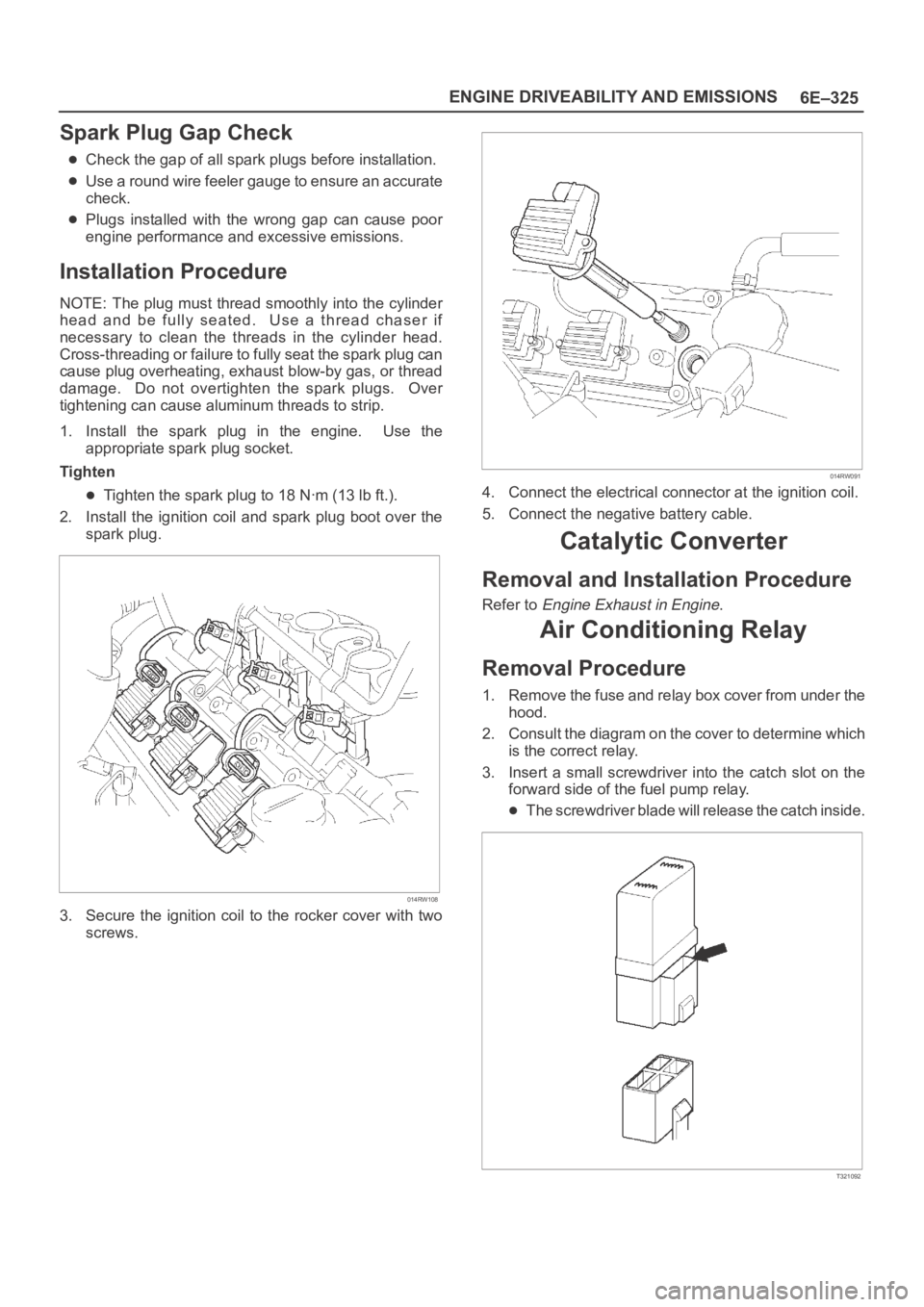
2. Install the ignition coil and spark plug boot over the
spark plug.
014RW108
3. Secure the ignition coil to the rocker cover with two
screws.
014RW091
4. Connect the electrical connector at the ignition coil.
5. Connect the negative battery cable.
Catalytic Converter
Removal and Installation Procedure
Refer to Engine Exhaust in Engine.
Air Conditioning Relay
Removal Procedure
1. Remove the fuse and relay box cover from under the
hood.
2. Consult the diagram on the cover to determine which
is the correct relay.
3. Insert a small screwdriver into the catch slot on the
forward side of the fuel pump relay.
The screwdriver blade will release the catch inside.
T321092