1998 OPEL FRONTERA ECO mode
[x] Cancel search: ECO modePage 856 of 6000

5A–46
BRAKE CONTROL SYSTEM
Chart B-6 Abnormal Transmission Input (DTC 23)
StepActionYe sNo
11. Turn the key off.
2. Disconnect EHCU connector.
Is there continuity between EHCU connector terminal 6 to 15
(Gear position-P(A/T), N(M/T))?Shorted switch
harness.
Repair switch or
harness.
Go to Step 6
Go to Step 2
2Is the vehicle an A/T model?Go to Step 3Go to Step 4
3Turn the key on and measure the voltage between EHCU
connector terminal 6 and 15.
Is the 6V under when the gear position is L, and R(Battery voltage
12V)?
Go to Step 5
Transmission SW
trouble.
Disconnected
harness.
Repair SW and
harness.
Go to Step 6
4Turn the key on and measure the voltage between EHCU
connector terminal 6 and 15.
Is the 9.6V over when the gear position is 1, 2, R(Battery voltage
12V)?
Go to Step 5
Transmission SW
trouble.
Disconnected
harness.
Repair SW and
harness.
Go to Step 6
5Is there 6.6 to 9.0V when the gear position is 3, 4, 5 and N(M/T) or
2,3,D,N and P(A/T)(Battery voltage 12V)?Suspected
harness/
connector short
power
source/GND.
Suspected
shorted
transmission SW.
Fault found:
repair, and
perform system
self-check.
No fault found:
replace EHCU.
Go to Step 6
Transmission SW
trouble.
Disconnected
harness.
Repair SW and
harness.
Go to Step 6
61. Reconnect all components, ensure all components are
properly mounted.
2. Clear diagnostic trouble code.
Was this step finished?
Repeat the “Basic
diagnostic flow
chart.”
Go to Step 6
Page 870 of 6000
5A–60
BRAKE CONTROL SYSTEM
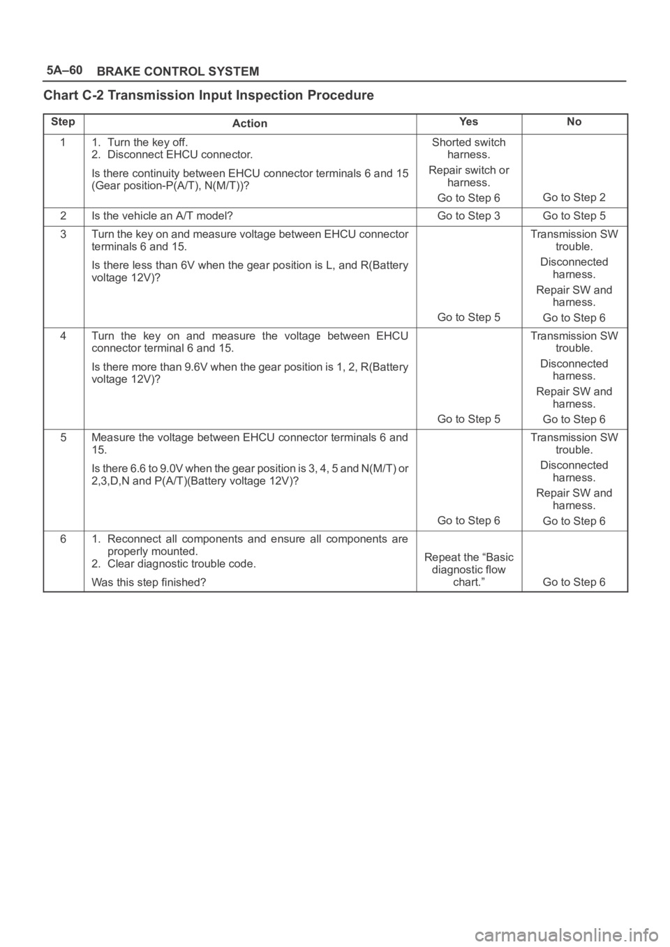
Chart C-2 Transmission Input Inspection Procedure
StepActionYe sNo
11. Turn the key off.
2. Disconnect EHCU connector.
Is there continuity between EHCU connector terminals 6 and 15
(Gear position-P(A/T), N(M/T))?Shorted switch
harness.
Repair switch or
harness.
Go to Step 6
Go to Step 2
2Is the vehicle an A/T model?Go to Step 3Go to Step 5
3Turn the key on and measure voltage between EHCU connector
terminals 6 and 15.
Is there less than 6V when the gear position is L, and R(Battery
voltage 12V)?
Go to Step 5
Transmission SW
trouble.
Disconnected
harness.
Repair SW and
harness.
Go to Step 6
4Turn the key on and measure the voltage between EHCU
connector terminal 6 and 15.
Is there more than 9.6V when the gear position is 1, 2, R(Battery
voltage 12V)?
Go to Step 5
Transmission SW
trouble.
Disconnected
harness.
Repair SW and
harness.
Go to Step 6
5Measure the voltage between EHCU connector terminals 6 and
15.
Is there 6.6 to 9.0V when the gear position is 3, 4, 5 and N(M/T) or
2,3,D,N and P(A/T)(Battery voltage 12V)?
Go to Step 6
Transmission SW
trouble.
Disconnected
harness.
Repair SW and
harness.
Go to Step 6
61. Reconnect all components and ensure all components are
properly mounted.
2. Clear diagnostic trouble code.
Was this step finished?
Repeat the “Basic
diagnostic flow
chart.”
Go to Step 6
Page 871 of 6000
5A–61 BRAKE CONTROL SYSTEM
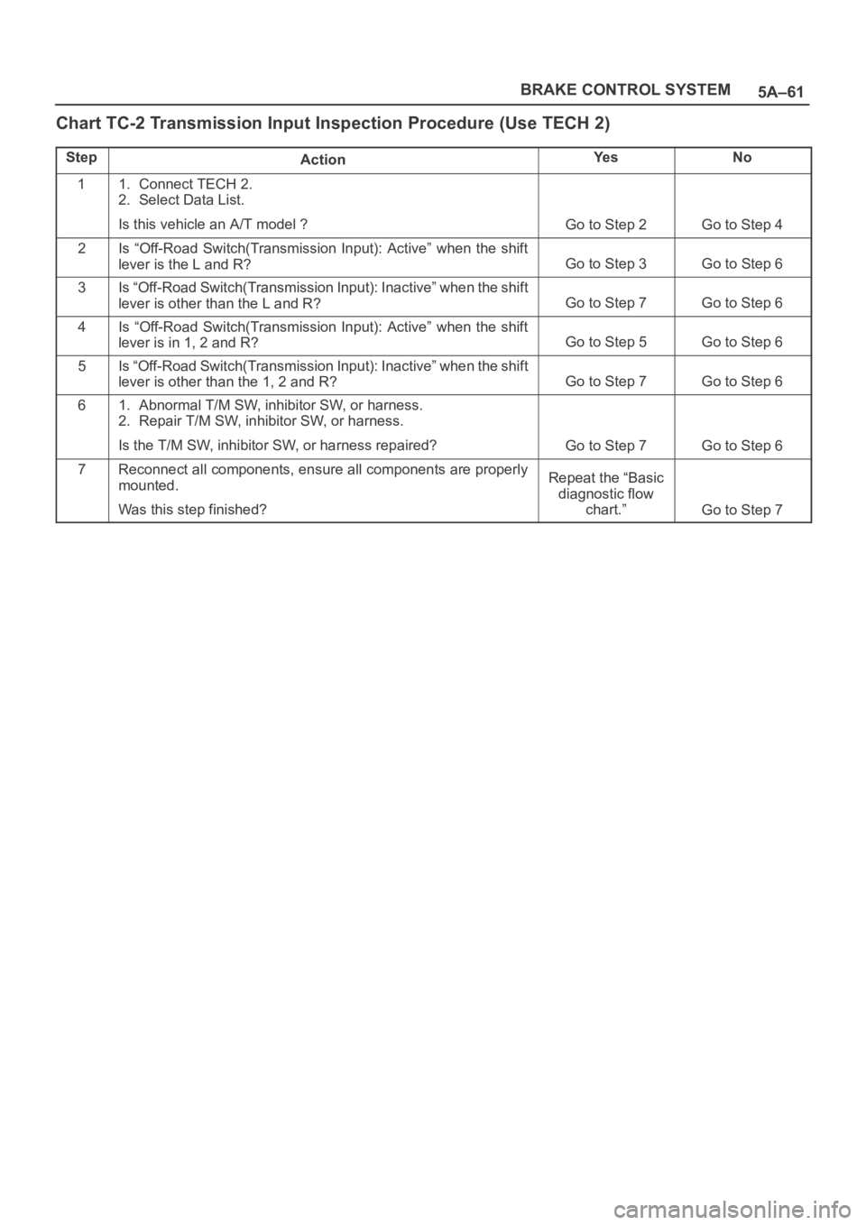
Chart TC-2 Transmission Input Inspection Procedure (Use TECH 2)
StepActionYe sNo
11. Connect TECH 2.
2. Select Data List.
Is this vehicle an A/T model ?
Go to Step 2Go to Step 4
2Is “Off-Road Switch(Transmission Input): Active” when the shift
lever is the L and R?
Go to Step 3Go to Step 6
3Is “Off-Road Switch(Transmission Input): Inactive” when the shift
lever is other than the L and R?
Go to Step 7Go to Step 6
4Is “Off-Road Switch(Transmission Input): Active” when the shift
lever is in 1, 2 and R?
Go to Step 5Go to Step 6
5Is “Off-Road Switch(Transmission Input): Inactive” when the shift
lever is other than the 1, 2 and R?
Go to Step 7Go to Step 6
61. Abnormal T/M SW, inhibitor SW, or harness.
2. Repair T/M SW, inhibitor SW, or harness.
Is the T/M SW, inhibitor SW, or harness repaired?
Go to Step 7Go to Step 6
7Reconnect all components, ensure all components are properly
mounted.
Was this step finished?Repeat the “Basic
diagnostic flow
chart.”
Go to Step 7
Page 1154 of 6000
6E–37 ENGINE DRIVEABILITY AND EMISSIONS
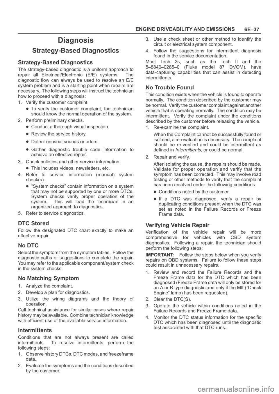
Diagnosis
Strategy-Based Diagnostics
Strategy-Based Diagnostics
The strategy-based diagnostic is a uniform approach to
repair all Electrical/Electronic (E/E) systems. The
diagnostic flow can always be used to resolve an E/E
system problem and is a starting point when repairs are
necessary. The following steps will instruct the technician
how to proceed with a diagnosis:
1. Verify the customer complaint.
To verify the customer complaint, the technician
should know the normal operation of the system.
2. Perform preliminary checks.
Conduct a thorough visual inspection.
Review the service history.
Detect unusual sounds or odors.
Gather diagnostic trouble code information to
achieve an effective repair.
3. Check bulletins and other service information.
This includes videos, newsletters, etc.
4. Refer to service information (manual) system
check(s).
“System checks” contain information on a system
that may not be supported by one or more DTCs.
System checks verify proper operation of the
system. This will lead the technician in an
organized approach to diagnostics.
5. Refer to service diagnostics.
DTC Stored
Follow the designated DTC chart exactly to make an
effective repair.
No DTC
Select the symptom from the symptom tables. Follow the
diagnostic paths or suggestions to complete the repair.
You may refer to the applicable component/system check
in the system checks.
No Matching Symptom
1. Analyze the complaint.
2. Develop a plan for diagnostics.
3. Utilize the wiring diagrams and the theory of
operation.
Call technical assistance for similar cases where repair
history may be available. Combine technician knowledge
with efficient use of the available service information.
Intermittents
Conditions that are not always present are called
intermittents. To resolve intermittents, perform the
following steps:
1. Observe history DTCs, DTC modes, and freezeframe
data.
2. Evaluate the symptoms and the conditions described
by the customer.3. Use a check sheet or other method to identify the
circuit or electrical system component.
4. Follow the suggestions for intermittent diagnosis
found in the service documentation.
Most Tech 2s, such as the Tech II and the
5–8840–0285–0 (Fluke model 87 DVOM), have
data-capturing capabilities that can assist in detecting
intermittents.
No Trouble Found
This condition exists when the vehicle is found to operate
normally. The condition described by the customer may
be normal. Verify the customer complaint against another
vehicle that is operating normally. The condition may be
intermittent. Verify the complaint under the conditions
described by the customer before releasing the vehicle.
1. Re-examine the complaint.
When the Complaint cannot be successfully found or
isolated, a re-evaluation is necessary. The complaint
should be re-verified and could be intermittent as
defined in
Intermittents, or could be normal.
2. Repair and verify.
After isolating the cause, the repairs should be made.
Validate for proper operation and verify that the
symptom has been corrected. This may involve road
testing or other methods to verify that the complaint
has been resolved under the following conditions:
Conditions noted by the customer.
If a DTC was diagnosed, verify a repair by
duplicating conditions present when the DTC was
set as noted in the Failure Records or Freeze
Frame data.
Verifying Vehicle Repair
Verification of the vehicle repair will be more
comprehensive for vehicles with OBD system
diagnostics. Following a repair, the technician should
perform the following steps:
IMPORTANT:Follow the steps below when you verify
repairs on OBD systems. Failure to follow these steps
could result in unnecessary repairs.
1. Review and record the Failure Records and the
Freeze Frame data for the DTC which has been
diagnosed (Freeze Frame data will only be stored for
an A or B type diagnostic and only if the MIL(”Check
Engine” lamp) has been requested).
2. Clear the DTC(S).
3. Operate the vehicle within conditions noted in the
Failure Records and Freeze Frame data.
4. Monitor the DTC status information for the specific
DTC which has been diagnosed until the diagnostic
test associated with that DTC runs.
Page 1162 of 6000
6E–45 ENGINE DRIVEABILITY AND EMISSIONS
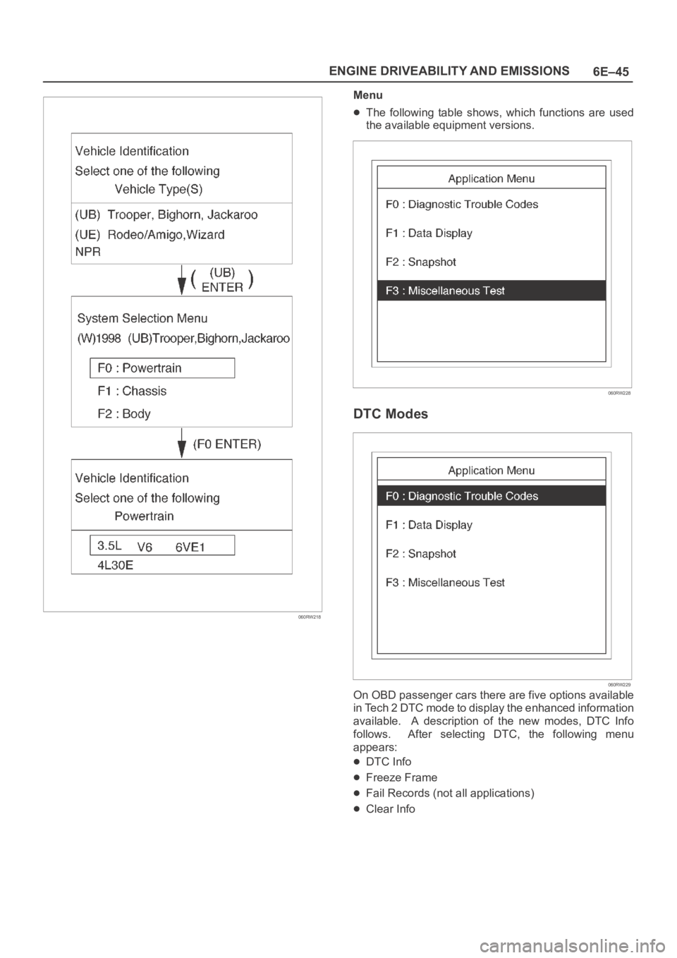
060RW218
Menu
The following table shows, which functions are used
the available equipment versions.
060RW228
DTC Modes
060RW229
On OBD passenger cars there are five options available
in Tech 2 DTC mode to display the enhanced information
available. A description of the new modes, DTC Info
follows. After selecting DTC, the following menu
appears:
DTC Info
Freeze Frame
Fail Records (not all applications)
Clear Info
Page 1185 of 6000
6E–68
ENGINE DRIVEABILITY AND EMISSIONS
Exhaust Gas Recirculation (EGR)
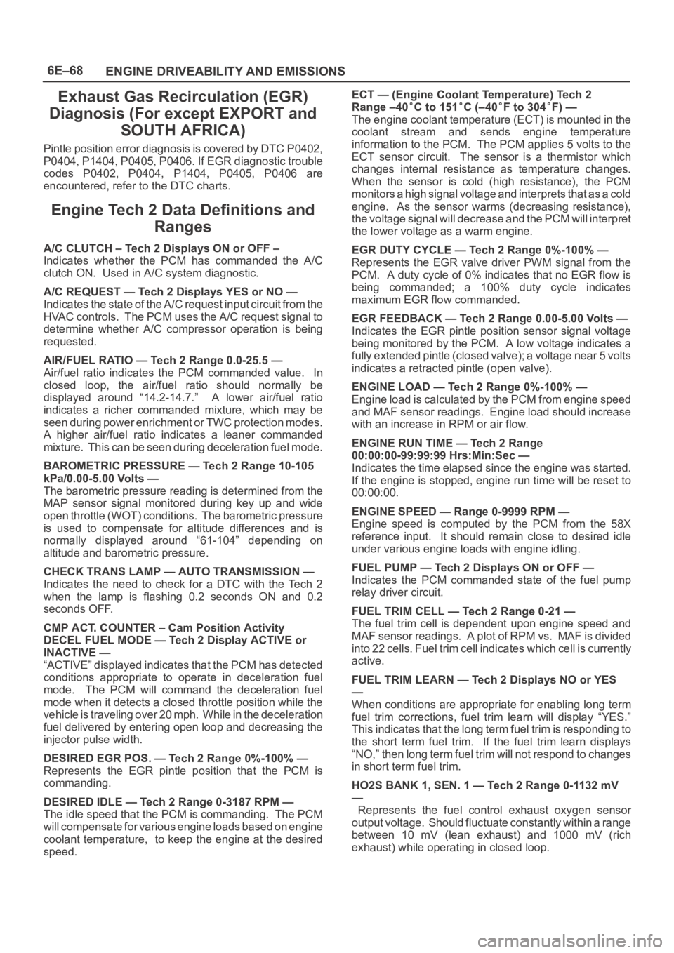
Diagnosis (For except EXPORT and
SOUTH AFRICA)
Pintle position error diagnosis is covered by DTC P0402,
P0404, P1404, P0405, P0406. If EGR diagnostic trouble
codes P0402, P0404, P1404, P0405, P0406 are
encountered, refer to the DTC charts.
Engine Tech 2 Data Definitions and
Ranges
A/C CLUTCH – Tech 2 Displays ON or OFF –
Indicates whether the PCM has commanded the A/C
clutch ON. Used in A/C system diagnostic.
A/C REQUEST — Tech 2 Displays YES or NO —
Indicates the state of the A/C request input circuit from the
HVAC controls. The PCM uses the A/C request signal to
determine whether A/C compressor operation is being
requested.
AIR/FUEL RATIO — Tech 2 Range 0.0-25.5 —
Air/fuel ratio indicates the PCM commanded value. In
closed loop, the air/fuel ratio should normally be
displayed around “14.2-14.7.” A lower air/fuel ratio
indicates a richer commanded mixture, which may be
seen during power enrichment or TWC protection modes.
A higher air/fuel ratio indicates a leaner commanded
mixture. This can be seen during deceleration fuel mode.
BAROMETRIC PRESSURE — Tech 2 Range 10-105
kPa/0.00-5.00 Volts —
The barometric pressure reading is determined from the
MAP sensor signal monitored during key up and wide
open throttle (WOT) conditions. The barometric pressure
is used to compensate for altitude differences and is
normally displayed around “61-104” depending on
altitude and barometric pressure.
CHECK TRANS LAMP — AUTO TRANSMISSION —
Indicates the need to check for a DTC with the Tech 2
when the lamp is flashing 0.2 seconds ON and 0.2
seconds OFF.
CMP ACT. COUNTER – Cam Position Activity
DECEL FUEL MODE — Tech 2 Display ACTIVE or
INACTIVE —
“ACTIVE” displayed indicates that the PCM has detected
conditions appropriate to operate in deceleration fuel
mode. The PCM will command the deceleration fuel
mode when it detects a closed throttle position while the
vehicle is traveling over 20 mph. While in the deceleration
fuel delivered by entering open loop and decreasing the
injector pulse width.
DESIRED EGR POS. — Tech 2 Range 0%-100% —
Represents the EGR pintle position that the PCM is
commanding.
DESIRED IDLE — Tech 2 Range 0-3187 RPM —
The idle speed that the PCM is commanding. The PCM
will compensate for various engine loads based on engine
coolant temperature, to keep the engine at the desired
speed.ECT — (Engine Coolant Temperature) Tech 2
Range –40
C to 151C (–40F to 304F) —
The engine coolant temperature (ECT) is mounted in the
coolant stream and sends engine temperature
information to the PCM. The PCM applies 5 volts to the
ECT sensor circuit. The sensor is a thermistor which
changes internal resistance as temperature changes.
When the sensor is cold (high resistance), the PCM
monitors a high signal voltage and interprets that as a cold
engine. As the sensor warms (decreasing resistance),
the voltage signal will decrease and the PCM will interpret
the lower voltage as a warm engine.
EGR DUTY CYCLE — Tech 2 Range 0%-100% —
Represents the EGR valve driver PWM signal from the
PCM. A duty cycle of 0% indicates that no EGR flow is
being commanded; a 100% duty cycle indicates
maximum EGR flow commanded.
EGR FEEDBACK — Tech 2 Range 0.00-5.00 Volts —
Indicates the EGR pintle position sensor signal voltage
being monitored by the PCM. A low voltage indicates a
fully extended pintle (closed valve); a voltage near 5 volts
indicates a retracted pintle (open valve).
ENGINE LOAD — Tech 2 Range 0%-100% —
Engine load is calculated by the PCM from engine speed
and MAF sensor readings. Engine load should increase
with an increase in RPM or air flow.
ENGINE RUN TIME — Tech 2 Range
00:00:00-99:99:99 Hrs:Min:Sec —
Indicates the time elapsed since the engine was started.
If the engine is stopped, engine run time will be reset to
00:00:00.
ENGINE SPEED — Range 0-9999 RPM —
Engine speed is computed by the PCM from the 58X
reference input. It should remain close to desired idle
under various engine loads with engine idling.
FUEL PUMP — Tech 2 Displays ON or OFF —
Indicates the PCM commanded state of the fuel pump
relay driver circuit.
FUEL TRIM CELL — Tech 2 Range 0-21 —
The fuel trim cell is dependent upon engine speed and
MAF sensor readings. A plot of RPM vs. MAF is divided
into 22 cells. Fuel trim cell indicates which cell is currently
active.
FUEL TRIM LEARN — Tech 2 Displays NO or YES
—
When conditions are appropriate for enabling long term
fuel trim corrections, fuel trim learn will display “YES.”
This indicates that the long term fuel trim is responding to
the short term fuel trim. If the fuel trim learn displays
“NO,” then long term fuel trim will not respond to changes
in short term fuel trim.
HO2S BANK 1, SEN. 1 — Tech 2 Range 0-1132 mV
—
Represents the fuel control exhaust oxygen sensor
output voltage. Should fluctuate constantly within a range
between 10 mV (lean exhaust) and 1000 mV (rich
exhaust) while operating in closed loop.
Page 1186 of 6000
6E–69 ENGINE DRIVEABILITY AND EMISSIONS
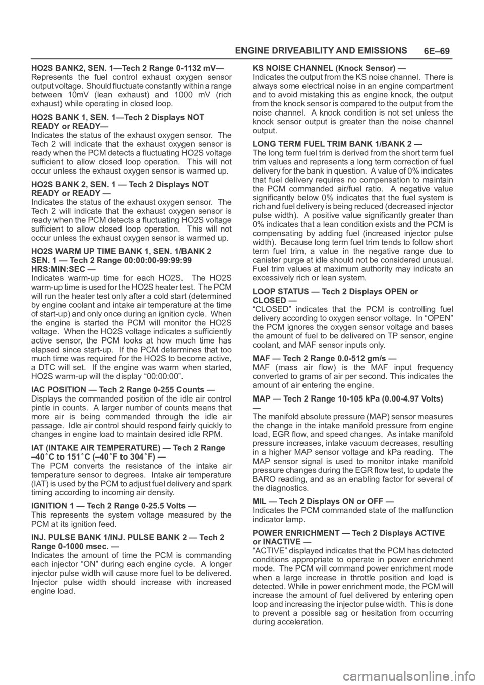
HO2S BANK2, SEN. 1—Tech 2 Range 0-1132 mV—
Represents the fuel control exhaust oxygen sensor
output voltage. Should fluctuate constantly within a range
between 10mV (lean exhaust) and 1000 mV (rich
exhaust) while operating in closed loop.
HO2S BANK 1, SEN. 1—Tech 2 Displays NOT
READY or READY—
Indicates the status of the exhaust oxygen sensor. The
Tech 2 will indicate that the exhaust oxygen sensor is
ready when the PCM detects a fluctuating HO2S voltage
sufficient to allow closed loop operation. This will not
occur unless the exhaust oxygen sensor is warmed up.
HO2S BANK 2, SEN. 1 — Tech 2 Displays NOT
READY or READY —
Indicates the status of the exhaust oxygen sensor. The
Tech 2 will indicate that the exhaust oxygen sensor is
ready when the PCM detects a fluctuating HO2S voltage
sufficient to allow closed loop operation. This will not
occur unless the exhaust oxygen sensor is warmed up.
HO2S WARM UP TIME BANK 1, SEN. 1/BANK 2
SEN. 1 — Tech 2 Range 00:00:00-99:99:99
HRS:MIN:SEC —
Indicates warm-up time for each HO2S. The HO2S
warm-up time is used for the HO2S heater test. The PCM
will run the heater test only after a cold start (determined
by engine coolant and intake air temperature at the time
of start-up) and only once during an ignition cycle. When
the engine is started the PCM will monitor the HO2S
voltage. When the HO2S voltage indicates a sufficiently
active sensor, the PCM looks at how much time has
elapsed since start-up. If the PCM determines that too
much time was required for the HO2S to become active,
a DTC will set. If the engine was warm when started,
HO2S warm-up will the display “00:00:00”.
IAC POSITION — Tech 2 Range 0-255 Counts —
Displays the commanded position of the idle air control
pintle in counts. A larger number of counts means that
more air is being commanded through the idle air
passage. Idle air control should respond fairly quickly to
changes in engine load to maintain desired idle RPM.
IAT (INTAKE AIR TEMPERATURE) — Tech 2 Range
–40
C to 151C (–40F to 304F) —
The PCM converts the resistance of the intake air
temperature sensor to degrees. Intake air temperature
(IAT) is used by the PCM to adjust fuel delivery and spark
timing according to incoming air density.
IGNITION 1 — Tech 2 Range 0-25.5 Volts —
This represents the system voltage measured by the
PCM at its ignition feed.
INJ. PULSE BANK 1/INJ. PULSE BANK 2 — Tech 2
Range 0-1000 msec. —
Indicates the amount of time the PCM is commanding
each injector “ON” during each engine cycle. A longer
injector pulse width will cause more fuel to be delivered.
Injector pulse width should increase with increased
engine load.KS NOISE CHANNEL (Knock Sensor) —
Indicates the output from the KS noise channel. There is
always some electrical noise in an engine compartment
and to avoid mistaking this as engine knock, the output
from the knock sensor is compared to the output from the
noise channel. A knock condition is not set unless the
knock sensor output is greater than the noise channel
output.
LONG TERM FUEL TRIM BANK 1/BANK 2 —
The long term fuel trim is derived from the short term fuel
trim values and represents a long term correction of fuel
delivery for the bank in question. A value of 0% indicates
that fuel delivery requires no compensation to maintain
the PCM commanded air/fuel ratio. A negative value
significantly below 0% indicates that the fuel system is
rich and fuel delivery is being reduced (decreased injector
pulse width). A positive value significantly greater than
0% indicates that a lean condition exists and the PCM is
compensating by adding fuel (increased injector pulse
width). Because long term fuel trim tends to follow short
term fuel trim, a value in the negative range due to
canister purge at idle should not be considered unusual.
Fuel trim values at maximum authority may indicate an
excessively rich or lean system.
LOOP STATUS — Tech 2 Displays OPEN or
CLOSED —
“CLOSED” indicates that the PCM is controlling fuel
delivery according to oxygen sensor voltage. In “OPEN”
the PCM ignores the oxygen sensor voltage and bases
the amount of fuel to be delivered on TP sensor, engine
coolant, and MAF sensor inputs only.
MAF — Tech 2 Range 0.0-512 gm/s —
MAF (mass air flow) is the MAF input frequency
converted to grams of air per second. This indicates the
amount of air entering the engine.
MAP — Tech 2 Range 10-105 kPa (0.00-4.97 Volts)
—
The manifold absolute pressure (MAP) sensor measures
the change in the intake manifold pressure from engine
load, EGR flow, and speed changes. As intake manifold
pressure increases, intake vacuum decreases, resulting
in a higher MAP sensor voltage and kPa reading. The
MAP sensor signal is used to monitor intake manifold
pressure changes during the EGR flow test, to update the
BARO reading, and as an enabling factor for several of
the diagnostics.
MIL — Tech 2 Displays ON or OFF —
Indicates the PCM commanded state of the malfunction
indicator lamp.
POWER ENRICHMENT — Tech 2 Displays ACTIVE
or INACTIVE —
“ACTIVE” displayed indicates that the PCM has detected
conditions appropriate to operate in power enrichment
mode. The PCM will command power enrichment mode
when a large increase in throttle position and load is
detected. While in power enrichment mode, the PCM will
increase the amount of fuel delivered by entering open
loop and increasing the injector pulse width. This is done
to prevent a possible sag or hesitation from occurring
during acceleration.
Page 1188 of 6000
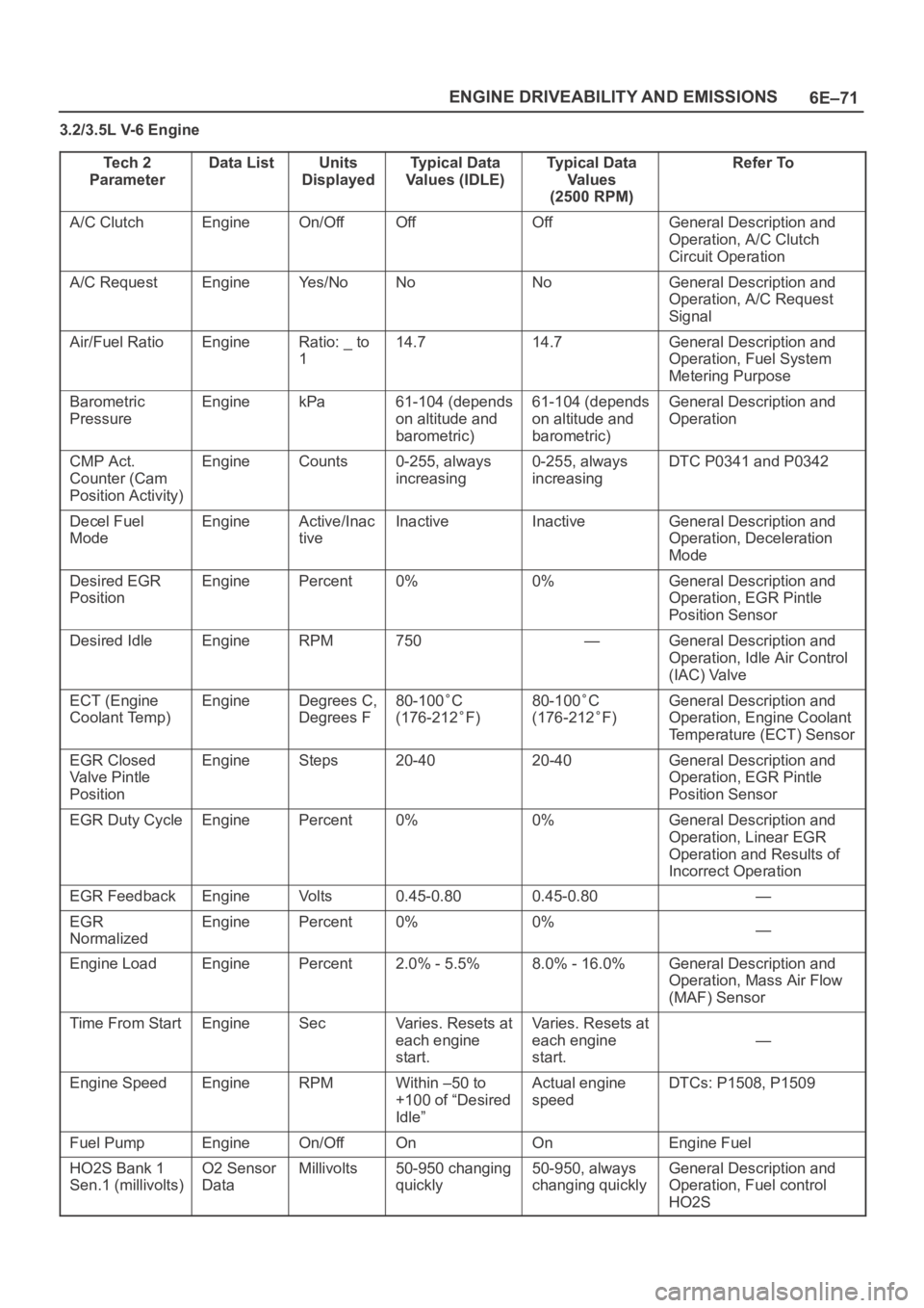
6E–71 ENGINE DRIVEABILITY AND EMISSIONS
3.2/3.5L V-6 Engine
Te c h 2
Parameter
Data ListUnits
DisplayedTypical Data
Values (IDLE)Typical Data
Va l u e s
(2500 RPM)Refer To
A/C ClutchEngineOn/OffOffOffGeneral Description and
Operation, A/C Clutch
Circuit Operation
A/C RequestEngineYe s / N oNoNoGeneral Description and
Operation, A/C Request
Signal
Air/Fuel RatioEngineRatio: _ to
114.714.7General Description and
Operation, Fuel System
Metering Purpose
Barometric
PressureEnginekPa61-104 (depends
on altitude and
barometric)61-104 (depends
on altitude and
barometric)General Description and
Operation
CMP Act.
Counter (Cam
Position Activity)EngineCounts0-255, always
increasing0-255, always
increasingDTC P0341 and P0342
Decel Fuel
ModeEngineActive/Inac
tiveInactiveInactiveGeneral Description and
Operation, Deceleration
Mode
Desired EGR
PositionEnginePercent0%0%General Description and
Operation, EGR Pintle
Position Sensor
Desired IdleEngineRPM750—General Description and
Operation, Idle Air Control
(IAC) Valve
ECT (Engine
Coolant Temp)EngineDegrees C,
Degrees F80-100C
(176-212
F)
80-100C
(176-212
F)
General Description and
Operation, Engine Coolant
Temperature (ECT) Sensor
EGR Closed
Valve Pintle
PositionEngineSteps20-4020-40General Description and
Operation, EGR Pintle
Position Sensor
EGR Duty CycleEnginePercent0%0%General Description and
Operation, Linear EGR
Operation and Results of
Incorrect Operation
EGR FeedbackEngineVo l t s0.45-0.800.45-0.80—
EGR
NormalizedEnginePercent0%0%—
Engine LoadEnginePercent2.0% - 5.5%8.0% - 16.0%General Description and
Operation, Mass Air Flow
(MAF) Sensor
Time From StartEngineSecVaries. Resets at
each engine
start.Varies. Resets at
each engine
start.
—
Engine SpeedEngineRPMWithin –50 to
+100 of “Desired
Idle”Actual engine
speedDTCs: P1508, P1509
Fuel PumpEngineOn/OffOnOnEngine Fuel
HO2S Bank 1
Sen.1 (millivolts)O2 Sensor
DataMillivolts50-950 changing
quickly50-950, always
changing quicklyGeneral Description and
Operation, Fuel control
HO2S