1998 OPEL FRONTERA ECO mode
[x] Cancel search: ECO modePage 625 of 6000

DRIVE LINE CONTROL SYSTEM (TOD) 4B2–54
Check flowTrouble codePhenomenonStandard
1333The ADC line is short-circuited to
GND.—
NOTE:
The on/off signal line of the shift on the fly system is
short–circuited to GND.
The system enters into the fail-safe mode because of
fusing or system protection.
(If a short–circuit is observed on GND, the output to
the on/off signal line becomes 0V.)
D04RW059
Page 648 of 6000

4B2–77 DRIVE LINE CONTROL SYSTEM (TOD)
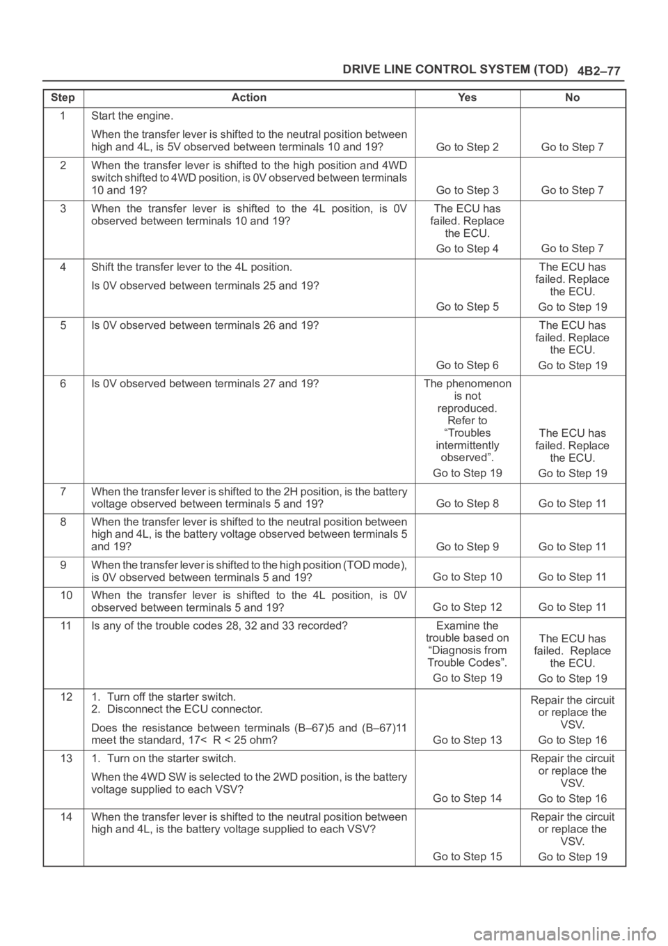
StepActionYe sNo
1Start the engine.
When the transfer lever is shifted to the neutral position between
high and 4L, is 5V observed between terminals 10 and 19?
Go to Step 2Go to Step 7
2When the transfer lever is shifted to the high position and 4WD
switch shifted to 4WD position, is 0V observed between terminals
10 and 19?
Go to Step 3Go to Step 7
3When the transfer lever is shifted to the 4L position, is 0V
observed between terminals 10 and 19?The ECU has
failed. Replace
the ECU.
Go to Step 4
Go to Step 7
4Shift the transfer lever to the 4L position.
Is 0V observed between terminals 25 and 19?
Go to Step 5
The ECU has
failed. Replace
the ECU.
Go to Step 19
5Is 0V observed between terminals 26 and 19?
Go to Step 6
The ECU has
failed. Replace
the ECU.
Go to Step 19
6Is 0V observed between terminals 27 and 19?The phenomenon
is not
reproduced.
Refer to
“Troubles
intermittently
observed”.
Go to Step 19
The ECU has
failed. Replace
the ECU.
Go to Step 19
7When the transfer lever is shifted to the 2H position, is the battery
voltage observed between terminals 5 and 19?
Go to Step 8Go to Step 11
8When the transfer lever is shifted to the neutral position between
high and 4L, is the battery voltage observed between terminals 5
and 19?
Go to Step 9Go to Step 11
9When the transfer lever is shifted to the high position (TOD mode),
is 0V observed between terminals 5 and 19?
Go to Step 10Go to Step 11
10When the transfer lever is shifted to the 4L position, is 0V
observed between terminals 5 and 19?
Go to Step 12Go to Step 11
11Is any of the trouble codes 28, 32 and 33 recorded?Examine the
trouble based on
“Diagnosis from
Trouble Codes”.
Go to Step 19
The ECU has
failed. Replace
the ECU.
Go to Step 19
121. Turn off the starter switch.
2. Disconnect the ECU connector.
Does the resistance between terminals (B–67)5 and (B–67)11
meet the standard, 17< R < 25 ohm?
Go to Step 13
Repair the circuit
or replace the
VSV.
Go to Step 16
131. Turn on the starter switch.
When the 4WD SW is selected to the 2WD position, is the battery
voltage supplied to each VSV?
Go to Step 14
Repair the circuit
or replace the
VSV.
Go to Step 16
14When the transfer lever is shifted to the neutral position between
high and 4L, is the battery voltage supplied to each VSV?
Go to Step 15
Repair the circuit
or replace the
VSV.
Go to Step 19
Page 657 of 6000

DRIVE LINE CONTROL SYSTEM (TOD) 4B2–86
Diagnosis from Symptom
Troubles that are not indicated by the warning lamp are
listed in the table below. These troubles are caused by
the faults that cannot be detected by the self-diagnostic
function of the control unit.
If this type of trouble is observed, interview the customer
and conduct test runs to reproduce the trouble,cross-check the reported trouble with the listed
phenomena, and diagnose and analyze the trouble on the
item by item basis.
PhenomenaMajor causeCorrective action
1The tight corner braking is ob-
served when the vehicle is subject
to full steering.The standard tires are not used.
The tire pressure is incorrect.
The tires are worn inuniformity.
The transfer or wiring is
imperfect.
The limited slip differential is
failed.
Check and recondition the ve-
hicle according to Chart 1.
2Even if the 4WD SW is select to the
4WD position, the 4WD mode is not
active, resulting in remarkable rear
wheel spin.The transfer or wiring is
imperfect.
The shift on the fly system is
failed.
Check and recondition the ve-
hicle according to Chart 2.
3When the 4WD SW is select to
the 4WD position, the drive
resistance of the 4WD system is
too large to get sufficient running
speed.
Noised drive line.
The standard tires are not used.
The tire pressure is incorrect.
The tires are worn inuniformity.
The transfer or wiring is
imperfect.
The limited slip differential is
Check and recondition the ve-
hicle according to Chart 1.
4The shift on the fly system (front
axle) generates gear noises.The wiring is imperfect.
The full automatic free wheel
hub is failed.
Check and recondition the ve-
hicle according to Chart 3.
5The braking distance gets long
even when the ABS is active.The wiring is imperfect.
The ABS is failed.
Check and recondition the ve-
hicle according to Chart 4.
Page 663 of 6000

DRIVE LINE CONTROL SYSTEM (TOD) 4B2–92
Chart 3The shift on the fly system generates gear noises.
(The fuel economy is bad in the 2H mode.)
Function of circuit—
Fail conditionWhen the vehicle is run in the 2H mode, the shift on the fly system generates gear
noises or the front wheel gears are engaged to generate a shock.
D04RW055
Page 728 of 6000

TRANSFER CASE (STANDARD TYPE)
4D1–7
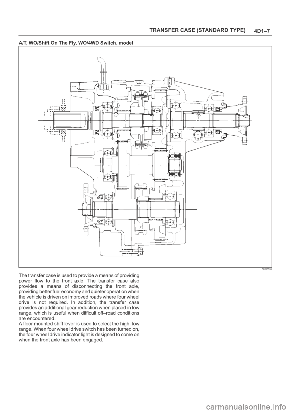
A/T, WO/Shift On The Fly, WO/4WD Switch, model
A07RW055
The transfer case is used to provide a means of providing
power flow to the front axle. The transfer case also
provides a means of disconnecting the front axle,
providing better fuel economy and quieter operation when
the vehicle is driven on improved roads where four wheel
drive is not required. In addition, the transfer case
provides an additional gear reduction when placed in low
range, which is useful when difficult off–road conditions
are encountered.
A floor mounted shift lever is used to select the high–low
range. When four wheel drive switch has been turned on,
the four wheel drive indicator light is designed to come on
when the front axle has been engaged.
Page 734 of 6000

TRANSFER CASE (STANDARD TYPE)
4D1–13
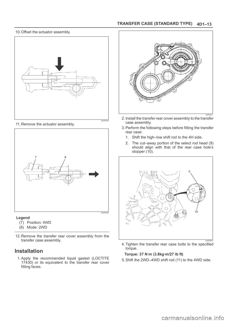
10. Offset the actuator assembly.
220RW028
11. Remove the actuator assembly.
220RW029
Legend
(7) Position: 4WD
(8) Mode: 2WD
12. Remove the transfer rear cover assembly from the
transfer case assembly.
Installation
1. Apply the recommended liquid gasket (LOCTITE
17430) or its equivalent to the transfer rear cover
fitting faces.
220RS017
2. Install the transfer rear cover assembly to the transfer
case assembly.
3. Perform the following steps before fitting the transfer
rear case:
1. Shift the high–low shift rod to the 4H side.
2. The cut–away portion of the select rod head (9)
should align with that of the rear case hole’s
stopper (10).
230RW004
4. Tighten the transfer rear case bolts to the specified
torque.
Torque: 37 Nꞏm (3.8kgꞏm/27 lb ft)
5. Shift the 2WD–4WD shift rod (11) to the 4WD side.
Page 816 of 6000

5A–6
BRAKE CONTROL SYSTEM
Test Driving ABS Complaint Vehicles
In case that there has been an malfunction in the lighting
pattern of “ABS” warning light, the fault can be located in
accordance with the “DIAGNOSIS BY “ABS” WARNING
LIGHT ILLUMINATION PATTERN” . In case of such
trouble as can be detected by the driver as a vehicle
symptom, however, it is necessary to give a test drive
following the test procedure mentioned below, thereby
reproducing the symptom for trouble diagnosis on a
symptom basis:
1. Start the engine and make sure that the “ABS” W/L
goes OFF. If the W/L remains ON, it means that the
Diagnostic Trouble Code (DTC) is stored. Therefore,
read the code and locate the fault.
2. Start the vehicle and accelerate to about 30 km/h (19
mph) or more.
3. Slowly brake and stop the vehicle completely.
4. Then restart the vehicle and accelerate to about 40
km/h (25 mph) or more.
5. Brake at a time so as to actuate the ABS and stop the
vehicle.
6. Be cautious of abnormality during the test. If the W/L
is actuated while driving, read the DTC and locate the
fault.
7. If the abnormality is not reproduced by the test, make
best efforts to reproduce the situation reported by the
customer.
8. If the abnormality has been detected, repair in
accordance with the “SYMPTOM DIAGNOSIS” .NOTE:Be sure to give a test drive on a wide, even road with
little traffic.
If an abnormality is detected, be sure to suspend the
test and start trouble diagnosis at once.
“ABS” Warning Light
When ABS trouble occurs and actuates when possible
the “ABS” warning light, the trouble code corresponding
to the trouble is stored in the EHCU. Only the ordinary
brake system is available when the ABS is turned off.
When the “ABS” warning light is actuated, if the starter
switch is set ON after setting it OFF once, the EHCU
checks up on the entire system and, if there is no
abnormality, judges ABS to work currently and the
warning light works normally even though the trouble
code is stored.
NOTE: Illumination of the “ABS” warning light indicates
that anti-lock braking is no longer available. Power
assisted braking without anti-lock control is still available.
Normal Operation
“ABS” Warning Light
W h e n t h e i g n i t i o n i s f i r s t m o v e d f r o m “ O F F ” t o “ R U N ” , t h e
amber “ABS” warning light will turn “ON” . The “ABS”
warning light will turn “ON” during engine starting and will
usually stay “ON” for approximately three seconds after
the ignition switch is returned to the “ON” position. The
warning light should remain “OFF” at all other times.
Basic Diagnostic Flow Chart
StepActionYe sNo
11. Customer complaint.
2. Questioning to customer.
3. Basic inspection (Refer to “Basic inspection procedure”)
Using TECH 2?
Go to Step 2Go to Step 4
2Make sure of DTC by mode “F0: Diagnostic Trouble Codes”.
Is EHCU including DTC?
Go to Step 3Go to Step 5
31. Repair of faulty part.
2. Elimination of DTC.
3. Inspection of “ABS” W/L Illumination pattern with ignition SW
“ON”.
4. Test drive.
Does repeat trouble?
Repeat the
diagnosis it the
symptom or DTC
appears again Go
to Step 1
Go to Step 5
4Check if the DTC is stored.
Is EHCU including DTC?
Go to Step 3
Trouble diagnosis
based on
symptom (Refer
to “SYMPTOM
DIAGNOSIS”) Go
to Step 3
51. Reconnect all components and ensure all component are
properly mounted.
2. Clear diagnostic trouble code.
Was this step finished?
FinishedGo to Step 5
Page 846 of 6000

5A–36
BRAKE CONTROL SYSTEM
StepNo Ye s
Action
10Is the input of 4WD controller normal?
Go to Step 11
Replace
controller or
repair harness.
Go to Step 11
11Reconnect all components and ensure all components are
properly mounted.
Was this step finished?Repeat the “Basic
diagnostic flow
chart.”
Go to Step 11
Chart TA-1 ABS Works Frequently But Vehicle Does Not Decelerate (Use TECH 2)
StepActionYe sNo
11. Connect TECH 2.
2. Make sure of the output conditions of each wheel speed
sensor by mode “F1: Data Display”.
Is the output of each sensor normal?
Go to Step 2
Replace wheel
speed sensor.
Go to Step 3
2Return to Chart A-1.
Was the Chart A-1 finished?
Go to Step 3Go to Step 2
3Reconnect all components, ensure all components are properly
mounted.
Was this step finished?Repeat the “Basic
diagnostic flow
chart.”
Go to Step 3
Chart A-2 Uneven Braking Occurs While ABS Works
StepActionYe sNo
1Is there play in each sensor?Repair.
Go to Step 5
Go to Step 2
2Is there damage or powdered iron sticking to each sensor/sensor
ring?Repair.
Go to Step 5
Go to Step 3
3Is the output of each sensor normal? (Refer to chart C-1 or TC-1)
Go to Step 4
Replace sensor
or repair harness.
Go to Step 5
4Is brake pipe connecting order correct?
Replace EHCU.
Go to Step 5
Reconnect brake
pipe correctly.
Go to Step 5
5Reconnect all components, ensure all components are properly
mounted.
Was this step finished?Repeat the “Basic
diagnostic flow
chart.”
Go to Step 5
Chart A-3, TA-3 The Wheels Are Locked
StepActionYe sNo
1Is ABS working?Go to Step 2Go to Step 6
2Is vehicle speed under 10 km/h (6mph)?Normal.Go to Step 3
3Is sensor output normal? (Chart C-1 or TC-1)
Go to Step 4
Replace sensor
or repair harness.
Go to Step 9
4Is transmission input normal? (Chart C-2 or TC-2)
Go to Step 5
Replace SW or
repair harness.
Go to Step 9