1998 OPEL FRONTERA wheel
[x] Cancel search: wheelPage 4053 of 6000
4B1–8
DRIVE LINE CONTROL SYSTEM (SHIFT ON THE FLY)
Normal Operation
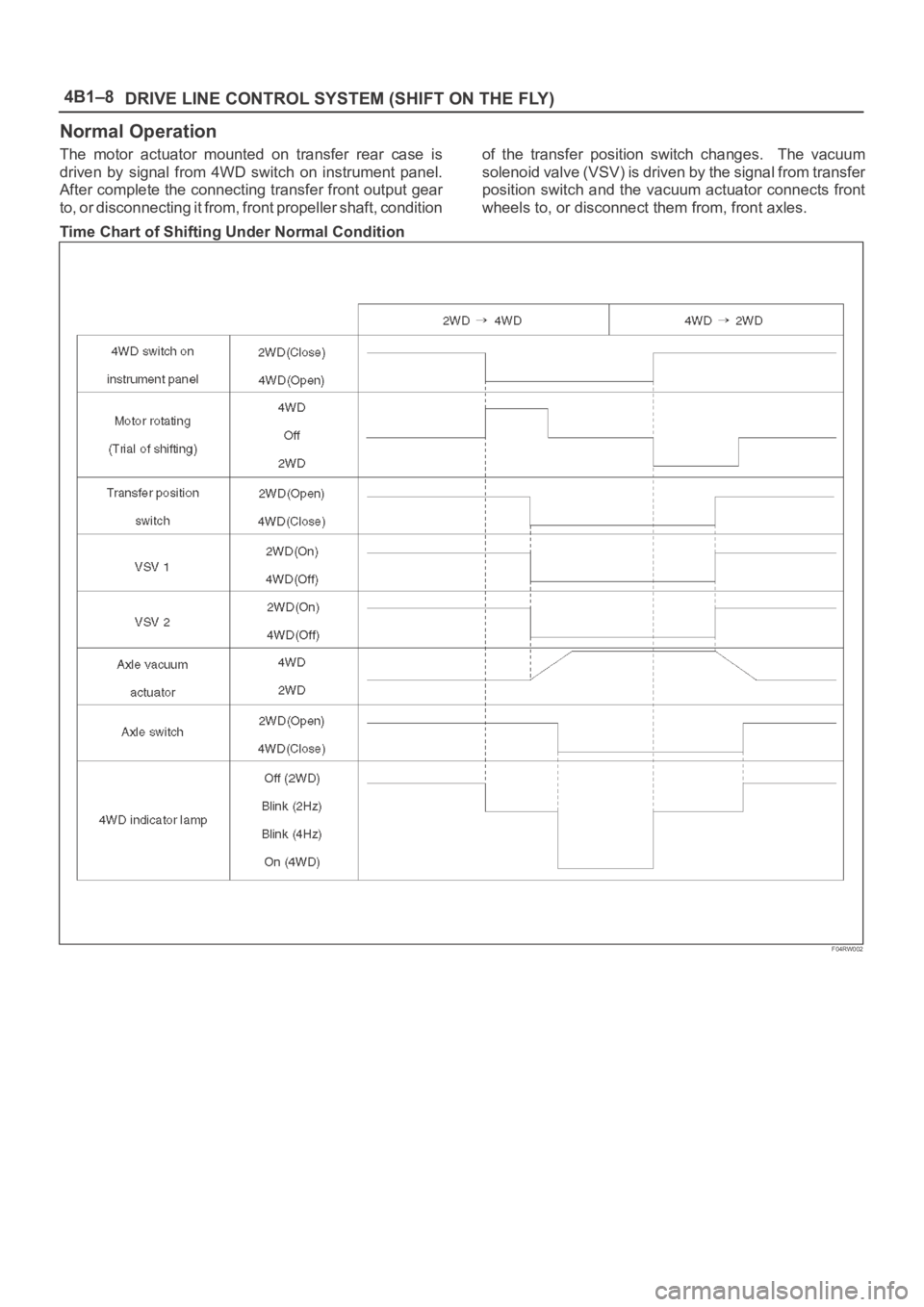
The motor actuator mounted on transfer rear case is
driven by signal from 4WD switch on instrument panel.
After complete the connecting transfer front output gear
to, or disconnecting it from, front propeller shaft, conditionof the transfer position switch changes. The vacuum
solenoid valve (VSV) is driven by the signal from transfer
position switch and the vacuum actuator connects front
wheels to, or disconnect them from, front axles.
Time Chart of Shifting Under Normal Condition
F04RW002
Page 4056 of 6000
4B1–11 DRIVE LINE CONTROL SYSTEM (SHIFT ON THE FLY)
Functions of Indicator Lamp
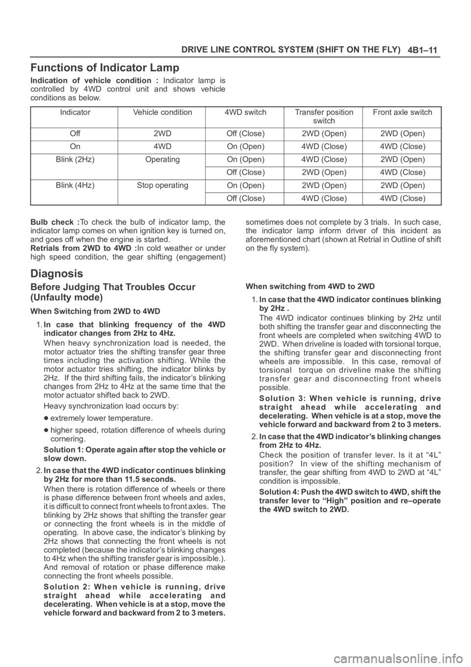
Indication of vehicle condition : Indicator lamp is
controlled by 4WD control unit and shows vehicle
conditions as below.
Indicator
Vehicle condition4WD switchTransfer position
switchFront axle switch
Off2WDOff (Close)2WD (Open)2WD (Open)
On4WDOn (Open)4WD (Close)4WD (Close)
Blink (2Hz)OperatingOn (Open)4WD (Close)2WD (Open)
Off (Close)2WD (Open)4WD (Close)
Blink (4Hz)Stop operatingOn (Open)2WD (Open)2WD (Open)
Off (Close)4WD (Close)4WD (Close)
Bulb check :To check the bulb of indicator lamp, the
indicator lamp comes on when ignition key is turned on,
and goes off when the engine is started.
Retrials from 2WD to 4WD :In cold weather or under
high speed condition, the gear shifting (engagement)sometimes does not complete by 3 trials. In such case,
the indicator lamp inform driver of this incident as
aforementioned chart (shown at Retrial in Outline of shift
on the fly system).
Diagnosis
Before Judging That Troubles Occur
(Unfaulty mode)
When Switching from 2WD to 4WD
1.In case that blinking frequency of the 4WD
indicator changes from 2Hz to 4Hz.
When heavy synchronization load is needed, the
motor actuator tries the shifting transfer gear three
times including the activation shifting. While the
motor actuator tries shifting, the indicator blinks by
2Hz. If the third shifting fails, the indicator’s blinking
changes from 2Hz to 4Hz at the same time that the
motor actuator shifted back to 2WD.
Heavy synchronization load occurs by:
extremely lower temperature.
higher speed, rotation difference of wheels during
cornering.
Solution 1: Operate again after stop the vehicle or
slow down.
2.In case that the 4WD indicator continues blinking
by 2Hz for more than 11.5 seconds.
When there is rotation difference of wheels or there
is phase difference between front wheels and axles,
it is difficult to connect front wheels to front axles. The
blinking by 2Hz shows that shifting the transfer gear
or connecting the front wheels is in the middle of
operating. In above case, the indicator’s blinking by
2Hz shows that connecting the front wheels is not
completed (because the indicator’s blinking changes
to 4Hz when the shifting transfer gear is impossible.).
And removal of rotation or phase difference make
connecting the front wheels possible.
Solution 2: When vehicle is running, drive
straight ahead while accelerating and
decelerating. When vehicle is at a stop, move the
vehicle forward and backward from 2 to 3 meters.When switching from 4WD to 2WD
1.In case that the 4WD indicator continues blinking
by 2Hz .
The 4WD indicator continues blinking by 2Hz until
both shifting the transfer gear and disconnecting the
front wheels are completed when switching 4WD to
2WD. When driveline is loaded with torsional torque,
the shifting transfer gear and disconnecting front
wheels are impossible. In this case, removal of
torsional torque on driveline make the shifting
transfer gear and disconnecting front wheels
possible.
Solution 3: When vehicle is running, drive
straight ahead while accelerating and
decelerating. When vehicle is at a stop, move the
vehicle forward and backward from 2 to 3 meters.
2.In case that the 4WD indicator’s blinking changes
from 2Hz to 4Hz.
Check the position of transfer lever. Is it at “4L”
position? In view of the shifting mechanism of
transfer, the gear shifting from 4WD to 2WD at “4L”
condition is impossible.
Solution 4: Push the 4WD switch to 4WD, shift the
transfer lever to “High” position and re–operate
the 4WD switch to 2WD.
Page 4075 of 6000
4B1–30
DRIVE LINE CONTROL SYSTEM (SHIFT ON THE FLY)
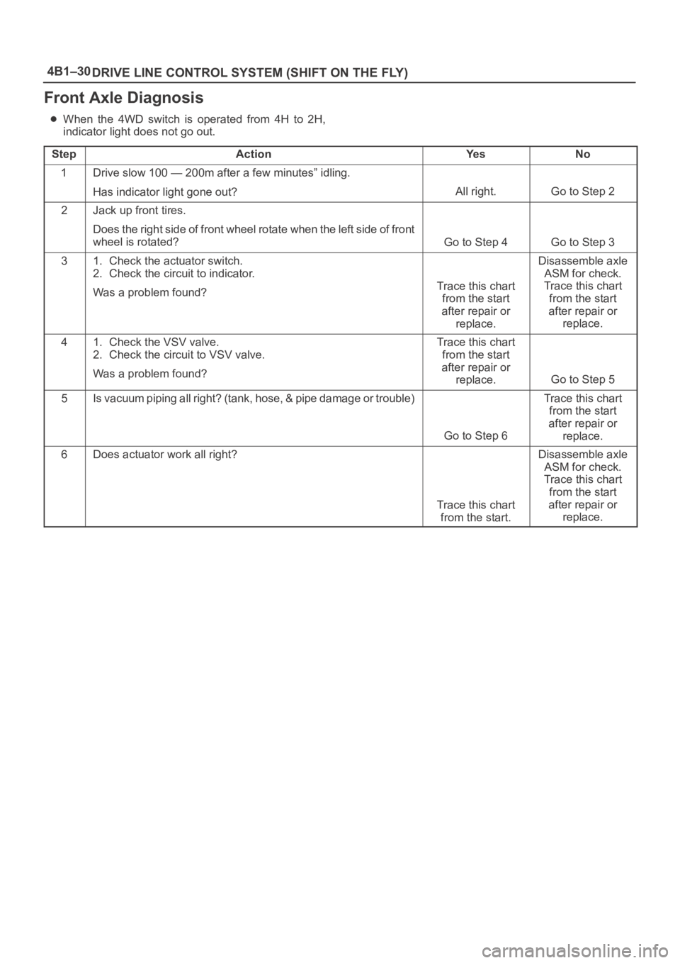
Front Axle Diagnosis
When the 4WD switch is operated from 4H to 2H,
indicator light does not go out.
Step
ActionYe sNo
1Drive slow 100 — 200m after a few minutes” idling.
Has indicator light gone out?
All right.Go to Step 2
2Jack up front tires.
Does the right side of front wheel rotate when the left side of f r o n t
wheel is rotated?
Go to Step 4Go to Step 3
31. Check the actuator switch.
2. Check the circuit to indicator.
Was a problem found?
Trace this chart
from the start
after repair or
replace.
Disassemble axle
ASM for check.
Trace this chart
from the start
after repair or
replace.
41. Check the VSV valve.
2. Check the circuit to VSV valve.
Was a problem found?Trace this chart
from the start
after repair or
replace.
Go to Step 5
5I s v a c u u m p i p i n g a l l r i g h t ? ( t a n k , h o s e , & p i p e d a m a g e o r t r o u ble)
Go to Step 6
Trace this chart
from the start
after repair or
replace.
6Does actuator work all right?
Trace this chart
from the start.
Disassemble axle
ASM for check.
Trace this chart
from the start
after repair or
replace.
Page 4076 of 6000
4B1–31 DRIVE LINE CONTROL SYSTEM (SHIFT ON THE FLY)
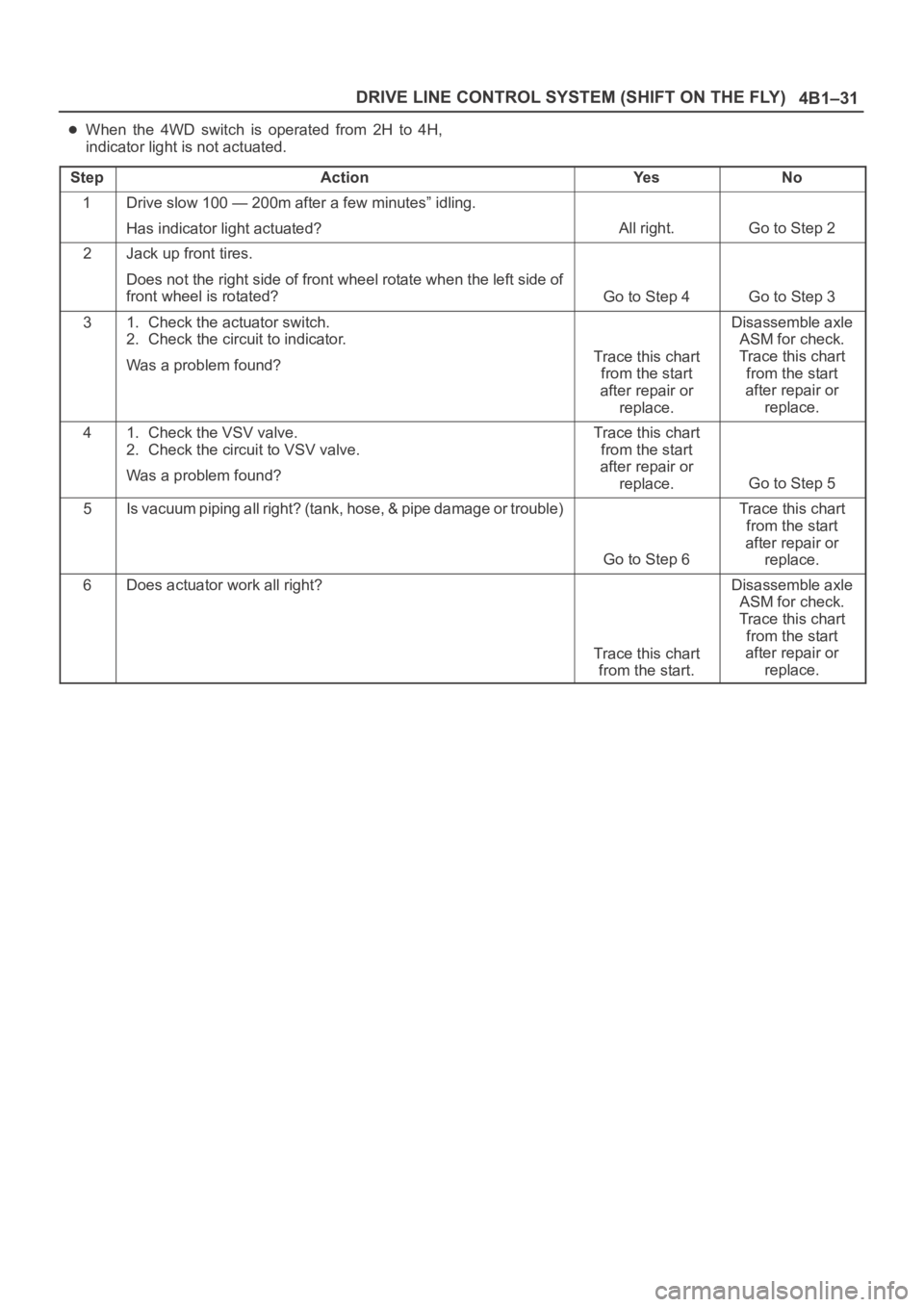
When the 4WD switch is operated from 2H to 4H,
indicator light is not actuated.
Step
ActionYe sNo
1Drive slow 100 — 200m after a few minutes” idling.
Has indicator light actuated?
All right.Go to Step 2
2Jack up front tires.
Does not the right side of front wheel rotate when the left side of
front wheel is rotated?
Go to Step 4Go to Step 3
31. Check the actuator switch.
2. Check the circuit to indicator.
Was a problem found?
Trace this chart
from the start
after repair or
replace.
Disassemble axle
ASM for check.
Trace this chart
from the start
after repair or
replace.
41. Check the VSV valve.
2. Check the circuit to VSV valve.
Was a problem found?Trace this chart
from the start
after repair or
replace.
Go to Step 5
5I s v a c u u m p i p i n g a l l r i g h t ? ( t a n k , h o s e , & p i p e d a m a g e o r t r o u ble)
Go to Step 6
Trace this chart
from the start
after repair or
replace.
6Does actuator work all right?
Trace this chart
from the start.
Disassemble axle
ASM for check.
Trace this chart
from the start
after repair or
replace.
Page 4085 of 6000
DRIVE LINE CONTROL SYSTEM (TOD) 4B2–2
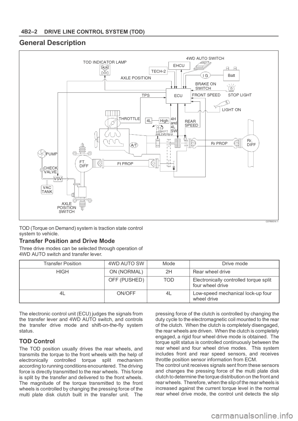
General Description
C07RW014–1
TOD (Torque on Demand) system is traction state control
system to vehicle.
Transfer Position and Drive Mode
Three drive modes can be selected through operation of
4WD AUTO switch and transfer lever.
Transfer Position
4WD AUTO SWModeDrive mode
HIGHON (NORMAL)2HRear wheel drive
OFF (PUSHED)TODElectronically controlled torque split
four wheel drive
4LON/OFF4LLow-speed mechanical lock-up four
wheel drive
The electronic control unit (ECU) judges the signals from
the transfer lever and 4WD AUTO switch, and controls
the transfer drive mode and shift-on-the-fly system
status.
TOD Control
The TOD position usually drives the rear wheels, and
transmits the torque to the front wheels with the help of
electronically controlled torque split mechanism
according to running conditions encountered. The driving
force is directly transmitted to the rear wheels. This force
is split by the transfer and delivered to the front wheels.
The magnitude of the torque transmitted to the front
wheels is controlled by changing the pressing force of the
multi plate disk clutch built in the transfer unit. Thepressing force of the clutch is controlled by changing the
duty cycle to the electromagnetic coil mounted to the rear
of the clutch. When the clutch is completely disengaged,
the rear wheels are driven. When the clutch is completely
engaged, a rigid four wheel drive mode is obtained. The
torque split status is controlled continuously between the
rear wheel and four wheel drive modes. This system
includes front and rear speed sensors, and receives
throttle position sensor information from ECM.
The control unit receives signals sent from these sensors
and changes the pressing force of the multi plate disk
clutch to determine the torque distribution on the front and
rear wheels. Therefore, when the slip of the rear wheels is
increased against the current torque level in the normal
rear wheel drive mode, the control unit detects the slip
Page 4086 of 6000
4B2–3 DRIVE LINE CONTROL SYSTEM (TOD)
condition, determines the optimum torque based on the
feedback control logic, and increases the torque to the
front wheels.
The control unit uses the signal from the throttle position
sensor to predict the future vehicle condition and the
intention of the driver with respect to acceleration and
deceleration, and determines the initial torque distribution
using these data and the information from the speed
sensors.
In case of small circle turning in the parking lot, for
example, the control unit minimizes the clutch pressing
force to restrict a braking phenomenon. When the ABS
becomes active, the control unit optimizes the clutch
pressing force to ensure stable braking.
TOD Indicator Control
The TOD indicator on the instrument panel informs the
driver of the current working status of the transfer unit.
The information consists of two items: the drive mode
(2H, TOD, 4L, transition) and the torque split status of the
TOD (torque distribution level). The indicator can display
occasional errors and corresponding error codes.
Page 4131 of 6000
DRIVE LINE CONTROL SYSTEM (TOD) 4B2–48
StepActionYe sNo
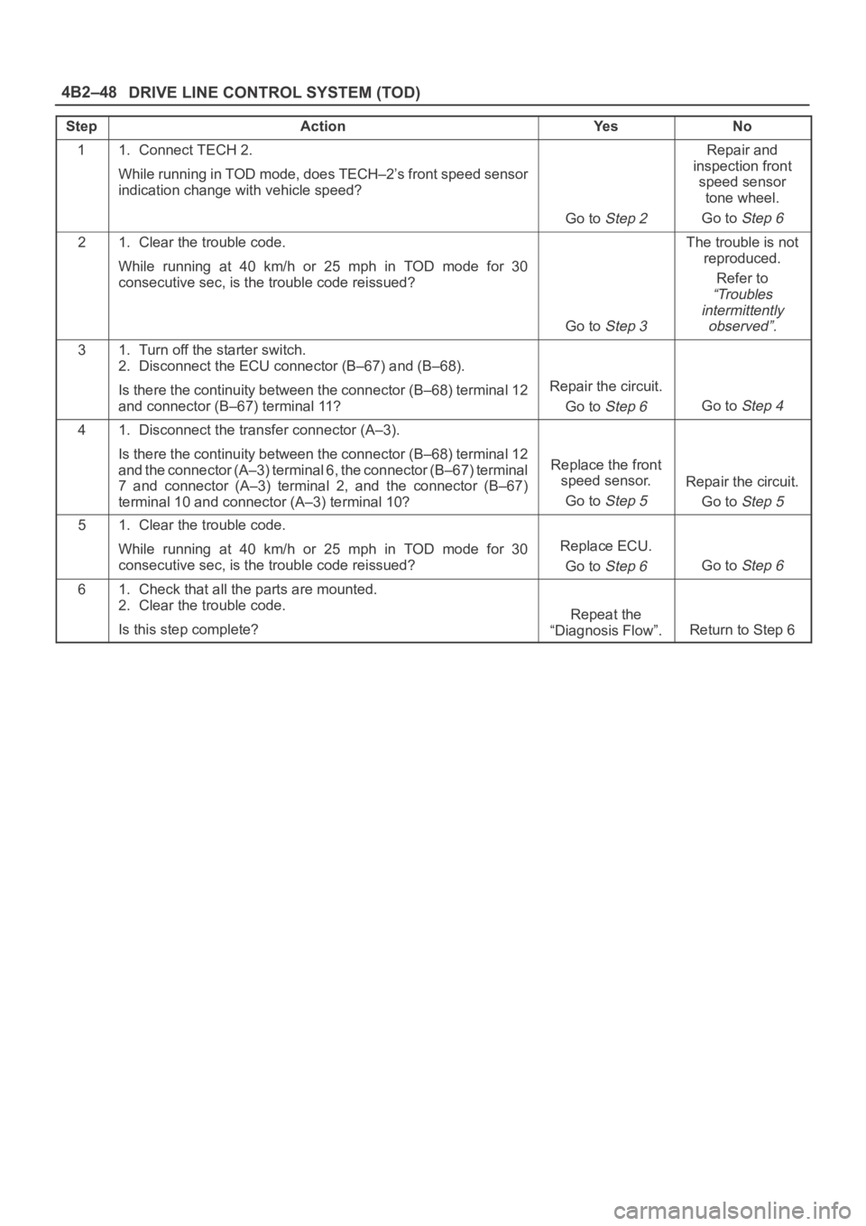
11. Connect TECH 2.
While running in TOD mode, does TECH–2’s front speed sensor
indication change with vehicle speed?
Go to Step 2
Repair and
inspection front
speed sensor
tone wheel.
Go to
Step 6
21. Clear the trouble code.
While running at 40 km/h or 25 mph in TOD mode for 30
consecutive sec, is the trouble code reissued?
Go to Step 3
The trouble is not
reproduced.
Refer to
“Troubles
intermittently
observed”.
31. Turn off the starter switch.
2. Disconnect the ECU connector (B–67) and (B–68).
Is there the continuity between the connector (B–68) terminal 12
and connector (B–67) terminal 11?
Repair the circuit.
Go to
Step 6Go to Step 4
41. Disconnect the transfer connector (A–3).
Is there the continuity between the connector (B–68) terminal 12
and the connector (A–3) terminal 6, the connector (B–67) terminal
7 and connector (A–3) terminal 2, and the connector (B–67)
terminal 10 and connector (A–3) terminal 10?
Replace the front
speed sensor.
Go to
Step 5
Repair the circuit.
Go to
Step 5
51. Clear the trouble code.
While running at 40 km/h or 25 mph in TOD mode for 30
consecutive sec, is the trouble code reissued?
Replace ECU.
Go to
Step 6Go to Step 6
61. Check that all the parts are mounted.
2. Clear the trouble code.
Is this step complete?
Repeat the
“Diagnosis Flow”.
Return to Step 6
Page 4133 of 6000
DRIVE LINE CONTROL SYSTEM (TOD) 4B2–50
StepActionYe sNo
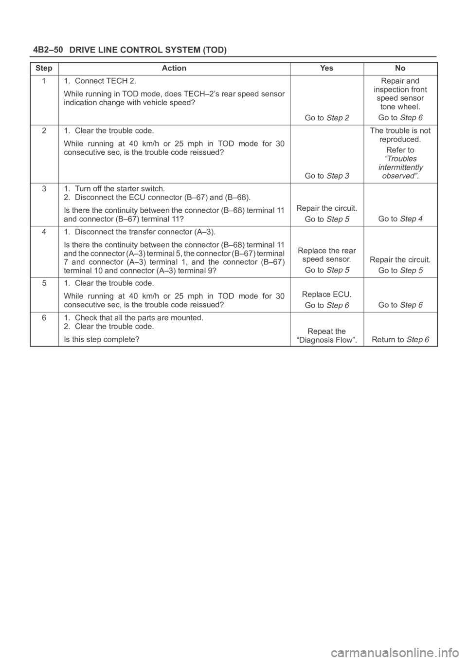
11. Connect TECH 2.
While running in TOD mode, does TECH–2’s rear speed sensor
indication change with vehicle speed?
Go to Step 2
Repair and
inspection front
speed sensor
tone wheel.
Go to
Step 6
21. Clear the trouble code.
While running at 40 km/h or 25 mph in TOD mode for 30
consecutive sec, is the trouble code reissued?
Go to Step 3
The trouble is not
reproduced.
Refer to
“Troubles
intermittently
observed”.
31. Turn off the starter switch.
2. Disconnect the ECU connector (B–67) and (B–68).
Is there the continuity between the connector (B–68) terminal 11
and connector (B–67) terminal 11?
Repair the circuit.
Go to
Step 5Go to Step 4
41. Disconnect the transfer connector (A–3).
Is there the continuity between the connector (B–68) terminal 11
and the connector (A–3) terminal 5, the connector (B–67) terminal
7 and connector (A–3) terminal 1, and the connector (B–67)
terminal 10 and connector (A–3) terminal 9?
Replace the rear
speed sensor.
Go to
Step 5
Repair the circuit.
Go to
Step 5
51. Clear the trouble code.
While running at 40 km/h or 25 mph in TOD mode for 30
consecutive sec, is the trouble code reissued?
Replace ECU.
Go to
Step 6Go to Step 6
61. Check that all the parts are mounted.
2. Clear the trouble code.
Is this step complete?
Repeat the
“Diagnosis Flow”.
Return to Step 6