Page 4012 of 6000

DIFFERENTIAL (REAR 244mm)
4A2B–5
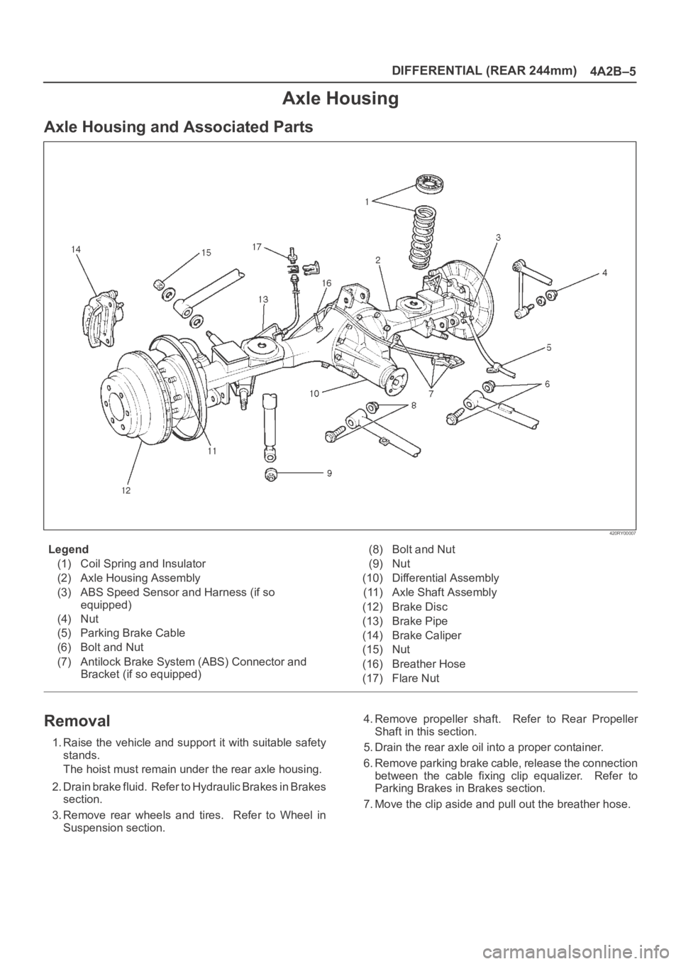
Axle Housing
Axle Housing and Associated Parts
420RY00007
Legend
(1) Coil Spring and Insulator
(2) Axle Housing Assembly
(3) ABS Speed Sensor and Harness (if so
equipped)
(4) Nut
(5) Parking Brake Cable
(6) Bolt and Nut
(7) Antilock Brake System (ABS) Connector and
Bracket (if so equipped)(8) Bolt and Nut
(9) Nut
(10) Differential Assembly
(11) Axle Shaft Assembly
(12) Brake Disc
(13) Brake Pipe
(14) Brake Caliper
(15) Nut
(16) Breather Hose
(17) Flare Nut
Removal
1. Raise the vehicle and support it with suitable safety
stands.
The hoist must remain under the rear axle housing.
2. Drain brake fluid. Refer to Hydraulic Brakes in Brakes
section.
3. Remove rear wheels and tires. Refer to Wheel in
Suspension section.4. Remove propeller shaft. Refer to Rear Propeller
Shaft in this section.
5. Drain the rear axle oil into a proper container.
6. Remove parking brake cable, release the connection
between the cable fixing clip equalizer. Refer to
Parking Brakes in Brakes section.
7. Move the clip aside and pull out the breather hose.
Page 4014 of 6000

DIFFERENTIAL (REAR 244mm)
4A2B–7
11. Install the lateral rod fixing nut to the axle housing.
12. Install the stabilizer linkage mounting nut to the axle
housing.
13. Install the shock absorber fixing nut to the axle
housing.
14. Install brake tube flare nut, Refer to Disk Brakes in
Brake section.15. Install ABS connector and bracket (if so equipped).
16. Connect breather hose.
17. Install parking brake cable, Refer to Parking Brakes in
Brake section.
18. Bleed brakes. Refer to Hydraulic Brakes in Brake
section.
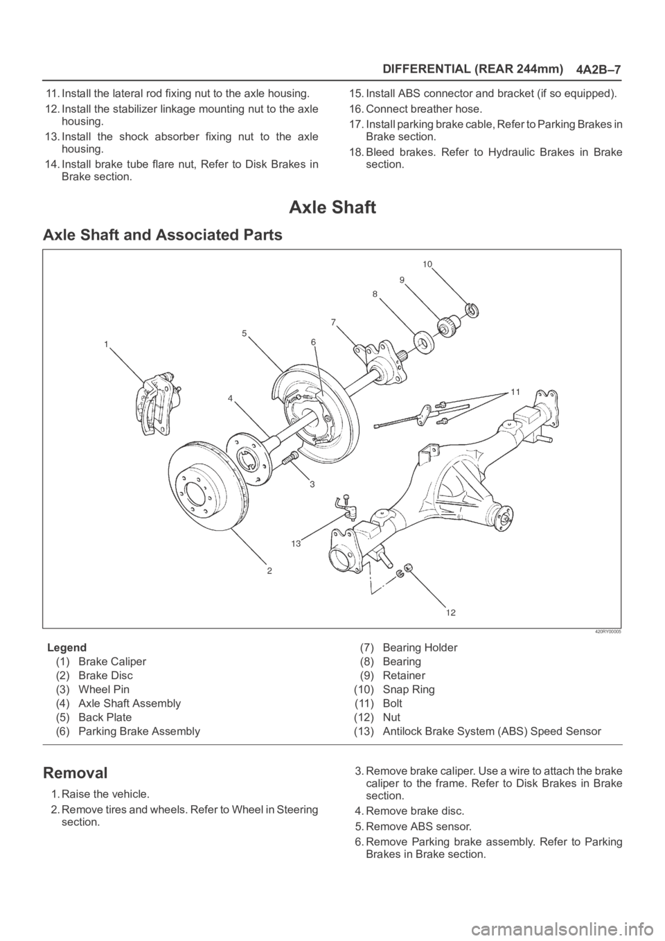
Axle Shaft
Axle Shaft and Associated Parts
420RY00005
Legend
(1) Brake Caliper
(2) Brake Disc
(3) Wheel Pin
(4) Axle Shaft Assembly
(5) Back Plate
(6) Parking Brake Assembly(7) Bearing Holder
(8) Bearing
(9) Retainer
(10) Snap Ring
(11) Bolt
(12) Nut
(13) Antilock Brake System (ABS) Speed Sensor
Removal
1. Raise the vehicle.
2. Remove tires and wheels. Refer to Wheel in Steering
section.3. Remove brake caliper. Use a wire to attach the brake
caliper to the frame. Refer to Disk Brakes in Brake
section.
4. Remove brake disc.
5. Remove ABS sensor.
6. Remove Parking brake assembly. Refer to Parking
Brakes in Brake section.
Page 4015 of 6000
4A2B–8DIFFERENTIAL (REAR 244mm)
7.Remove the parking brake cable mounting
bolts(Behind the back plate)(1).
311RS001
8. Remove the bearing holder mounting nuts.
9. Remove axle shaft assembly.
NOTE: Be sure not to damage the oil seal.
10. Remove snap ring.
11. Using a bearing remover 5–8840–2295–0 and press,
remove retainer together with the bearing holder.
420RY00012
12. Remove bearing.
13. Remove bearing holder.
14. Remove back plate.15. Remove the wheel pins using a remover
5–8840–0029–0.
420RY00011
Inspection and Repair
Make necessary correction or parts replacement if wear,
corrosion or any other abnormal conditions are found
through inspection.
Visual Check:
Check the following parts for wear, damage, noise or any
other abnormal conditions:
1. Axle shaft
2. Bearing
When checking the axle shaft, pay special attention to the
splined portions and replace the shaft if distortion or step
wear is noticeable. Correct slight step wear with a grinder.
420RS008
Page 4016 of 6000
DIFFERENTIAL (REAR 244mm)
4A2B–9
Axle Shaft Run–out
Limit: 1.0 mm (0.039 in)
420RS009
Axle Shaft Flange Run–out
Limit: 0.08 mm (0.003 in)
420RS010
Oil Seal Replacement
Remove the oil seal carefully not to damage the bearing
holder bore .
When installing, use oil seal installer 5–8840–2310–0.
420RY00009
Installation
1. Install wheel pin.
2. Install back plate.
3. Install bearing holder.
4. Install bearing.
5. Install retainer by using a bearing installer
5–8840–2296–0, press fit together with the bearing.
420RY00010
Page 4019 of 6000
4A2B–12DIFFERENTIAL (REAR 244mm)
Differential Assembly
Differential Assembly and Associated Parts
425RY00016
Legend
(1) Bolt and Nut
(2) Axle Shaft Assembly(3) Parking Brake Cable
(4) Differential Assembly
(5) Nut
Removal
1. Jack up and support the frame with stands.
2. Remove the wheel and tire. Refer to Wheel in
Steering section.
3. Drain the differential oil.
4. Remove the propeller shaft. Refer to Rear Propeller
Shaft in this section.
5. Remove the ABS speed sensor. Refer to Anti–lock
Brake System in Brakes section.6. Remove the parking brake cable fastening clip and
disconnect the equalizer section. Refer to Parking
Brakes in Brake section.
7. Remove the bearing holder fixing nuts.
8. Remove axle shaft assembly, be sure not to damage
the oil seal by axle shaft.
9. Remove differential carrier mounting bolts and nuts.
10. Remove differential assembly.
Page 4034 of 6000
DIFFERENTIAL (REAR 244mm)
4A2B–27
2. Adjust the backlash between the side gear and
the pinion gear.
Backlash: 0.15 – 0.20 mm (0.006 – 0.008 in)
Thickness of thrust washers available
mm
0.800.901.001.101.201.30
in0.0310.0350.0390.0430.0470.051
425RY00008
4. Install lock pin.
Install the lock pin using small drift.
425RY00009
5. Install exciter ring (If equipped with rear wheel
antilock).
Press the exciter ring on the differential cage using
the ring gear as a pilot.
NOTE: Discard used exciter ring and install new one.
425RS052
6. Tighten the bolts in diagonal sequence as illustrated.
Torque: 127Nꞏm (13.0kgꞏm/94 lb ft)
NOTE: Discard used bolts and install new ones.
425RW033
Page 4047 of 6000
4B1–2
DRIVE LINE CONTROL SYSTEM (SHIFT ON THE FLY)
Shift on the Fly System (Lever Type)
Outline of Shift on the Fly System
(Lever Type)
The shift on the fly system (Lever type) switches between
2 wheel drive (2WD) and 4 wheel drive (4WD) by driver’s
shifting the transfer control lever on the floor.
This system controls below operations.
1. Connecting front wheels to, and disconnecting them
from, the front axles by vacuum actuator.
2. Indicator on instrument panel.
3. 4WD signal to Electronic Hydraulic Control Unit for
brake system (If anti–lock brake system is equipped).
Page 4052 of 6000
4B1–7 DRIVE LINE CONTROL SYSTEM (SHIFT ON THE FLY)
Shift on the Fly System (Push Button Type)
Outline of Shift on the Fly System (Push Button Type)
The shift on the fly system switches between 2 wheel
drive (2WD) and 4 wheel drive (4WD) electrically by
driver’s pressing the 4WD switch (push button type) on
instrument panel.
This system controls below operations. (Shifting between
“4H” and “4L” must be performed by transfer control lever
on the floor.)
1. Shifting the transfer front output gear (Connecting to,
and disconnecting from, front propeller shaft by motor
actuator).2. Retrial of shifting the transfer front output gear.
3. Connecting front wheels to, and disconnecting them
from, the front axles by vacuum actuator.
4. Indicator on instrument panel.
5. 4WD out signal to other Electronic Hydraulic Control
Unit (If anti–lock brake system is equipped).
System Diagrams
412RW050