1998 OPEL FRONTERA wheel
[x] Cancel search: wheelPage 3445 of 6000
SUPPLEMENTAL RESTRAINT SYSTEM 9J–8
the deployment loops, high resistance or opens in the
“Driver Side High”, “Driver Side Low”, “Passenger Side
High” and “Passenger Side Low” circuits and measures
the resistance of the inflator assembly consisting of 1)
Initiators, 2) SRS coil assembly (driver side only), 3)
Connectors and associated wiring.
Normal Operating Voltage Range
The voltage measured between the SDM “Ignition 1”
terminals and “Ground” terminals is between 9 and 16
volts.
Passenger Current Source
An output of the SDM which applies current into the
passenger air bag assembly circuit during the “Initiator
Assembly Resistance Test”.
Passenger Air Bag Assembly
An assembly located in the right side of the instrument
panel consisting of an inflatable bag, an inflator and an
initiator.
Scan Tool
An external computer used to read diagnostic information
from on–board computers via the data link connector.
SDM
Sensing and Diagnostic Module which provides reserve
energy to the deployment loops, deploys the air bags
when required and performs diagnostic monitoring of all
SRS components.
Serial Data
Information representing the status of the SRS.
SRS
Supplemental Restraint System.
SRS Coil Assembly
An assembly of two current–carrying coils in the driver
deployment loop that allows the rotation of the steering
wheel while maintaining the continuous contact of the
driver deployment loop to the driver air bag assembly.
SRS Wiring Harness
The wires and connectors that electrically connect the
components in the SRS.
“Turn–ON”
Test which the SDM performs on the SRS once during
each ignition cycle immediately after “Ignition 1” voltage
is applied to the SDM and before “Continuous
Monitoring”.
Diagnosis
WARNING: TO AVOID DEPLOYMENT WHEN
TROUBLESHOOTING THE SRS, DO NOT USE
ELECTRICAL TEST EQUIPMENT SUCH AS A
BATTERY–POWERED OR AC–POWERED
VOLTMETER, OHMMETER, ETC., OR ANY TYPE OF
ELECTRICAL EQUIPMENT OTHER THAN THAT
SPECIFIED IN THIS MANUAL. DO NOT USE A
NONPOWERED PROBE–TYPE TESTER.
INSTRUCTIONS IN THIS MANUAL MUST BE
FOLLOWED CAREFULLY, OTHERWISE PERSONAL
INJURY MAY RESULT.
Diagnostic Trouble Codes
The “SRS Diagnostic System Check” must always be the
starting point of any SRS diagnosis. The “SRS
Diagnostic System Check” checks for proper “AIR BAG”
warning lamp operation and checks for SRS diagnostic
trouble codes using the scan tool.
1. Current diagnostic trouble codes – Malfunctions that
are presently being detected. Current diagnostic
trouble codes are stored in RAM (Random Access
Memory).
2. History diagnostic trouble codes – All malfunctions
detected since the last time the history memory was
cleared. History diagnostic trouble codes are stored
in EEPROM.
Scan Tool Diagnostics
A scan tool is used to read current and history diagnostic
trouble codes and to clear all diagnostic trouble codes
after a repair is completed. The scan tool must be
updated to communicate with the SRS through a
replaceable cartridge before it can be used for SRS
diagnostics. To use the scan tool, connect it to the data
link connector and turn the ignition switch “ON”. The scan
tool reads serial data from the SDM “Serial Data” line
terminal “24” to the data link connector terminal “9”.
Use Of Special Tools
WARNING: TO AV O I D D E P L O Y M E N T W H E N
TROUBLESHOOTING THE SRS, DO NOT USE
ELECTRICAL TEST EQUIPMENT SUCH AS A
BATTERY–POWERED OR AC–POWERED
VOLTMETER, OHMMETER, ETC, OR ANY TYPE OF
ELECTRICAL EQUIPMENT OTHER THAN THAT
SPECIFIED IN THIS MANUAL. DO NOT USE A NON
POWERED PROBE–TYPE TESTER. INSTRUCTIONS
IN THIS MANUAL MUST BE FOLLOWED
CAREFULLY, OTHERWISE PERSONAL INJURY MAY
RESULT. YOU SHOULD BE FAMILIAR WITH THE
TOOLS LISTED IN THIS SECTION UNDER THE
HANDLING SRS SPECIAL TOOLS.
You should be able to measure voltage and resistance.
You should be familiar with proper use of a scan tool such
as the Tech 2 Diagnostic Computer, SRS
Driver/Passenger Load Tool 5–8840–2421–0, Connector
Test Adapter Kit 5–8840–0385–0, and the DVM (Digital
Multimeter) 5–8840–0285–0.
Page 3449 of 6000
SUPPLEMENTAL RESTRAINT SYSTEM 9J–12
Deployed Air Bag Assembly (Driver Side)
“You should wear gloves and glasses. After the air bag
assembly has been deployed, the surface of the air bag
may contain solid particulate. This solid particulate
c o n s i s t s p r i m a r i l y o f b y p r oducts of the chemical reaction,
Potassium Chloride and copper metal dust. Compounds
of Potassium Borate, Strontium Chloride, Copper
Chloride, and Ammonium Chloride may be found in
amounts of about 1% (each) of the total particulate.”
Deployed Pretensioner Seat Belt.
You should wear gloves and safety glasses. After the
pretensioner seat belt has been deployed, the surface of
the pretensioner seat belt cylinder may heating up.
Air Bag Assembly and/or Pretensioner
Seat Belt Scrapping Procedure.
During the cause of vehicle’s useful life, certain situations
may arise which will necessitate the disposal of a live air
bag and/or pretensioner seat belt. (This information
covers proper procedures for disposing of a live air bag
assembly and/or pretensioner seat belt.)
Before a live air bag assembly can be dispose off, it must
be deployed.
A live air bag assembly and/or pretensioner seat belt
must not be disposed of though normal refuse channels.
WARNING: FAILURE TO FOLLOW PROPER
SUPPLEMENTAL RESTRAINT SYSTEM (SRS) AIR
BAG ASSEMBLY DISPOSAL PROCEDURES CAN
RESULT IN AIR BAG DEPLOYMENT WHICH MAY
CAUSE PERSONAL INJURY. AN UNDPLOYED AIR
BAG ASSEMBLY MUST NOT BE DISPOSED OF
THROUGH NORMAL REFUSE CHANNELS. THE
UNDEPLOYED AIR BAG ASSEMBLY CONTAINS
SUBSTANCES THAT CAN CAUSE SEVERE ILLNESS
OR PERSONAL INJURY IF THE SEALED CONTAINER
IS DAMAGED DURING DISPOSAL. DISPOSAL IN
ANY MANNER INCONSISTENT WITH PROPER
PROCEDURES MAY BE A VIOLATION OF LOCAL
LAW.
In situations which require deployment of a live air bag
assembly, deployment may be accomplished inside or
outside the vehicle. The method employed depends
upon the final disposition of the particular vehicle, as
noted in “Deployment Outside Vehicle” and “Deployment
Inside Vehicle” in this section.
Cautions About Air Bag Deployment And
Disposal
Failure to follow proper procedures could result in
erroneous air bag deployment which may cause personal
injury be sure to follow proper procedures.
1. Turn off (Lock) the ignition switch and disconnect the
minus terminal of the battery, then start the work 15 or
more sec later. (Air bag is designed to work by the
back-up power source even if the battery power
source is cut off at vehicle collision).
2. Be sure not to disassemble the air bag.
3. Do not give an impact to the air bag and bring the air
bag close to magnet. (The air bag could deploy
unexpectedly).4. Place the air bag with its trim cover up.
5. Do not let the air bag deploy directly on the floor. (The
air bag may be blown off 2
3 m (6.5 or 10 feet)).
6. Be sure to install the air bag firmly to a deployment
tool (fixing tool).
7. Set a battery 10 m (33 feet) or more away from the air
bag.
8. Before disconnecting air bag harness, ground the
worker by touching the vehicle outer panel with bare
hand.
9. When connecting or disconnecting the harness, do
not work just in front of the air bag.
10. As deployment gives rise to big sound, warn the
people around against it. Further, try to reduce the
sound by covering the steering wheel or tires, and
shut the vehicle windows in case of deployment
inside the vehicle.
11. As deployment generates smoke, select a well
ventilated place. (In case of deployment indoors,
avoid deployment just under a fire alarm, smoke
sensor, and fluorescent lamps).
12. Be careful not to inhale the smoke after deployment.
13. If part of the vehicle glass is damaged, cover the
vehicle with a car cover to prevent the glass from
braking at the time of deployment.
14. Do not touch the air bag immediately after
deployment, since it remains hot for 30 minutes.
15. Do not water the air bag immediately after
deployment.
16. Wear safety glasses and gloves throughout the work
and wash the glasses and gloves after the work.
17. Do not reuse the removed air bag for another vehicle.
(Deployment characteristic is different with vehicle
types).
Deployment Outside Vehicle (Driver Air
Bag Assembly)
Deployment outside the vehicle is proper when the
vehicle is to be returned to service. This includes, for
example, situations in which the vehicle will be returned to
useful service after a functionally or cosmetically deficient
air bag assembly is replaced. Deployment and disposal
of a malfunctioning air bag assembly is, of course, subject
to any required retention period.
For deployment of a live (undeployed) air bag assembly
outside the vehicle, the deployment procedure must be
followed exactly. Always wear safety glasses during this
deployment procedure until a deployed air bag assembly
is scrapped or until an undeployed air bag assembly is
shipped. Before performing the procedures you should
be familiar with servicing the SRS and with proper
handling of the air bag assembly. Procedures should be
read fully before they are performed.
The following procedure requires use of 5–8840–2468–0
SRS deployment harness with appropriate pigtail
adapter. Do not attempt procedure without
5–8840–2468–0 adapter.
WARNING: FAILURE TO FOLLOW PROCEDURES IN
THE ORDER LISTED MAY RESULT IN PERSONAL
INJURY. NEVER CONNECT DEPLOYMENT
Page 3455 of 6000
SUPPLEMENTAL RESTRAINT SYSTEM 9J–18
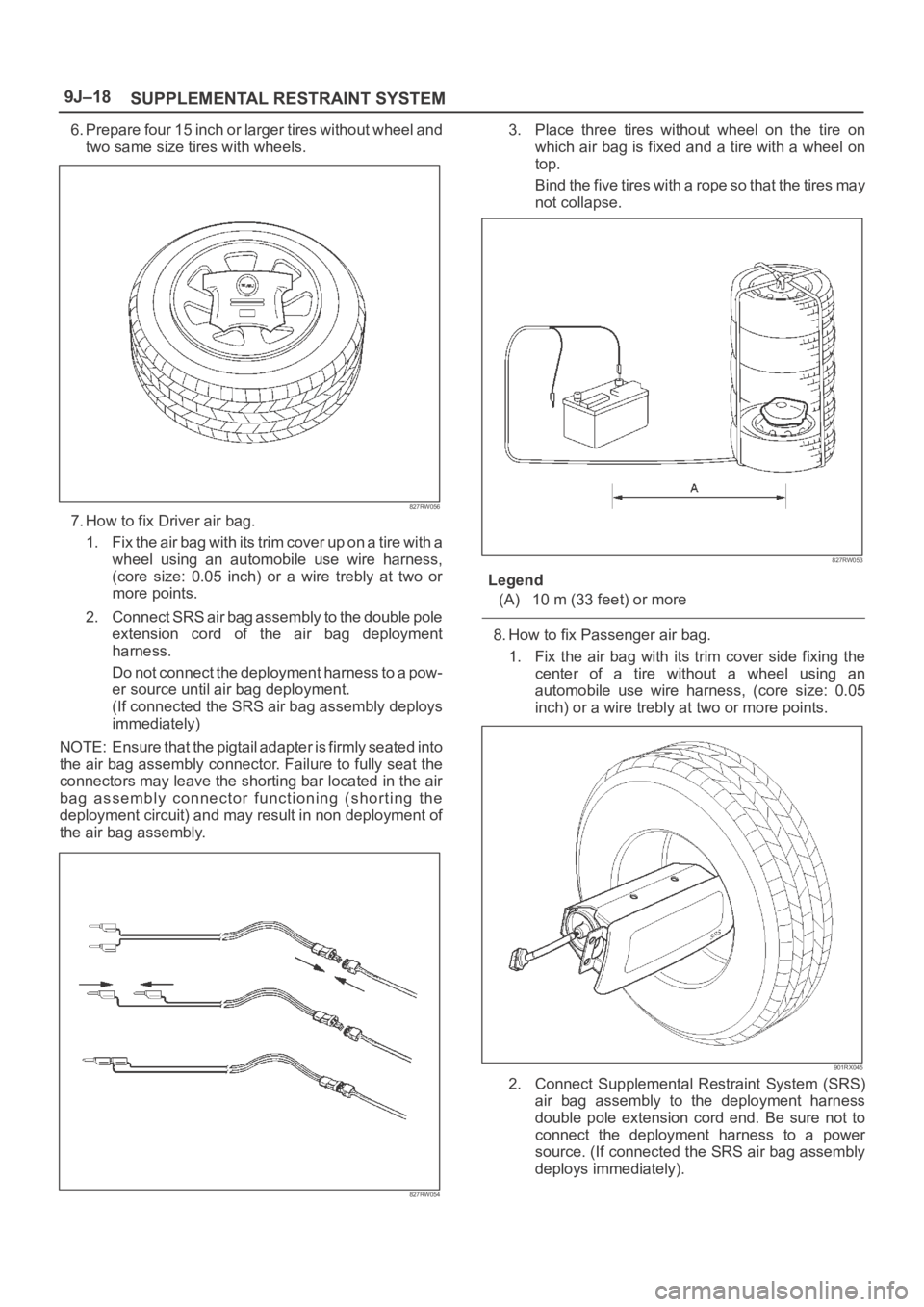
6. Prepare four 15 inch or larger tires without wheel and
two same size tires with wheels.
827RW056
7. How to fix Driver air bag.
1. Fix the air bag with its trim cover up on a tire with a
wheel using an automobile use wire harness,
(core size: 0.05 inch) or a wire trebly at two or
more points.
2. Connect SRS air bag assembly to the double pole
extension cord of the air bag deployment
harness.
Do not connect the deployment harness to a pow-
er source until air bag deployment.
(If connected the SRS air bag assembly deploys
immediately)
NOTE: Ensure that the pigtail adapter is firmly seated into
the air bag assembly connector. Failure to fully seat the
connectors may leave the shorting bar located in the air
bag assembly connector functioning (shorting the
deployment circuit) and may result in non deployment of
the air bag assembly.
827RW054
3. Place three tires without wheel on the tire on
which air bag is fixed and a tire with a wheel on
top.
Bind the five tires with a rope so that the tires may
not collapse.
827RW053
Legend
(A) 10 m (33 feet) or more
8. How to fix Passenger air bag.
1. Fix the air bag with its trim cover side fixing the
center of a tire without a wheel using an
automobile use wire harness, (core size: 0.05
inch) or a wire trebly at two or more points.
901RX045
2. Connect Supplemental Restraint System (SRS)
air bag assembly to the deployment harness
double pole extension cord end. Be sure not to
connect the deployment harness to a power
source. (If connected the SRS air bag assembly
deploys immediately).
Page 3456 of 6000
SUPPLEMENTAL RESTRAINT SYSTEM9J–19
NOTE: Ensure that the pigtail adapter is firmly seated into
the air bag assembly connector. Failure to fully seat the
connectors may leave the shorting bar located in the air
bag assembly connector functioning (shorting the
deployment circuit) and may result in non deployment of
the air bag assembly.
827RW054
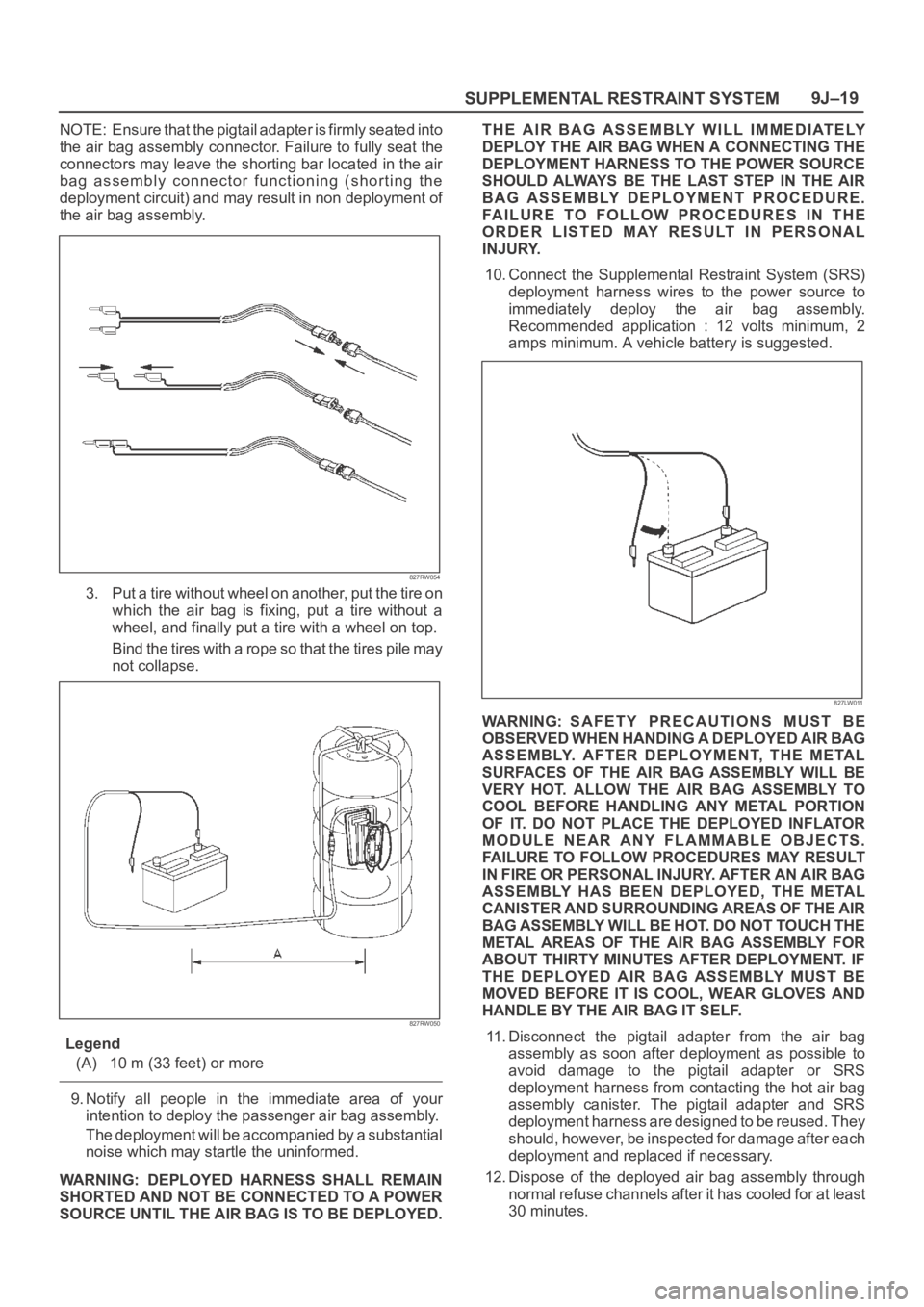
3. Put a tire without wheel on another, put the tire on
which the air bag is fixing, put a tire without a
wheel, and finally put a tire with a wheel on top.
Bind the tires with a rope so that the tires pile may
not collapse.
827RW050
Legend
(A) 10 m (33 feet) or more
9. Notify all people in the immediate area of your
intention to deploy the passenger air bag assembly.
The deployment will be accompanied by a substantial
noise which may startle the uninformed.
WARNING: DEPLOYED HARNESS SHALL REMAIN
SHORTED AND NOT BE CONNECTED TO A POWER
SOURCE UNTIL THE AIR BAG IS TO BE DEPLOYED.THE AIR BAG ASSEMBLY WILL IMMEDIATELY
DEPLOY THE AIR BAG WHEN A CONNECTING THE
DEPLOYMENT HARNESS TO THE POWER SOURCE
SHOULD ALWAYS BE THE LAST STEP IN THE AIR
BAG ASSEMBLY DEPLOYMENT PROCEDURE.
FAILURE TO FOLLOW PROCEDURES IN THE
ORDER LISTED MAY RESULT IN PERSONAL
INJURY.
10. Connect the Supplemental Restraint System (SRS)
deployment harness wires to the power source to
immediately deploy the air bag assembly.
Recommended application : 12 volts minimum, 2
amps minimum. A vehicle battery is suggested.
827LW011
WARNING: SAFETY PRECAUTIONS MUST BE
OBSERVED WHEN HANDING A DEPLOYED AIR BAG
ASSEMBLY. AFTER DEPLOYMENT, THE METAL
SURFACES OF THE AIR BAG ASSEMBLY WILL BE
VERY HOT. ALLOW THE AIR BAG ASSEMBLY TO
COOL BEFORE HANDLING ANY METAL PORTION
OF IT. DO NOT PLACE THE DEPLOYED INFLATOR
MODULE NEAR ANY FLAMMABLE OBJECTS.
FAILURE TO FOLLOW PROCEDURES MAY RESULT
I N F IR E O R PE RSO NAL IN JU RY. A FT ER A N A IR BAG
ASSEMBLY HAS BEEN DEPLOYED, THE METAL
CANISTER AND SURROUNDING AREAS OF THE AIR
BAG ASSEMBLY WILL BE HOT. DO NOT TOUCH THE
METAL AREAS OF THE AIR BAG ASSEMBLY FOR
ABOUT THIRTY MINUTES AFTER DEPLOYMENT. IF
THE DEPLOYED AIR BAG ASSEMBLY MUST BE
MOVED BEFORE IT IS COOL, WEAR GLOVES AND
HANDLE BY THE AIR BAG IT SELF.
11. Disconnect the pigtail adapter from the air bag
assembly as soon after deployment as possible to
avoid damage to the pigtail adapter or SRS
deployment harness from contacting the hot air bag
assembly canister. The pigtail adapter and SRS
deployment harness are designed to be reused. They
should, however, be inspected for damage after each
deployment and replaced if necessary.
12. Dispose of the deployed air bag assembly through
normal refuse channels after it has cooled for at least
30 minutes.
Page 3467 of 6000
SUPPLEMENTAL RESTRAINT SYSTEM 9J–30
Service Precautions for SRS
Component Service
CAUTION: When fasteners are removed, always
reinstall them at the same location from which they
were removed. If a fastener needs to be replaced, use
the correct part number fastener for that application.
If the correct part number fastener is not available, a
fastener of equal size and strength (or stronger) may
be used. fasteners that are not reused, and those
requiring thread locking compound will be called
out. The correct torque value must be used when
installing fasteners that require it. If the above
conditions are not followed, parts or system damage
could result.
WARNING: WHEN PERFORMING SERVICE ON OR
AROUND SRS COMPONENTS OR SRS WIRING,
FOLLOW THE PROCEDURES LISTED BELOW TO
TEMPORARILY DISABLE THE SRS. FAILURE TO
FOLLOW PROCEDURES COULD RESULT IN
POSSIBLE AIR BAG DEPLOYMENT, PERSONAL
INJURY OR OTHERWISE UNNEEDED SRS REPAIRS.
The SDM in Driver–Passenger SRS can maintain
sufficient voltage to cause a deployment for up to 15
seconds after the ignition switch is turned “OFF,” the
battery is disconnected, or the fuse powering the SDM is
removed.
Many of the service procedures require removal of the
“C–21” fuse, and disconnection of the air bag assembly
from the deployment loop to avoid an accidental
deployment. If the air bag assembly is disconnected from
the deployment loop as noted in the “Disabling the SRS”
procedure that follows, service can begin immediately
without waiting for the 15 second time period to expire.
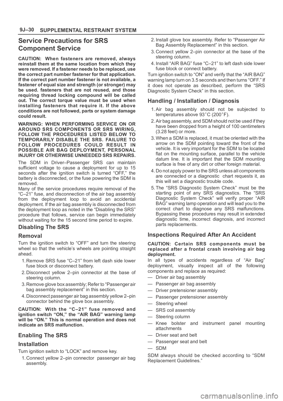
Disabling The SRS
Removal
Turn the ignition switch to “OFF” and turn the steering
wheel so that the vehicle’s wheels are pointing straight
ahead.
1. Remove SRS fuse “C–21” from left dash side lower
fuse block or disconnect battery.
2. Disconnect yellow 2–pin connector at the base of
steering column.
3 . R e m o v e g l o v e b o x a s s e m b l y ; R e f e r t o “ P a s s e n g e r a i r
bag assembly replacement” in this section.
4. Disconnect passenger air bag assembly yellow 2–pin
connector behind the glove box assembly.
CAUTION: W i t h t h e “ C – 2 1 ” f u s e r e m o v e d a n d
ignition switch “ON,” the “AIR BAG” warning lamp
will be “ON.” This is normal operation and does not
indicate an SRS malfunction.
Enabling The SRS
Installation
Turn ignition switch to “LOCK” and remove key.
1. Connect yellow 2–pin connector passenger air bag
assembly.2. Install glove box assembly. Refer to “Passenger Air
Bag Assembly Replacement” in this section.
3. Connect yellow 2–pin connector at the base of the
steering column.
4. Install “AIR BAG” fuse “C–21” to left dash side lower
fuse block or connect battery.
Turn ignition switch to “ON” and verify that the “AIR BAG”
warning lamp turn on 3.5 seconds and then turns “OFF.” If
it does not operate as described, perform the “SRS
Diagnostic System Check” in this section.
Handling / Installation / Diagnosis
1. Air bag assembly should not be subjected to
temperatures above 93
C (200F).
2. Air bag assembly, and SDM should not be used if they
have been dropped from a height of 100 centimeters
(3.28 feet) or more.
3. When a SDM is replaced, it must be oriented with the
arrow on the SDM pointing toward the front of the
vehicle. It is very important for the SDM to be located
flat on the mounting surface, parallel to the vehicle
datum line. It is important that the SDM mounting
surface is free of any dirt or other foreign material.
4. Do not apply power to the SRS unless all components
are connected or a diagnostic chart requests it, as
this will set a diagnostic trouble code.
5. The “SRS Diagnostic System Check” must be the
starting point of any SRS diagnostics. The “SRS
Diagnostic System Check” will verify proper “AIR
BAG” warning lamp operation and will lead you to the
correct chart to diagnose any SRS malfunctions.
Bypassing these procedures may result in extended
diagnostic time, incorrect diagnosis, and incorrect
parts replacements.
Inspections Required After An Accident
CAUTION: C e r t a i n S R S c o m p o n e n t s m u s t b e
replaced after a frontal crash involving air bag
deployment.
In all types of accidents regardless of “Air Bag”
deployment, visually inspect all of the following
components and replace as required:
— Driver air bag assembly
— Passenger air bag assembly
— Driver pretensioner assembly
— Passenger pretensioner assembly
— Steering wheel
— SRS coil assembly
— Steering column
— Knee bolster and instrument panel mounting
attachments
— Driver seat and belt
— Passenger seat and belt
—SDM
SDM always should be checked according to “SDM
Replacement Guidelines.”
Page 3468 of 6000
SUPPLEMENTAL RESTRAINT SYSTEM9J–31
CAUTION: Refer to “SDM Replacement Guidelines”
below for important information on SDM
replacement in both deployment and
non–deployment crashes.
Inspect SRS coil assembly wiring and steering wheel for
any sign of scorching, melting, or damage due to
excessive heat. If coil assembly wire or steering wheel is
damaged, replace them. The steering column and wheel
must be dimensionally checked to determine if they are
damaged. Refer to steering wheel of in this manual.
Never use SRS parts from another vehicle. This does not
include remanufactured parts purchased from an
authorized Isuzu Retailer; they may be used for SRS
repairs.
Do not attempt to repair the SDM, the SRS harness, the
SRS coil assembly, the air bag assembly, the steering
wheel, or the steering column. Service of these items is
replacement only. Verify replacement part numbers.
CAUTION: Proper operation of the SDM and
supplemental restraint system (SRS) requires that
any repairs to the vehicle structure return it to its
original production configuration.
SRS Connectors
CAUTION:The special yellow color connectors are
used for supplemental restraint system air bag circuit.
When removing the oable harnese, do not pull the cables
otherwile, cable disconnection may occur. When connect
the SRS connector, insert the connector completely.
Imperfect locking may cause malfunction of SRS circuit.
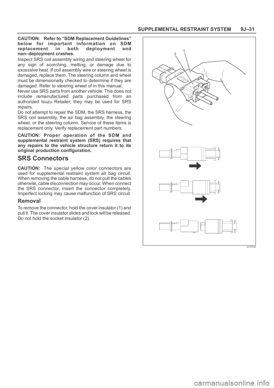
Removal
To remove the connector, hold the cover insulator (1) and
pull it. The cover insulator slides and lock will be released.
Do not hold the socket insulator (2).
827RW028
Page 3472 of 6000
SUPPLEMENTAL RESTRAINT SYSTEM9J–35
Driver Air Bag Assembly
Service Precautions
WARNING: SAFETY PRECAUTIONS MUST BE
FOLLOWED WHEN HANDLING A DEPLOYED AIR
BAG ASSEMBLY. AFTER DEPLOYMENT, THE AIR
BAG ASSEMBLY SURFACE MAY CONTAIN A SMALL
AMOUNT OF SODIUM HYDROXIDE, A BY–PRODUCT
OF THE DEPLOYMENT REACTION, THAT IS
IRRITATING TO THE SKIN AND EYES. MOST OF THE
POWER ON THE AIR BAG ASSEMBLY IS
HARMLESS. AS A PRECAUTION, WEAR GLOVES
AND SAFETY GLASSES WHEN HANDLING A
DEPLOYED AIR BAG ASSEMBLY, AND WASH YOUR
HANDS WITH MILD SOAP AND WATER
AFTERWARDS.
WARNING: WHEN CARRYING A LIVE AIR BAG
ASSEMBLY, MAKE SURE THE BAG AND TRIM
COVER ARE POINTED AWAY FROM YOU. NEVER
CARRY AIR BAG ASSEMBLY BY THE WIRES OR
CONNECTOR ON THE UNDERSIDE OF MODULE. IN
THE CASE OF AN ACCIDENTAL DEPLOYMENT, THE
BAG WILL THEN DEPLOY WITH MINIMAL CHANCE
OF INJURY. WHEN PLACING ALIVE AIR BAG
ASSEMBLY ON A BENCH OR OTHER SURFACE,
ALWAYS FACE BAG AND TRIM COVER UP, AWAY
FROM THE SURFACE. NEVER REST A STEERING
COLUMN ASSEMBLY ON THE STEERING WHEEL
WITH THE AIR BAG ASSEMBLY FACE DOWN AND
COLUMN VERTICAL. THIS IS NECESSARY SO THAT
A FREE SPACE IS PROVIDED TO ALLOW THE AIR
BAG ASSEMBLY TO EXPAND IN THE UNLIKELY
EVENT OF ACCIDENTAL DEPLOYMENT.
OTHERWISE, PERSONAL INJURY COULD RESULT.
NOTE: In the event deployment has occurred, inspect
coil assembly wire for any signs of scorching, melting or
any other damage due to excessive heat. If the coil has
been damaged, replace it.
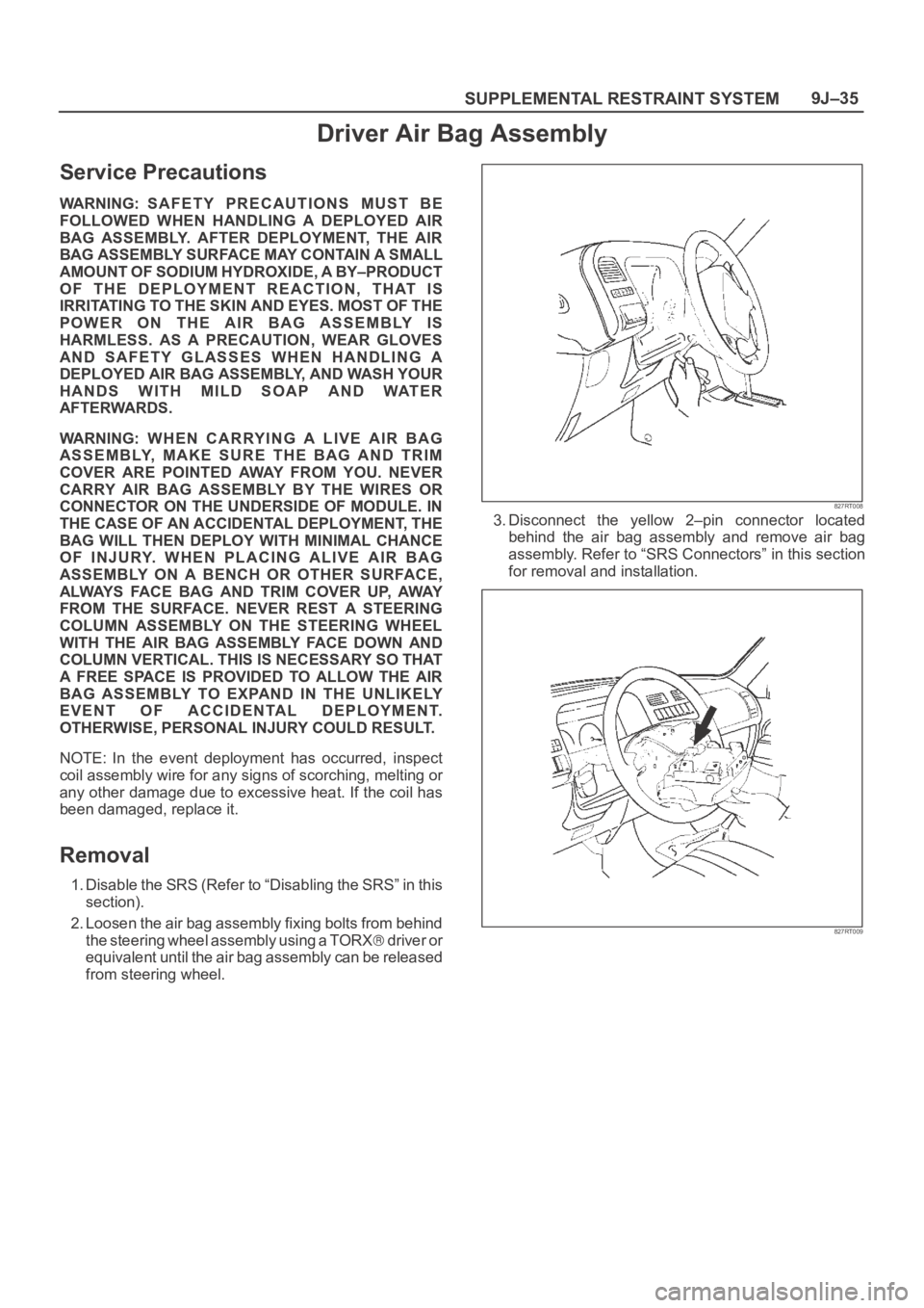
Removal
1. Disable the SRS (Refer to “Disabling the SRS” in this
section).
2. Loosen the air bag assembly fixing bolts from behind
the steering wheel assembly using a TORX
d r i v e r o r
equivalent until the air bag assembly can be released
from steering wheel.
827RT008
3. Disconnect the yellow 2–pin connector located
behind the air bag assembly and remove air bag
assembly. Refer to “SRS Connectors” in this section
for removal and installation.
827RT009
Page 3473 of 6000
SUPPLEMENTAL RESTRAINT SYSTEM 9J–36
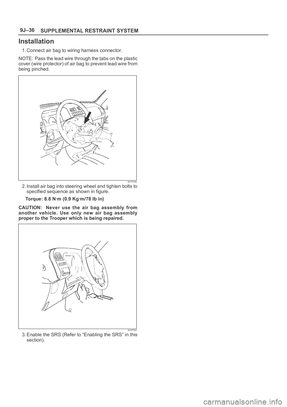
Installation
1. Connect air bag to wiring harness connector.
NOTE: Pass the lead wire through the tabs on the plastic
cover (wire protector) of air bag to prevent lead wire from
being pinched.
827RT009
2. Install air bag into steering wheel and tighten bolts to
specified sequence as shown in figure.
Torque: 8.8 Nꞏm (0.9 Kgꞏm/78 Ib in)
CAUTION: Never use the air bag assembly from
another vehicle. Use only new air bag assembly
proper to the Trooper which is being repaired.
827RT008
3. Enable the SRS (Refer to “Enabling the SRS” in this
section).