1998 OPEL FRONTERA wheel
[x] Cancel search: wheelPage 3401 of 6000
8J–22EXTERIOR/INTERIOR TRIM
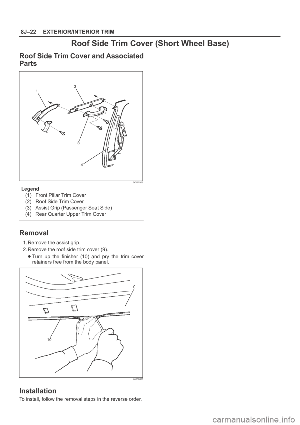
Roof Side Trim Cover (Short Wheel Base)
Roof Side Trim Cover and Associated
Parts
643RW006
Legend
(1) Front Pillar Trim Cover
(2) Roof Side Trim Cover
(3) Assist Grip (Passenger Seat Side)
(4) Rear Quarter Upper Trim Cover
Removal
1. Remove the assist grip.
2. Remove the roof side trim cover (9).
Turn up the finisher (10) and pry the trim cover
retainers free from the body panel.
643RS005
Installation
To install, follow the removal steps in the reverse order.
Page 3406 of 6000
EXTERIOR/INTERIOR TRIM8J–27
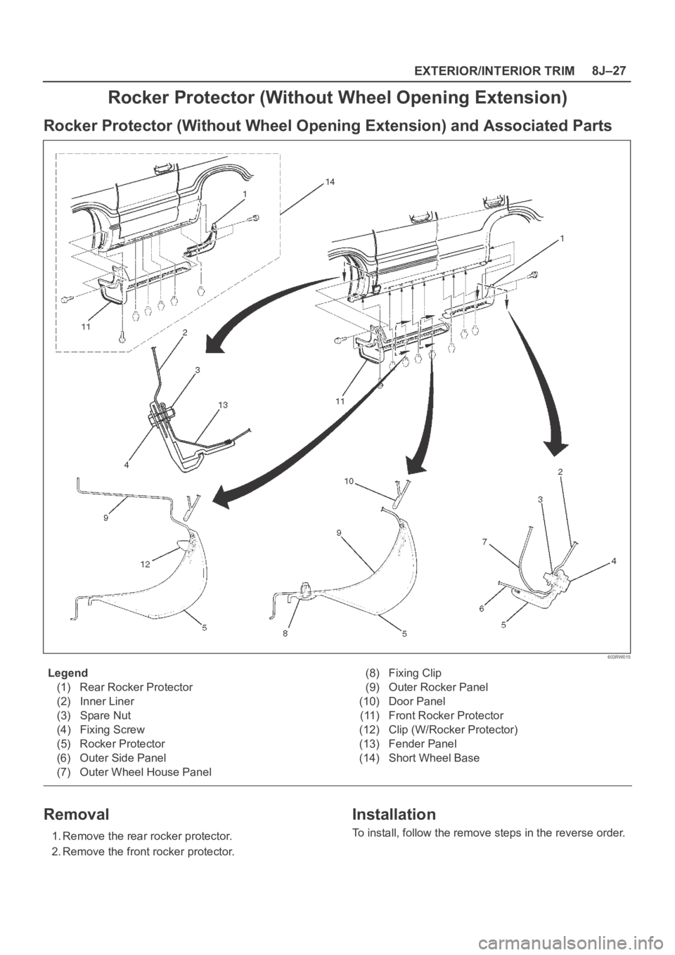
Rocker Protector (Without Wheel Opening Extension)
Rocker Protector (Without Wheel Opening Extension) and Associated Parts
603RW015
Legend
(1) Rear Rocker Protector
(2) Inner Liner
(3) Spare Nut
(4) Fixing Screw
(5) Rocker Protector
(6) Outer Side Panel
(7) Outer Wheel House Panel(8) Fixing Clip
(9) Outer Rocker Panel
(10) Door Panel
(11) Front Rocker Protector
(12) Clip (W/Rocker Protector)
(13) Fender Panel
(14) Short Wheel Base
Removal
1. Remove the rear rocker protector.
2. Remove the front rocker protector.
Installation
To install, follow the remove steps in the reverse order.
Page 3407 of 6000
8J–28EXTERIOR/INTERIOR TRIM
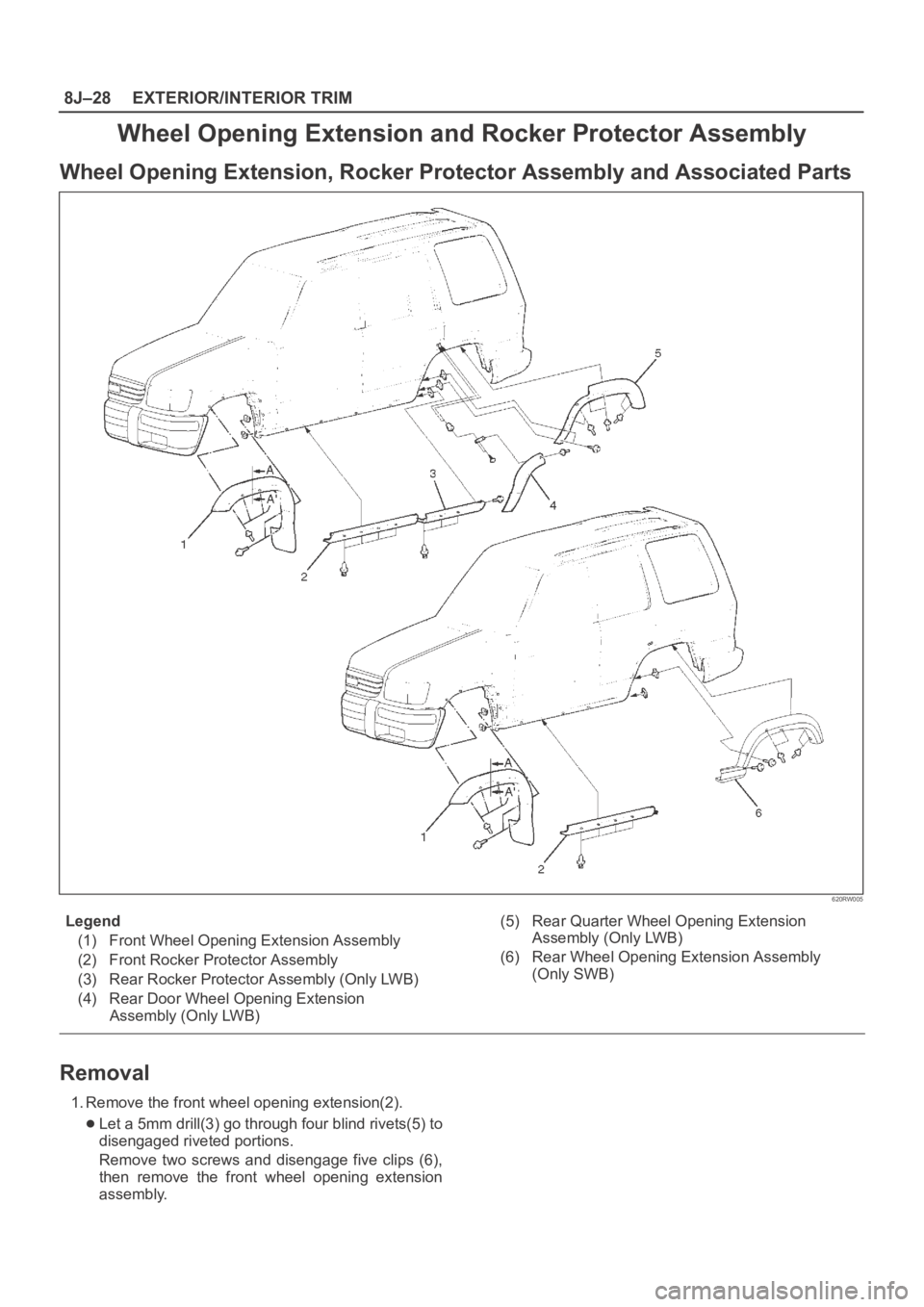
Wheel Opening Extension and Rocker Protector Assembly
Wheel Opening Extension, Rocker Protector Assembly and Associated Parts
620RW005
Legend
(1) Front Wheel Opening Extension Assembly
(2) Front Rocker Protector Assembly
(3) Rear Rocker Protector Assembly (Only LWB)
(4) Rear Door Wheel Opening Extension
Assembly (Only LWB)(5) Rear Quarter Wheel Opening Extension
Assembly (Only LWB)
(6) Rear Wheel Opening Extension Assembly
(Only SWB)
Removal
1. Remove the front wheel opening extension(2).
Let a 5mm drill(3) go through four blind rivets(5) to
disengaged riveted portions.
Remove two screws and disengage five clips (6),
then remove the front wheel opening extension
assembly.
Page 3408 of 6000
EXTERIOR/INTERIOR TRIM8J–29
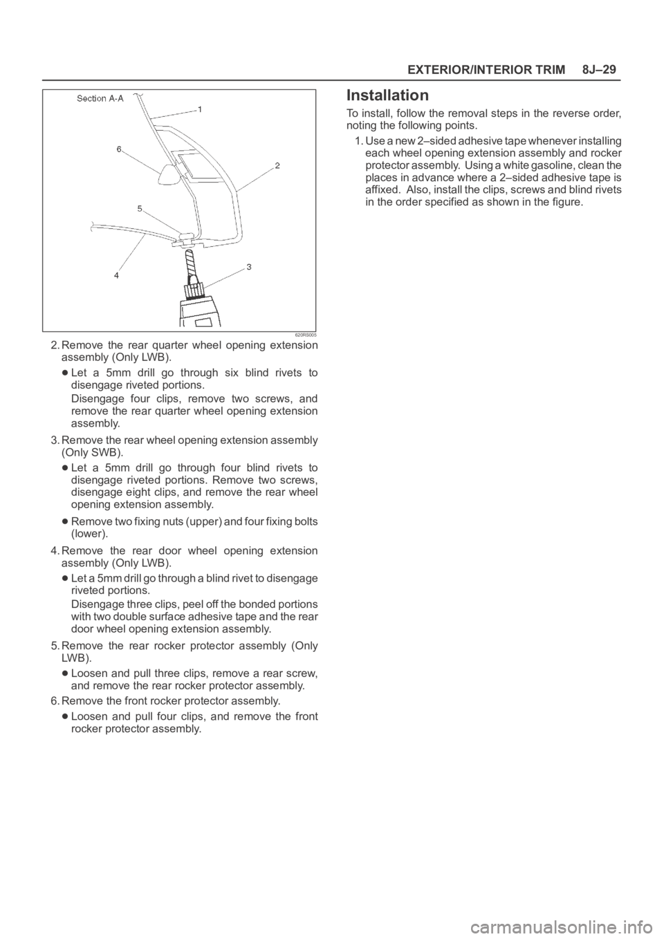
620RS005
2. Remove the rear quarter wheel opening extension
assembly (Only LWB).
Let a 5mm drill go through six blind rivets to
disengage riveted portions.
Disengage four clips, remove two screws, and
remove the rear quarter wheel opening extension
assembly.
3. Remove the rear wheel opening extension assembly
(Only SWB).
Let a 5mm drill go through four blind rivets to
disengage riveted portions. Remove two screws,
disengage eight clips, and remove the rear wheel
opening extension assembly.
Remove two fixing nuts (upper) and four fixing bolts
(lower).
4. Remove the rear door wheel opening extension
assembly (Only LWB).
Let a 5mm drill go through a blind rivet to disengage
riveted portions.
Disengage three clips, peel off the bonded portions
with two double surface adhesive tape and the rear
door wheel opening extension assembly.
5. Remove the rear rocker protector assembly (Only
LW B ) .
Loosen and pull three clips, remove a rear screw,
and remove the rear rocker protector assembly.
6. Remove the front rocker protector assembly.
Loosen and pull four clips, and remove the front
rocker protector assembly.
Installation
To install, follow the removal steps in the reverse order,
noting the following points.
1. Use a new 2–sided adhesive tape whenever installing
each wheel opening extension assembly and rocker
protector assembly. Using a white gasoline, clean the
places in advance where a 2–sided adhesive tape is
affixed. Also, install the clips, screws and blind rivets
in the order specified as shown in the figure.
Page 3410 of 6000
EXTERIOR/INTERIOR TRIM8J–31
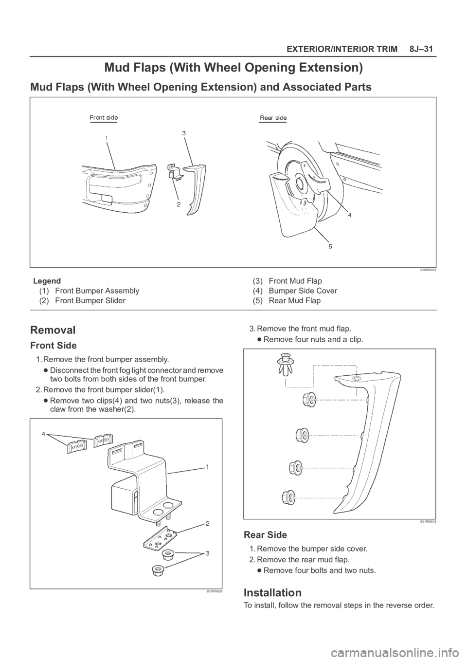
Mud Flaps (With Wheel Opening Extension)
Mud Flaps (With Wheel Opening Extension) and Associated Parts
620RW003
Legend
(1) Front Bumper Assembly
(2) Front Bumper Slider(3) Front Mud Flap
(4) Bumper Side Cover
(5) Rear Mud Flap
Removal
Front Side
1. Remove the front bumper assembly.
Disconnect the front fog light connector and remove
two bolts from both sides of the front bumper.
2. Remove the front bumper slider(1).
Remove two clips(4) and two nuts(3), release the
claw from the washer(2).
601RW009
3. Remove the front mud flap.
Remove four nuts and a clip.
601RW013
Rear Side
1. Remove the bumper side cover.
2. Remove the rear mud flap.
Remove four bolts and two nuts.
Installation
To install, follow the removal steps in the reverse order.
Page 3421 of 6000
SEAT BELT SYSTEM 9A–1
RESTRAINTS
CONTENTS
SEAT BELT SYSTEM
CONTENTS
Seat Belt System . . . . . . . . . . . . . . . . . . . . . . 9A–1
Supplemental Restraint System (SRS) . . . . . 9J–1Restraint Control System . . . . . . . . . . . . . . . . 9J1–1
Service Precaution . . . . . . . . . . . . . . . . . . . . . 9A–1
Seat Belt . . . . . . . . . . . . . . . . . . . . . . . . . . . . . 9A–2
Front Seat Belt and Associated Parts
(Long Wheel Base) . . . . . . . . . . . . . . . . . . 9A–2
Removal . . . . . . . . . . . . . . . . . . . . . . . . . . . . 9A–2
Inspection . . . . . . . . . . . . . . . . . . . . . . . . . . . 9A–2
Installation . . . . . . . . . . . . . . . . . . . . . . . . . . 9A–3
Front Seat Belt and Associated Parts
(Short Wheel Base) . . . . . . . . . . . . . . . . . . 9A–4
Removal . . . . . . . . . . . . . . . . . . . . . . . . . . . . 9A–4
Inspection . . . . . . . . . . . . . . . . . . . . . . . . . . . 9A–4
Installation . . . . . . . . . . . . . . . . . . . . . . . . . . 9A–5
Rear Seat Belt and Associated Parts
(Long Wheel Base) . . . . . . . . . . . . . . . . . . 9A–6
Removal . . . . . . . . . . . . . . . . . . . . . . . . . . . . 9A–6
Inspection . . . . . . . . . . . . . . . . . . . . . . . . . . . 9A–6
Installation . . . . . . . . . . . . . . . . . . . . . . . . . . 9A–7
Rear Seat Belt and Associated Parts
(Short Wheel Base) . . . . . . . . . . . . . . . . . . 9A–8
Removal . . . . . . . . . . . . . . . . . . . . . . . . . . . . 9A–8
Inspection . . . . . . . . . . . . . . . . . . . . . . . . . . . 9A–9
Installation . . . . . . . . . . . . . . . . . . . . . . . . . . 9A–9
Third Seat Belt and Associated Parts
(Long Wheel Base) . . . . . . . . . . . . . . . . . . 9A–10
Removal . . . . . . . . . . . . . . . . . . . . . . . . . . . . 9A–10
Inspection . . . . . . . . . . . . . . . . . . . . . . . . . . . 9A–11
Installation . . . . . . . . . . . . . . . . . . . . . . . . . . 9A–11Front Seat Buckle Assembly . . . . . . . . . . . . . 9A–12
Removal . . . . . . . . . . . . . . . . . . . . . . . . . . . . 9A–12
Installation . . . . . . . . . . . . . . . . . . . . . . . . . . 9A–12
Front Seat Buckle Assembly (W/Pretensioner) 9A–12
Removal . . . . . . . . . . . . . . . . . . . . . . . . . . . . 9A–12
Installation . . . . . . . . . . . . . . . . . . . . . . . . . . 9A–12
Rear Center Seat Belt Buckle Assembly . . . 9A–13
Rear Center Seat Belt Buckle Assembly
and Associated Parts . . . . . . . . . . . . . . . . . 9A–13
Removal . . . . . . . . . . . . . . . . . . . . . . . . . . . . 9A–13
Installation . . . . . . . . . . . . . . . . . . . . . . . . . . 9A–13
Third Seat Belt Buckle and Lock Assembly . 9A–14
Third Seat Belt Buckle and Lock Assembly
and Associated Parts . . . . . . . . . . . . . . . . . 9A–14
Removal . . . . . . . . . . . . . . . . . . . . . . . . . . . . 9A–14
Installation . . . . . . . . . . . . . . . . . . . . . . . . . . 9A–14
Rear Seat Lock Assembly . . . . . . . . . . . . . . . 9A–15
Removal . . . . . . . . . . . . . . . . . . . . . . . . . . . . 9A–15
Installation . . . . . . . . . . . . . . . . . . . . . . . . . . 9A–15
Rear Seat Lock Assembly (Bench Type) . . . 9A–15
Removal . . . . . . . . . . . . . . . . . . . . . . . . . . . . 9A–15
Installation . . . . . . . . . . . . . . . . . . . . . . . . . . 9A–15
Rear Seat Strikers . . . . . . . . . . . . . . . . . . . . . 9A–16
Removal . . . . . . . . . . . . . . . . . . . . . . . . . . . . 9A–16
Installation . . . . . . . . . . . . . . . . . . . . . . . . . . 9A–16
Third Seat Striker . . . . . . . . . . . . . . . . . . . . . . 9A–16
Removal . . . . . . . . . . . . . . . . . . . . . . . . . . . . 9A–16
Installation . . . . . . . . . . . . . . . . . . . . . . . . . . 9A–16
Main Data and Specifications . . . . . . . . . . . . 9A–17
Service Precaution
WARNING: THIS VEHICLE HAS A SUPPLEMENTAL
RESTRAINT SYSTEM (SRS). REFER TO THE SRS
COMPONENT AND WIRING LOCATION VIEW IN
ORDER TO DETERMINE WHETHER YOU ARE
PERFORMING SERVICE ON OR NEAR THE SRS
COMPONENTS OR THE SRS WIRING. WHEN YOU
ARE PERFORMING SERVICE ON OR NEAR THE SRS
COMPONENTS OR THE SRS WIRING, REFER TO
THE SRS SERVICE INFORMATION. FAILURE TO
FOLLOW WARNINGS COULD RESULT IN POSSIBLE
AIR BAG DEPLOYMENT, PERSONAL INJURY, OR
OTHERWISE UNNEEDED SRS SYSTEM REPAIRS.CAUTION: Always use the correct fastener in the
proper location. When you replace a fastener, use
ONLY the exact part number for that application.
ISUZU will call out those fasteners that require a
replacement after removal. ISUZU will also call out
the fasteners that require thread lockers or thread
sealant. UNLESS OTHERWISE SPECIFIED, do not
use supplemental coatings (Paints, greases, or other
corrosion inhibitors) on threaded fasteners or
fasteners joint interfaces. Generally, such coatings
adversely affect the fastener torque and the joint
clamping force, and may damage the fasteners.
When you install fasteners, use the correct tightening
sequence and specifications. Following these
instructions can help you avoid damage to parts and
systems.
Page 3422 of 6000
9A–2 SEAT BELT SYSTEM
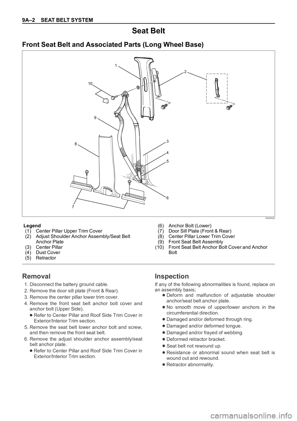
Legend
(1) Center Pillar Upper Trim Cover
(2) Adjust Shoulder Anchor Assembly/Seat Belt
Anchor Plate
(3) Center Pillar
(4) Dust Cover
(5) Retractor(6) Anchor Bolt (Lower)
(7) Door Sill Plate (Front & Rear)
(8) Center Pillar Lower Trim Cover
(9) Front Seat Belt Assembly
(10) Front Seat Belt Anchor Bolt Cover and Anchor
Bolt
Seat Belt
Front Seat Belt and Associated Parts (Long Wheel Base)
73
4
5
6 1
2
10
8
9
760RW022
Removal
1. Disconnect the battery ground cable.
2. Remove the door sill plate (Front & Rear).
3. Remove the center pillar lower trim cover.
4. Remove the front seat belt anchor bolt cover and
anchor bolt (Upper Side).
Refer to Center Pillar and Roof Side Trim Cover in
Exterior/Interior Trim section.
5. Remove the seat belt lower anchor bolt and screw,
and then remove the front seat belt.
6. Remove the adjust shoulder anchor assembly/seat
belt anchor plate.
Refer to Center Pillar and Roof Side Trim Cover in
Exterior/Interior Trim section.
Inspection
If any of the following abnormalities is found, replace on
an assembly basis;
Deform and malfunction of adjustable shoulder
anchor/seat belt anchor plate.
No smooth move of upper/lower anchors in the
circumferential direction.
Damaged and/or deformed through ring.
Damaged and/or deformed tongue.
Damaged and/or frayed of webbing.
Deformed retractor bracket.
Seat belt not rewound up.
Resistance or abnormal sound when seat belt is
wound out and rewound.
Retractor abnormality.
Page 3424 of 6000
9A–4 SEAT BELT SYSTEM
760RW024
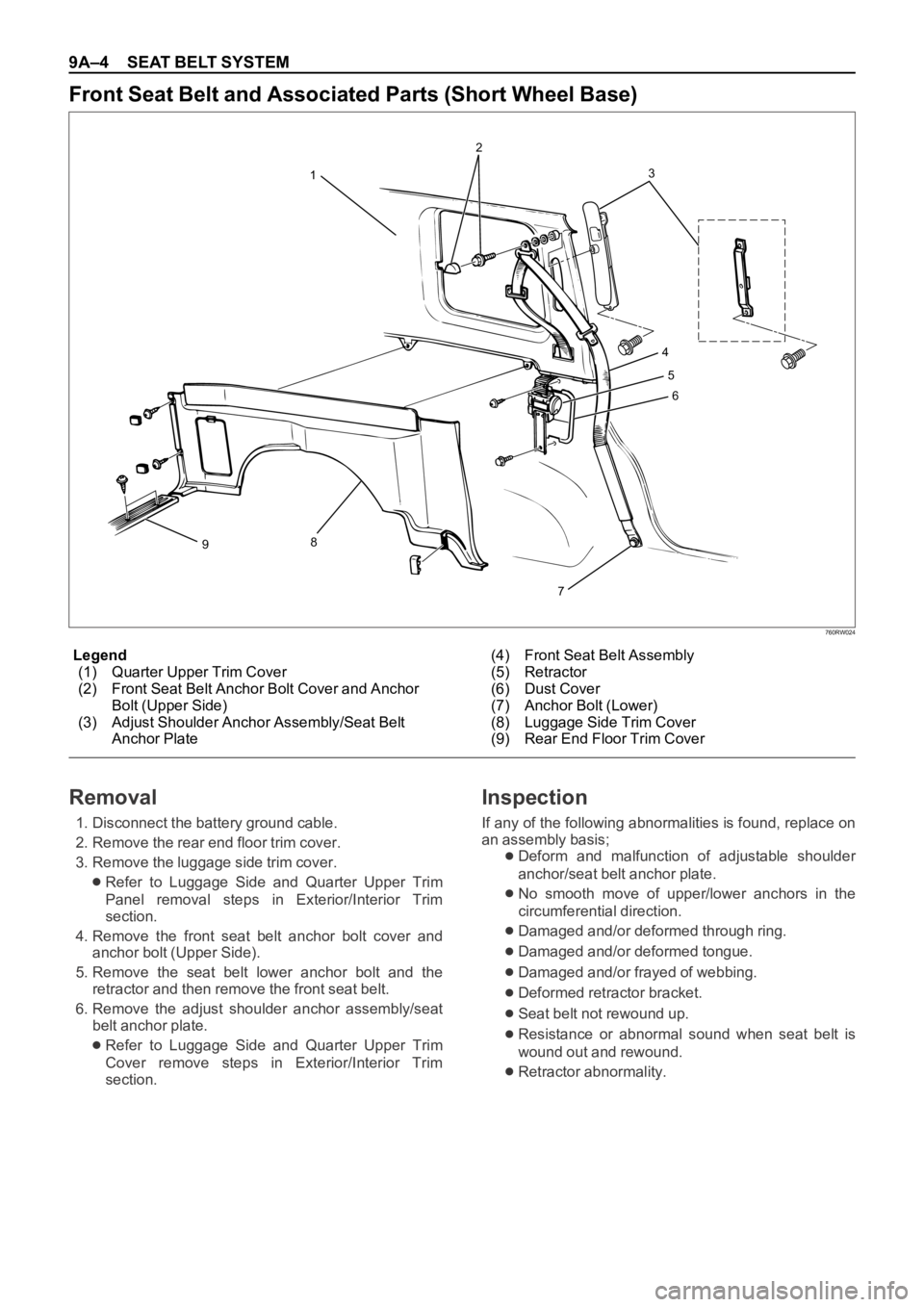
Legend
(1) Quarter Upper Trim Cover
(2) Front Seat Belt Anchor Bolt Cover and Anchor
Bolt (Upper Side)
(3) Adjust Shoulder Anchor Assembly/Seat Belt
Anchor Plate(4) Front Seat Belt Assembly
(5) Retractor
(6) Dust Cover
(7) Anchor Bolt (Lower)
(8) Luggage Side Trim Cover
(9) Rear End Floor Trim Cover
Front Seat Belt and Associated Parts (Short Wheel Base)
3
4
5
6
7
8
912
Removal
1. Disconnect the battery ground cable.
2. Remove the rear end floor trim cover.
3. Remove the luggage side trim cover.
Refer to Luggage Side and Quarter Upper Trim
Panel removal steps in Exterior/Interior Trim
section.
4. Remove the front seat belt anchor bolt cover and
anchor bolt (Upper Side).
5. Remove the seat belt lower anchor bolt and the
retractor and then remove the front seat belt.
6. Remove the adjust shoulder anchor assembly/seat
belt anchor plate.
Refer to Luggage Side and Quarter Upper Trim
Cover remove steps in Exterior/Interior Trim
section.
Inspection
If any of the following abnormalities is found, replace on
an assembly basis;
Deform and malfunction of adjustable shoulder
anchor/seat belt anchor plate.
No smooth move of upper/lower anchors in the
circumferential direction.
Damaged and/or deformed through ring.
Damaged and/or deformed tongue.
Damaged and/or frayed of webbing.
Deformed retractor bracket.
Seat belt not rewound up.
Resistance or abnormal sound when seat belt is
wound out and rewound.
Retractor abnormality.