Page 2245 of 6000
7A–91 AUTOMATIC TRANSMISSION (4L30–E)
(646) Gear Assembly, Input Sun
(647) Race Assembly, Sprag
(648) Ring, Retaining/Sprag
(649) Ring, Retaining
(650) Cage Assembly, Sprag
(651) Bearing, Output Shaft/Input Sun
(652) Washer, Output Shaft/Input Sun
(653) Carrier Assembly, Planetary(658) Gear, Reaction Sun
(659) Drum, Reaction Sun
(664) Band Assembly, Brake
(667) Seal, Ring/Wheel Parking Lock
(668) Wheel, Parking Lock
(672) Wheel, Speed
(673) Ring, Retaining
(675) Bearing, Thrust Assembly
Center Support Assembly
241RS010
Legend
(701) Center Support
(702) Retainer Plate(703) Plug, Lockout
(704) Spring, Overrun Lockout
(705) Valve, Overrun Lockout
Page 2291 of 6000

7A1–46
TRANSMISSION CONTROL SYSTEM (4L30–E)
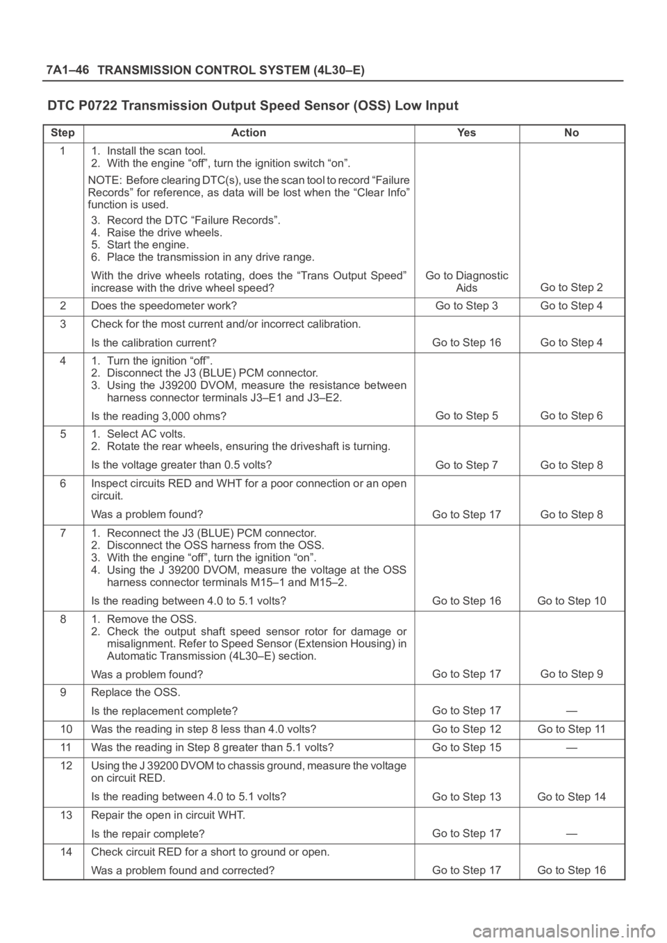
DTC P0722 Transmission Output Speed Sensor (OSS) Low Input
StepActionYe sNo
11. Install the scan tool.
2. With the engine “off”, turn the ignition switch “on”.
NOTE: Before clearing DTC(s), use the scan tool to record “Failure
Records” for reference, as data will be lost when the “Clear Info”
function is used.
3. Record the DTC “Failure Records”.
4. Raise the drive wheels.
5. Start the engine.
6. Place the transmission in any drive range.
With the drive wheels rotating, does the “Trans Output Speed”
increase with the drive wheel speed?
Go to Diagnostic
Aids
Go to Step 2
2Does the speedometer work?Go to Step 3Go to Step 4
3Check for the most current and/or incorrect calibration.
Is the calibration current?
Go to Step 16Go to Step 4
41. Turn the ignition “off”.
2. Disconnect the J3 (BLUE) PCM connector.
3. Using the J39200 DVOM, measure the resistance between
harness connector terminals J3–E1 and J3–E2.
Is the reading 3,000 ohms?
Go to Step 5Go to Step 6
51. Select AC volts.
2. Rotate the rear wheels, ensuring the driveshaft is turning.
Is the voltage greater than 0.5 volts?
Go to Step 7Go to Step 8
6Inspect circuits RED and WHT for a poor connection or an open
circuit.
Was a problem found?
Go to Step 17Go to Step 8
71. Reconnect the J3 (BLUE) PCM connector.
2. Disconnect the OSS harness from the OSS.
3. With the engine “off”, turn the ignition “on”.
4. Using the J 39200 DVOM, measure the voltage at the OSS
harness connector terminals M15–1 and M15–2.
Is the reading between 4.0 to 5.1 volts?
Go to Step 16Go to Step 10
81. Remove the OSS.
2. Check the output shaft speed sensor rotor for damage or
misalignment. Refer to Speed Sensor (Extension Housing) in
Automatic Transmission (4L30–E) section.
Was a problem found?
Go to Step 17Go to Step 9
9Replace the OSS.
Is the replacement complete?
Go to Step 17—
10Was the reading in step 8 less than 4.0 volts?Go to Step 12Go to Step 11
11Was the reading in Step 8 greater than 5.1 volts?Go to Step 15—
12Using the J 39200 DVOM to chassis ground, measure the voltage
on circuit RED.
Is the reading between 4.0 to 5.1 volts?
Go to Step 13Go to Step 14
13Repair the open in circuit WHT.
Is the repair complete?
Go to Step 17—
14Check circuit RED for a short to ground or open.
Was a problem found and corrected?
Go to Step 17Go to Step 16
Page 2294 of 6000

TRANSMISSION CONTROL SYSTEM (4L30–E)7A1–49
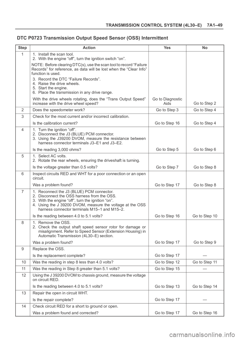
DTC P0723 Transmission Output Speed Sensor (OSS) Intermittent
StepActionYe sNo
11. Install the scan tool.
2. With the engine “off”, turn the ignition switch “on”.
NOTE: Before clearing DTC(s), use the scan tool to record “Failure
Records” for reference, as data will be lost when the “Clear Info”
function is used.
3. Record the DTC “Failure Records”.
4. Raise the drive wheels.
5. Start the engine.
6. Place the transmission in any drive range.
With the drive wheels rotating, does the “Trans Output Speed”
increase with the drive wheel speed?
Go to Diagnostic
Aids
Go to Step 2
2Does the speedometer work?Go to Step 3Go to Step 4
3Check for the most current and/or incorrect calibration.
Is the calibration current?
Go to Step 16Go to Step 4
41. Turn the ignition “off”.
2. Disconnect the J3 (BLUE) PCM connector.
3. Using the J39200 DVOM, measure the resistance between
harness connector terminals J3–E1 and J3–E2.
Is the reading 3,000 ohms?
Go to Step 5Go to Step 6
51. Select AC volts.
2. Rotate the rear wheels, ensuring the driveshaft is turning.
Is the voltage greater than 0.5 volts?
Go to Step 7Go to Step 8
6Inspect circuits RED and WHT for a poor connection or an open
circuit.
Was a problem found?
Go to Step 17Go to Step 8
71. Reconnect the J3 (BLUE) PCM connector.
2. Disconnect the OSS harness from the OSS.
3. With the engine “off”, turn the ignition “on”.
4. Using the J 39200 DVOM, measure the voltage at the OSS
harness connector terminals M15–1 and M15–2.
Is the reading between 4.0 to 5.1 volts?
Go to Step 16Go to Step 10
81. Remove the OSS.
2. Check the output shaft speed sensor rotor for damage or
misalignment. Refer to Speed Sensor (Extension Housing) in
Automatic Transmission (4L30–E) section.
Was a problem found?
Go to Step 17Go to Step 9
9Replace the OSS.
Is the replacement complete?
Go to Step 17—
10Was the reading in step 8 less than 4.0 volts?Go to Step 12Go to Step 11
11Was the reading in Step 8 greater than 5.1 volts?Go to Step 15—
12Using the J 39200 DVOM to chassis ground, measure the voltage
on circuit RED.
Is the reading between 4.0 to 5.1 volts?
Go to Step 13Go to Step 14
13Repair the open in circuit WHT.
Is the repair complete?
Go to Step 17—
14Check circuit RED for a short to ground or open.
Was a problem found and corrected?
Go to Step 17Go to Step 16
Page 2322 of 6000

7B–4MANUAL TRANSMISSION
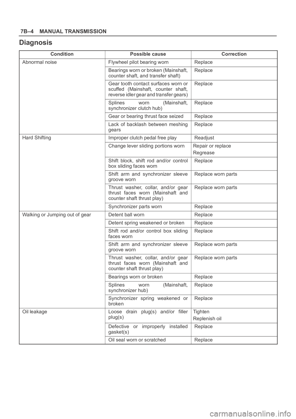
Diagnosis
ConditionPossible causeCorrection
Abnormal noiseFlywheel pilot bearing wornReplace
Bearings worn or broken (Mainshaft,
counter shaft, and transfer shaft)Replace
Gear tooth contact surfaces worn or
scuffed (Mainshaft, counter shaft,
reverse idler gear and transfer gears)Replace
Splines worn (Mainshaft,
synchronizer clutch hub)Replace
Gear or bearing thrust face seizedReplace
Lack of backlash between meshing
gearsReplace
Hard ShiftingImproper clutch pedal free playReadjust
Change lever sliding portions wornRepair or replace
Regrease
Shift block, shift rod and/or control
box sliding faces wornReplace
Shift arm and synchronizer sleeve
groove wornReplace worn parts
Thrust washer, collar, and/or gear
thrust faces worn (Mainshaft and
counter shaft thrust play)Replace worn parts
Synchronizer parts wornReplace
Walking or Jumping out of gearDetent ball wornReplace
Detent spring weakened or brokenReplace
Shift rod and/or control box sliding
faces wornReplace
Shift arm and synchronizer sleeve
groove wornReplace worn parts
Thrust washer, collar, and/or gear
thrust faces worn (Mainshaft and
counter shaft thrust play)Replace worn parts
Bearings worn or brokenReplace
Splines worn (Mainshaft,
synchronizer hub)Replace
Synchronizer spring weakened or
brokenReplace
Oil leakageLoose drain plug(s) and/or filler
plug(s)Tighten
Replenish oil
Defective or improperly installed
gasket(s)Replace
Oil seal worn or scratchedReplace
Page 2323 of 6000
MANUAL TRANSMISSION7B–5
Manual Transmission Assembly
Transmission and Associated Parts
220RW108
Legend
(1) Gear Control Lever and Knob
(2) Transfer Control Lever and Knob
(3) Front Console Assembly
(4) Grommet Assembly
(5) Transfer Protector
(6) Rear Propeller Shaft
(7) Front Propeller Shaft
(8) Exhaust Pipe
(9) Backup Lamp, 4WD Indicator, and 1–2
Indicator Switch Harness Connector
(10) Speedometer Sensor and 2WD–4WD Actuator
Harness Connector(11) Slave Cylinder Heat Protector
(12) Harness Heat Protector
(13) Slave Cylinder
(14) Dust Cover
(15) Engine Rear Mount Nut
(16) Engine Rear Mount Bolt
(17) Engine Rear Mount
(18) Third Crossmember
(19) Flywheel Under Cover
(20) Transmission Retaining Bolt
(21) Transmission Assembly with Transfer Case
Page 2327 of 6000
MANUAL TRANSMISSION7B–9
16. Remove the slave cylinder heat protector.
17. Remove the harness heat protector (6VE1).
(6VE1)
225RW006
18. Remove two transmission harness clamps and
bracket (6VE1).
19. Remove the slave cylinder.
206RW002
20. Remove the two dust cover from transmission case.
21. Support the transfer case with a jack.22. Remove two engine rear mount nuts.
(6VE1)
022RT002
23. Remove third crossmember (6VE1).
24. Remove third crossmember with rear mount rubber
(4JX1).
(4JX1)
022RW013
25. Remove two engine rear mount bolts (6VE1).
26. Remove the rear mount from the transmission
(6VE1).
27. Remove three flywheel under cover (6VE1).
Page 2331 of 6000
MANUAL TRANSMISSION7B–13
(4JX1)
225RW020
5. Apply a force of about 113N (26 Ib) to the tip of the
shift fork in the direction of the transmission to engage
the clutch pressure plate and release bearing.
NOTE: A clicking sound is heard when the release
bearing and the tip of the diaphragm spring engage each
other.
Check to see if they are securely engaged by pushing the
tip of the shift fork toward the engine while applying a
force of about 25 N (5.5 lb). If the shift fork will not move,
then they are securely engaged.
220RS006
6. Install three flywheel under cover (6VE1).
Page 2517 of 6000

7C–8CLUTCH
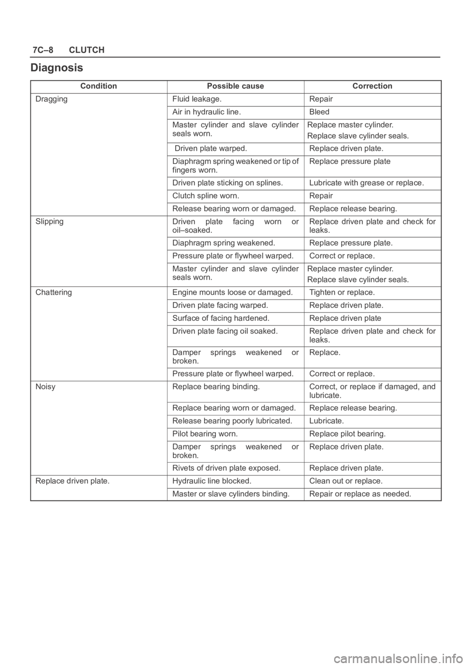
Diagnosis
ConditionPossible causeCorrection
DraggingFluid leakage.Repair
Air in hydraulic line.Bleed
Master cylinder and slave cylinder
seals worn. Replace master cylinder.
Replace slave cylinder seals.
Driven plate warped.Replace driven plate.
Diaphragm spring weakened or tip of
fingers worn. Replace pressure plate
Driven plate sticking on splines.Lubricate with grease or replace.
Clutch spline worn. Repair
Release bearing worn or damaged.Replace release bearing.
SlippingDriven plate facing worn or
oil–soaked.Replace driven plate and check for
leaks.
Diaphragm spring weakened.Replace pressure plate.
Pressure plate or flywheel warped.Correct or replace.
Master cylinder and slave cylinder
seals worn.Replace master cylinder.
Replace slave cylinder seals.
ChatteringEngine mounts loose or damaged.Tighten or replace.
Driven plate facing warped.Replace driven plate.
Surface of facing hardened.Replace driven plate
Driven plate facing oil soaked. Replace driven plate and check for
leaks.
Damper springs weakened or
broken. Replace.
Pressure plate or flywheel warped.Correct or replace.
NoisyReplace bearing binding.Correct, or replace if damaged, and
lubricate.
Replace bearing worn or damaged. Replace release bearing.
Release bearing poorly lubricated. Lubricate.
Pilot bearing worn.Replace pilot bearing.
Damper springs weakened or
broken.Replace driven plate.
Rivets of driven plate exposed.Replace driven plate.
Replace driven plate.Hydraulic line blocked.Clean out or replace.
Master or slave cylinders binding.Repair or replace as needed.