Page 1353 of 6000
6E–236
ENGINE DRIVEABILITY AND EMISSIONS
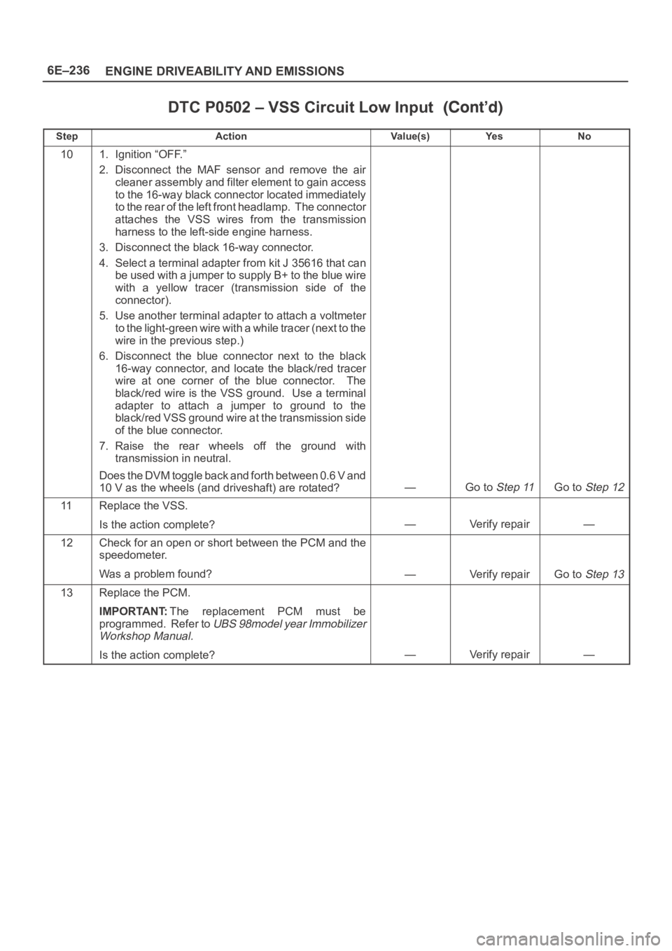
DTC P0502 – VSS Circuit Low Input
StepNo Ye s Va l u e ( s ) Action
101. Ignition “OFF.”
2. Disconnect the MAF sensor and remove the air
cleaner assembly and filter element to gain access
to the 16-way black connector located immediately
to the rear of the left front headlamp. The connector
attaches the VSS wires from the transmission
harness to the left-side engine harness.
3. Disconnect the black 16-way connector.
4. Select a terminal adapter from kit J 35616 that can
be used with a jumper to supply B+ to the blue wire
with a yellow tracer (transmission side of the
connector).
5. Use another terminal adapter to attach a voltmeter
to the light-green wire with a w h i l e t r a c e r ( n e x t t o t h e
wire in the previous step.)
6. Disconnect the blue connector next to the black
16-way connector, and locate the black/red tracer
wire at one corner of the blue connector. The
black/red wire is the VSS ground. Use a terminal
adapter to attach a jumper to ground to the
black/red VSS ground wire at the transmission side
of the blue connector.
7. Raise the rear wheels off the ground with
transmission in neutral.
Does the DVM toggle back and forth between 0.6 V and
10 V as the wheels (and driveshaft) are rotated?
—Go to Step 11Go to Step 12
11Replace the VSS.
Is the action complete?
—Verify repair—
12Check for an open or short between the PCM and the
speedometer.
Was a problem found?
—Verify repairGo to Step 13
13Replace the PCM.
IMPORTANT:The replacement PCM must be
programmed. Refer to
UBS 98model year Immobilizer
Workshop Manual.
Is the action complete?—Verify repair—
Page 1416 of 6000
6E–299 ENGINE DRIVEABILITY AND EMISSIONS
damage, therefore, it is important to use care when
handling and testing electronic components.
NOTE: To prevent possible Electrostatic Discharge
damage, follow these guidelines:
Do not touch the control module connector pins or
soldered components on the control module circuit
board.
Do not open the replacement part package until the
part is ready to be installed.
Before removing the part from the package, ground
the package to a known good ground on the vehicle.
If the part has been handled while sliding across the
seat, or while sitting down from a standing position, or
while walking a distance, touch a known good ground
before installing the part.
NOTE: To prevent internal PCM damage, the ignition
must be in the “OFF” position in order to disconnect or
reconnect power to the PCM (for example: battery cable,
PCM pigtail, PCM fuse, jumper cables, etc.).
IMPORTANT:When replacing the production PCM
with a service PCM, it is important to transfer the
broadcast code and production PCM number to the
service PCM label. This will allow positive identification of
PCM parts throughout the service life of the vehicle. Do
not record this information on the metal PCM cover.
IMPORTANT:The ignition should always be in the
“OFF” position in order to install or remove the PCM
connectors.
Service of the PCM should normally consist of either re-
placement of the PCM or EEPROM programming. If the
diagnostic procedures call for the PCM to be replaced,
the PCM should be checked first to ensure it is the correct
part. If it is, remove the faulty PCM and install the new
service PCM.
The service PCM EEPROM will not be programmed.
DTC P0601 indicates the check sum error.
Removal Procedure
1. Disconnect the negative battery cable.
2. Block the wheels.
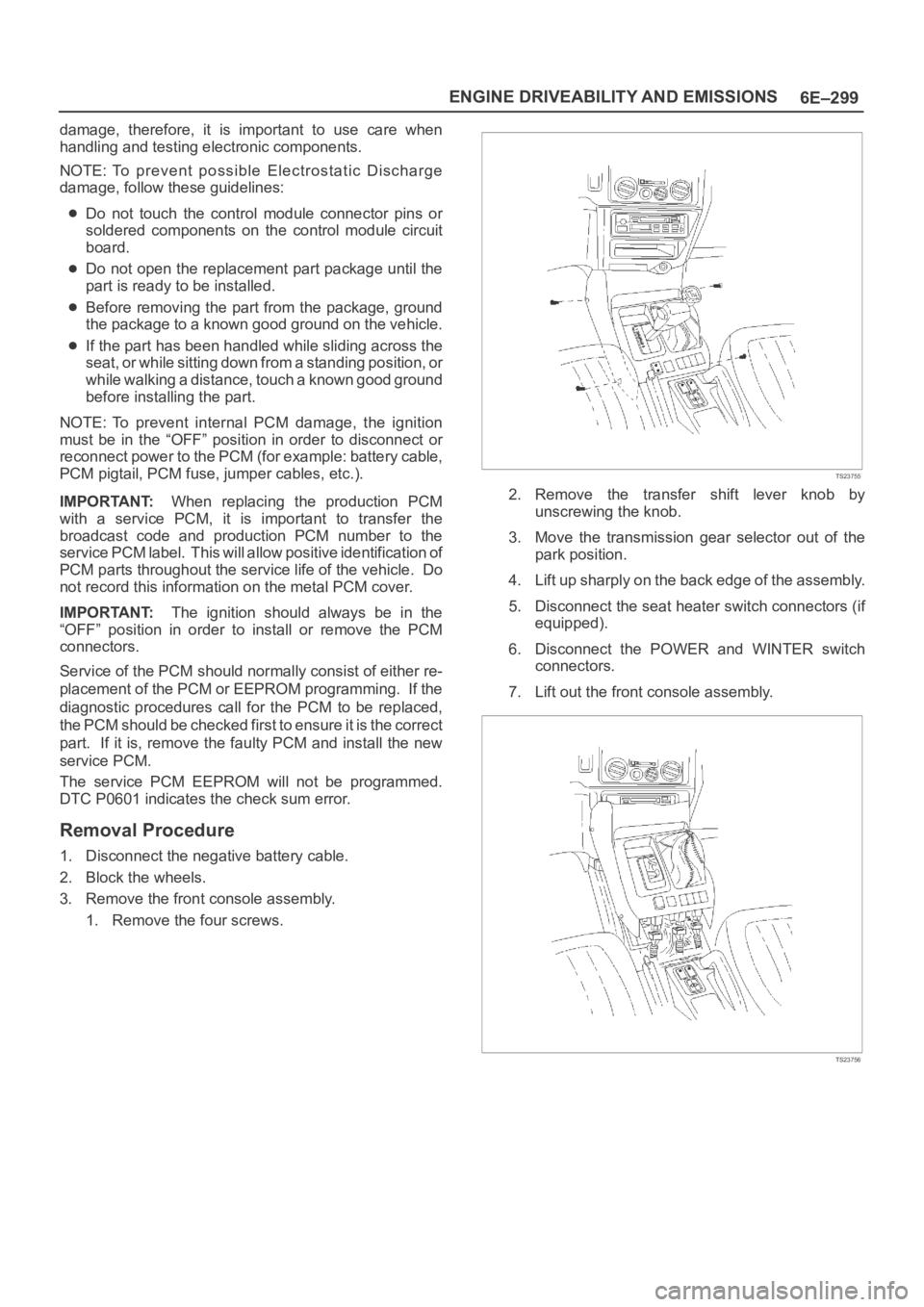
3. Remove the front console assembly.
1. Remove the four screws.
TS23755
2. Remove the transfer shift lever knob by
unscrewing the knob.
3. Move the transmission gear selector out of the
park position.
4. Lift up sharply on the back edge of the assembly.
5. Disconnect the seat heater switch connectors (if
equipped).
6. Disconnect the POWER and WINTER switch
connectors.
7. Lift out the front console assembly.
TS23756
Page 1486 of 6000
6G–7 ENGINE LUBRICATION
Oil Pan and Crankcase
Removal
1. Disconnect battery ground cable.
2. Drain engine oil.
3. Lift vehicle by supporting the frame.
4. Remove front wheels.
5. Remove oil level dipstick from level gauge tube.
6. Remove stone guard.
7. Remove radiator under fan shroud.
8. Remove suspension cross member fixing bolts, 2 pcs
each per side and remove suspension cross member.
9. Remove pitman arm and relay lever assembly, using
the 5–8840–2005–0 remover, remove pitman arm
from the steering unit and remove four fixing bolts for
relay lever assembly.
10. Remove axle housing assembly four fixing bolts from
housing isolator side and mounting bolts from wheel
side. At this time support the axle with a garage jack
and remove axle housing assembly.
11. Remove oil pan fixing bolts.
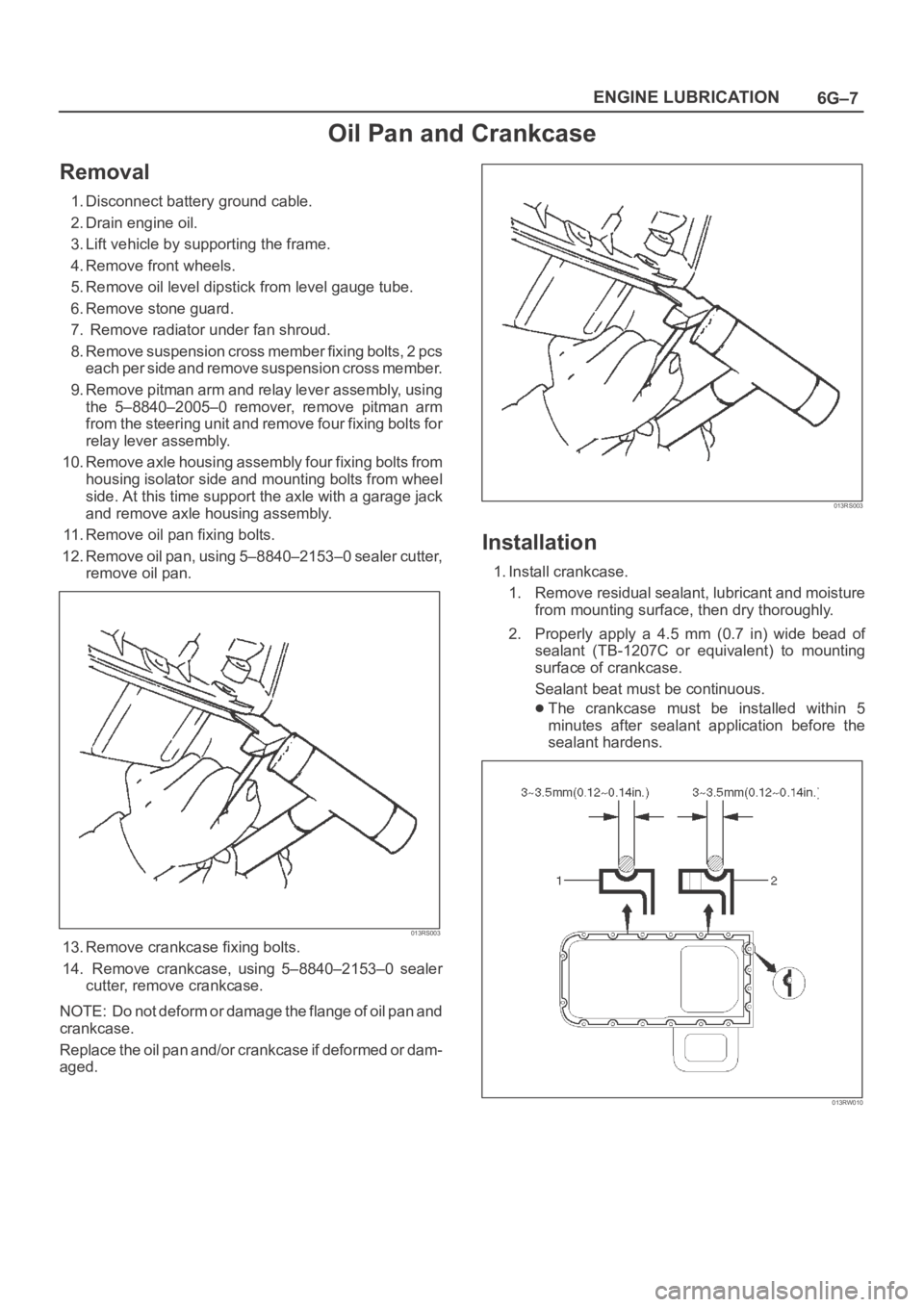
12. Remove oil pan, using 5–8840–2153–0 sealer cutter,
remove oil pan.
013RS003
13. Remove crankcase fixing bolts.
14. Remove crankcase, using 5–8840–2153–0 sealer
cutter, remove crankcase.
NOTE: Do not deform or damage the flange of oil pan and
crankcase.
Replace the oil pan and/or crankcase if deformed or dam-
aged.
013RS003
Installation
1. Install crankcase.
1. Remove residual sealant, lubricant and moisture
from mounting surface, then dry thoroughly.
2. Properly apply a 4.5 mm (0.7 in) wide bead of
sealant (TB-1207C or equivalent) to mounting
surface of crankcase.
Sealant beat must be continuous.
The crankcase must be installed within 5
minutes after sealant application before the
sealant hardens.
013RW010
Page 1735 of 6000
6A – 2 ENGINE MECHANICAL
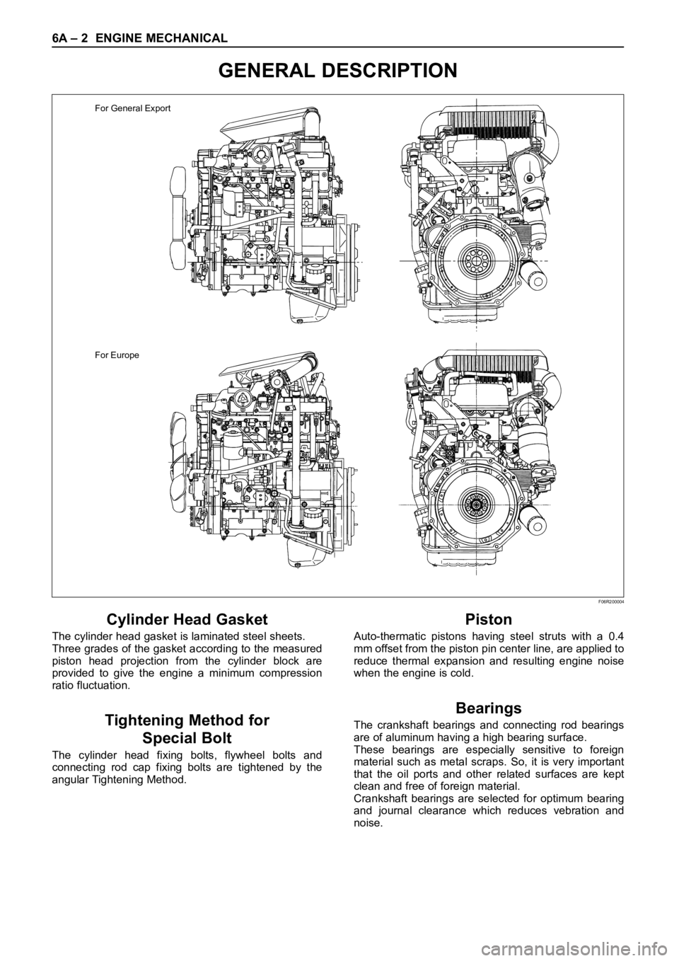
GENERAL DESCRIPTION
Cylinder Head Gasket
The cylinder head gasket is laminated steel sheets.
Three grades of the gasket according to the measured
piston head projection from the cylinder block are
provided to give the engine a minimum compression
ratio fluctuation.
Tightening Method for
Special Bolt
The cylinder head fixing bolts, flywheel bolts and
connecting rod cap fixing bolts are tightened by the
angular Tightening Method.
Piston
Auto-thermatic pistons having steel struts with a 0.4
mm offset from the piston pin center line, are applied to
reduce thermal expansion and resulting engine noise
when the engine is cold.
Bearings
The crankshaft bearings and connecting rod bearings
are of aluminum having a high bearing surface.
These bearings are especially sensitive to foreign
material such as metal scraps. So, it is very important
that the oil ports and other related surfaces are kept
clean and free of foreign material.
Crankshaft bearings are selected for optimum bearing
and journal clearance which reduces vebration and
noise.
For General Export
For Europe
F06R200004
Page 1748 of 6000
ENGINE MECHANICAL 6A – 15
Cylinder Head, Flywheel, Crank Case, Oil Pan
Nꞏm (kgꞏm/lbꞏft)
012RW121
1st
49N•m(5.0kg•m/36 Ib ft)
167(17.0/123)
8(0.8/5.8)
20(2.0/14.5)
20(2.0/14.5)
30(3.1/22)
25(2.5/18)
2nd
60
1st
59N•m(6kg•m/43 Ib ft)
2nd
60-90
1st
29N•m(3.0kg•m/22 Ib ft)
2nd
45-60
3rd
60
19(1.9/14)
Page 1805 of 6000
6A – 72 ENGINE MECHANICAL
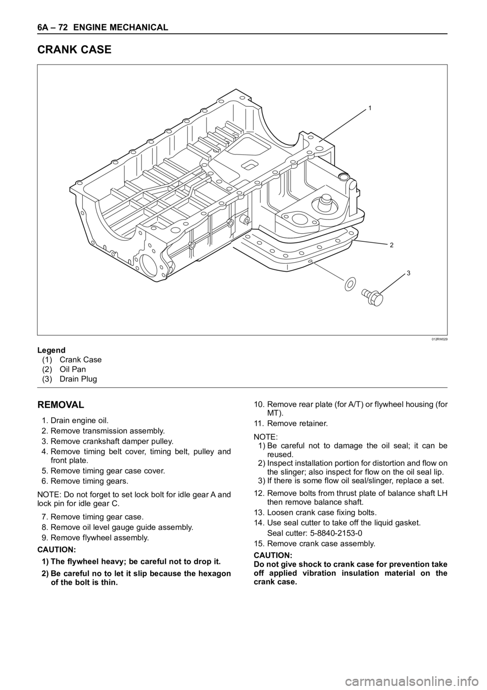
CRANK CASE
REMOVAL
1. Drain engine oil.
2. Remove transmission assembly.
3. Remove crankshaft damper pulley.
4. Remove timing belt cover, timing belt, pulley and
front plate.
5. Remove timing gear case cover.
6. Remove timing gears.
NOTE: Do not forget to set lock bolt for idle gear A and
lock pin for idle gear C.
7. Remove timing gear case.
8. Remove oil level gauge guide assembly.
9. Remove flywheel assembly.
CAUTION:
1) The flywheel heavy; be careful not to drop it.
2) Be careful no to let it slip because the hexagon
of the bolt is thin.10. Remove rear plate (for A/T) or flywheel housing (for
MT).
11. Remove retainer.
NOTE:
1) Be careful not to damage the oil seal; it can be
reused.
2) Inspect installation portion for distortion and flow on
the slinger; also inspect for flow on the oil seal lip.
3) If there is some flow oil seal/slinger, replace a set.
12. Remove bolts from thrust plate of balance shaft LH
then remove balance shaft.
13. Loosen crank case fixing bolts.
14. Use seal cutter to take off the liquid gasket.
Seal cutter: 5-8840-2153-0
15. Remove crank case assembly.
CAUTION:
Do not give shock to crank case for prevention take
off applied vibration insulation material on the
crank case.
1
2
3
012RW029
Legend
(1) Crank Case
(2) Oil Pan
(3) Drain Plug
Page 1806 of 6000
ENGINE MECHANICAL 6A – 73
INSTALLATION
1. Install relief valve (if it was removed).
Torque: 30 Nꞏm (3.1 kgꞏm / 22 lb ft)
2. Insert O-ring to strainer, install strainer and tighten
to specified torque.
Torque: 20 Nꞏm (2.0 kgꞏm / 14.5 lb ft)
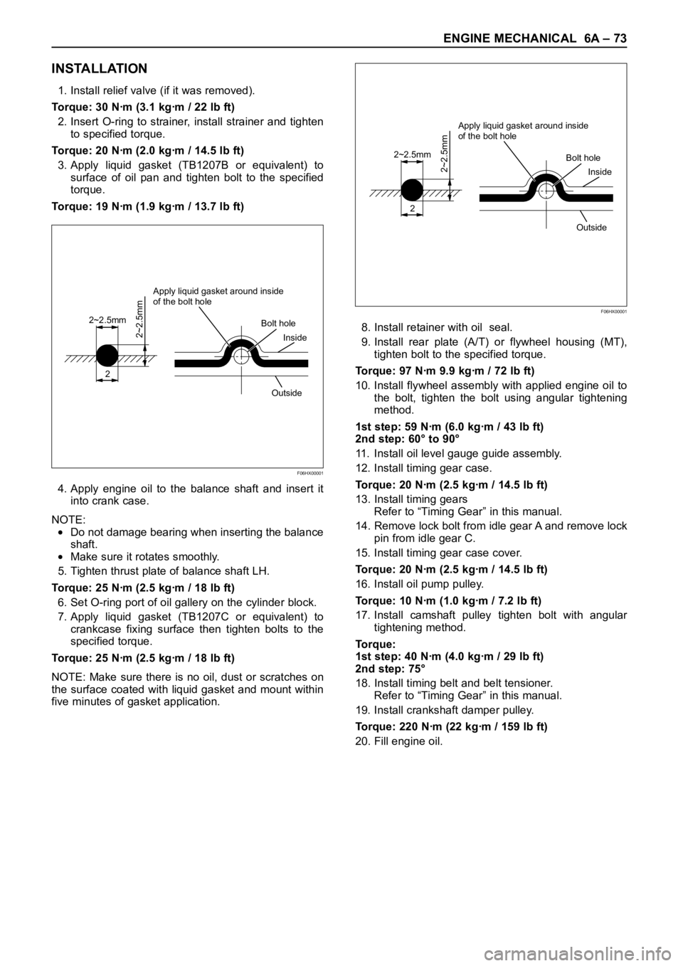
3. Apply liquid gasket (TB1207B or equivalent) to
surface of oil pan and tighten bolt to the specified
torque.
Torque: 19 Nꞏm (1.9 kgꞏm / 13.7 lb ft)
4. Apply engine oil to the balance shaft and insert it
into crank case.
NOTE:
Do not damage bearing when inserting the balance
shaft.
Make sure it rotates smoothly.
5. Tighten thrust plate of balance shaft LH.
Torque: 25 Nꞏm (2.5 kgꞏm / 18 lb ft)
6. Set O-ring port of oil gallery on the cylinder block.
7. Apply liquid gasket (TB1207C or equivalent) to
crankcase fixing surface then tighten bolts to the
specified torque.
Torque: 25 Nꞏm (2.5 kgꞏm / 18 lb ft)
NOTE: Make sure there is no oil, dust or scratches on
the surface coated with liquid gasket and mount within
five minutes of gasket application.8. Install retainer with oil seal.
9. Install rear plate (A/T) or flywheel housing (MT),
tighten bolt to the specified torque.
Torque: 97 Nꞏm 9.9 kgꞏm / 72 lb ft)
10. Install flywheel assembly with applied engine oil to
the bolt, tighten the bolt using angular tightening
method.
1st step: 59 Nꞏm (6.0 kgꞏm / 43 lb ft)
2nd step: 60° to 90°
11. Install oil level gauge guide assembly.
12. Install timing gear case.
Torque: 20 Nꞏm (2.5 kgꞏm / 14.5 lb ft)
13. Install timing gears
Refer to “Timing Gear” in this manual.
14. Remove lock bolt from idle gear A and remove lock
pin from idle gear C.
15. Install timing gear case cover.
Torque: 20 Nꞏm (2.5 kgꞏm / 14.5 lb ft)
16. Install oil pump pulley.
Torque: 10 Nꞏm (1.0 kgꞏm / 7.2 lb ft)
17. Install camshaft pulley tighten bolt with angular
tightening method.
To r q u e :
1st step: 40 Nꞏm (4.0 kgꞏm / 29 lb ft)
2nd step: 75°
18. Install timing belt and belt tensioner.
Refer to “Timing Gear” in this manual.
19. Install crankshaft damper pulley.
Torque: 220 Nꞏm (22 kgꞏm / 159 lb ft)
20. Fill engine oil.
2
2~2.5mm
2~2.5mm
Apply liquid gasket around inside
of the bolt hole
Bolt hole
Inside
Outside
F06HX00001
2
2~2.5mm
2~2.5mm
Apply liquid gasket around inside
of the bolt hole
Bolt hole
Inside
Outside
F06HX00001
Page 1807 of 6000
6A – 74 ENGINE MECHANICAL
CRANKSHAFT
1
15
14
13
8
11
16
17
10
9
72
12
3
465
18
012RW023
Legend
(1) Cylinder Head
(2) Cylinder Head Gasket
(3) Flywheel
(4) Cylinder Block Rear Plate (for A/T) or Flywheel
Housing (for M/T)
(5) Crankshaft Rear Oil Seal
(6) Retainer
(7) Timing Gear Case
(8) Crankshaft Front Oil Seal(9) Timing Gear Case
(10) Gasket
(11) Balance Shaft
(12) Crank Case
(13) Piston Cooling Oil Pipe
(14) Main Bearing Cap
(15) Crankshaft
(16) Crankshaft Timing Gear
(17) Piston and Connecting Rod Assembly
(18) Cylinder Block