Page 2382 of 6000
7B–64MANUAL TRANSMISSION
6. Check that the top gear shaft and mainshaft
rotate.
36. Install the transfer adapter.
1. Clean up the fitting surface.
2. Apply recommended liquid gasket (THREE
BOND 1281 or equivalent), as shown.
NOTE:
Don’t dry the liquid gasket.
220RW026
3. Using a plastic hammer, tap the transfer adapter
and attach it to the intermediate plate.
220RW034
4. Using 10 bolts, install the transfer adapter.
Torque: 37 Nꞏm (3.8 kgꞏm/27 lb ft)
NOTE:
Tighten the all bolts evenly.
Don’t damage the lip of the oil seal.
Install the wire clamp (9) to the transfer adapter.
220RW083
37. Install the gear control box.
1. Align the projection of the shift lever housing to
the shaft rod groove, and install the gear control
rod.
230RW003
Page 2383 of 6000
MANUAL TRANSMISSION7B–65
2. Using a pin punch and hammer, drive in the
slotted spring pin (2) to the shift lever housing.
NOTE: Be carefull not to drop the slotted spring pin.
230RW002
3. Apply sealant (THREE BOND 1344 or
equivalent) to the plug (1) thread.
4. Using hexagon wrench, install and torque the
plug (1).
Torque: 18 Nꞏm (1.8 kgꞏm/13 lb ft)
220RW010
5. Clean up the bolts and bolt hole.
6. Using 6 bolts, install the gear control box through
the gasket.
Torque 18 Nꞏm (1.8 kgꞏm/13 lb ft)
(6VE1)
230RW001
(4JX1)
220RW097
Page 2384 of 6000

7B–66MANUAL TRANSMISSION
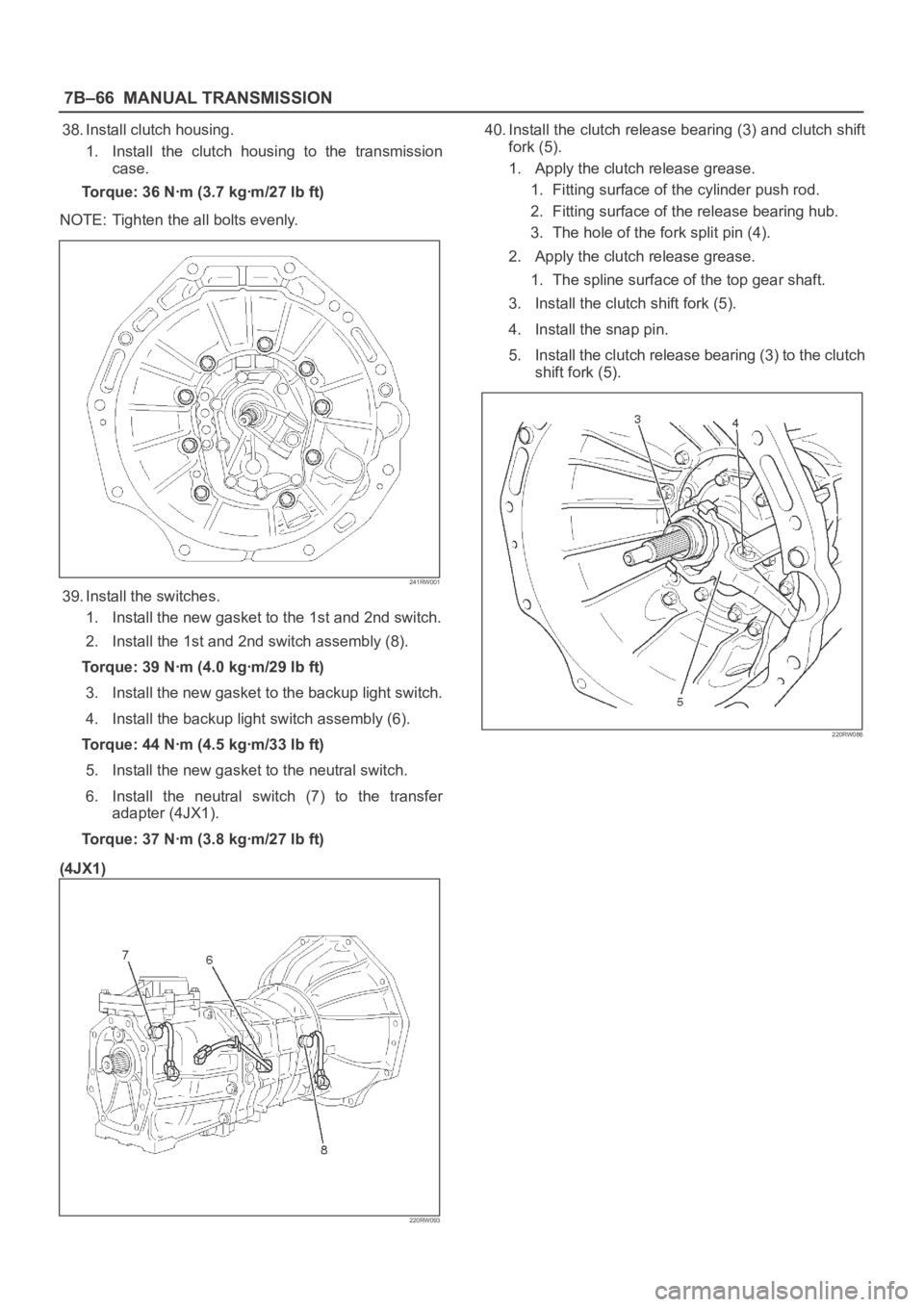
38. Install clutch housing.
1. Install the clutch housing to the transmission
case.
Torque: 36 Nꞏm (3.7 kgꞏm/27 lb ft)
NOTE: Tighten the all bolts evenly.
241RW001
39. Install the switches.
1. Install the new gasket to the 1st and 2nd switch.
2. Install the 1st and 2nd switch assembly (8).
Torque: 39 Nꞏm (4.0 kgꞏm/29 lb ft)
3. Install the new gasket to the backup light switch.
4. Install the backup light switch assembly (6).
Torque: 44 Nꞏm (4.5 kgꞏm/33 lb ft)
5. Install the new gasket to the neutral switch.
6. Install the neutral switch (7) to the transfer
adapter (4JX1).
Torque: 37 Nꞏm (3.8 kgꞏm/27 lb ft)
(4JX1)
220RW093
40. Install the clutch release bearing (3) and clutch shift
fork (5).
1. Apply the clutch release grease.
1. Fitting surface of the cylinder push rod.
2. Fitting surface of the release bearing hub.
3. The hole of the fork split pin (4).
2. Apply the clutch release grease.
1. The spline surface of the top gear shaft.
3. Install the clutch shift fork (5).
4. Install the snap pin.
5. Install the clutch release bearing (3) to the clutch
shift fork (5).
220RW086
Page 2385 of 6000
MANUAL TRANSMISSION7B–67
41. Install the drain plug and filler plug.
1. Install the drain plug (1) through the new gasket.
Torque: 37 Nꞏm (3.8 kgꞏm/27 lb ft)
2. Install the filler plug (2) through the new gasket.
Reference: Plug after the gear oil fill in.
Torque: 37 Nꞏm (3.8 kgꞏm/27 lb ft)
(6VE1)
220RW007
Page 2531 of 6000
7C–22CLUTCH
Master Cylinder
Disassembled View
208RW016
Legend
(1) Master Cylinder Assembly
(2) Gasket(3) Damper Cylinder Assembly
(4) Nut
(5) Push Rod Damper
Page 2532 of 6000
CLUTCH7C–23
Disassembly
(4JX1)
1. Remove damper cylinder assembly and gasket.
2. Remove push rod damper.
NOTE: The master cylinder assembly cannot be
disassembled because of point–staked rod stopper.
Inspection and Repair
Clean and inspect the removed parts.
Make necessary parts replacement if any abnormalities
such as wear, oil leaks or other damage are found through
inspection.
Reassembly
To reassemble, follow the disassembly steps in the
reverse order, noting the following points:
1.Push rod set length
RHD: 117.5 mm (4.626 in)
LHD: 119 mm (4.685 in)
2.Push rod nut torque
17 Nꞏm (1.7 kgꞏm/12 Ib ft)
3.Damper cylinder torque
47 Nꞏm (4.8 kgꞏm/35 Ib ft)
Page 2535 of 6000
7C–26CLUTCH
Damper Cylinder
Disassembled View
205RW005
Legend
(1) Cylinder Body
(2) Spring
(3) Piston Assembly(4) Spacer
(5) Damper Rubber
(6) Cover and Gasket
Disassembly
1. Remove cover and gasket.
2. Remove damper rubber.
3. Remove spacer.
4. Remove piston assembly.
5. Remove spring.
Inspection and Repair
Check damper rubber and piston cup for cracks,
deformation or damage.
Replace the damper cylinder assembly if necessary.
Reassembly
To assemble, follow the disassembly steps in the reverse
order.
Page 3179 of 6000
8E–2METER AND GAUGE
Meter Assembly
General Description
The meter assembly has the speedometer, tachometer,
engine coolant temperature gauge, fuel gauge and
warning/indicator lights. In addition, the meter assembly
containing TOD (Torque on Demand) has the TOD
indicator light, or the meter assembly not containing TOD
has the voltmeter and oil pressure gauge instead of the
TOD indicator.
Layout for Meters/Gauges, Warning Lights, Indicator Lights and Illumination
Lights
Meter Assembly–Gasoline W/O TOD (Front View)
825RW207
Legend
(1) Voltmeter & Engine Coolant Temperature
Gauge
(2) Tachometer
(3) Warning Light Lens
(4) Speedometer(5) Oil Pressure Gauge & Fuel Gauge
(6) Warning Light Lens
(7) Reset Knob
(8) A/T Shift Indicator
(9) Warning Light Lens