1998 OPEL FRONTERA Gas
[x] Cancel search: GasPage 3200 of 6000
8F–5 BODY STRUCTURE
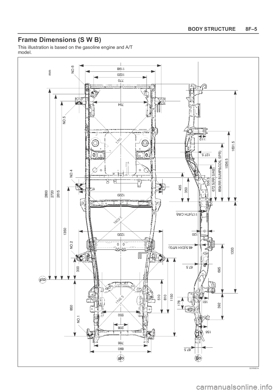
Frame Dimensions (S W B)
This illustration is based on the gasoline engine and A/T
model.
501RW014
Page 3408 of 6000
EXTERIOR/INTERIOR TRIM8J–29
620RS005
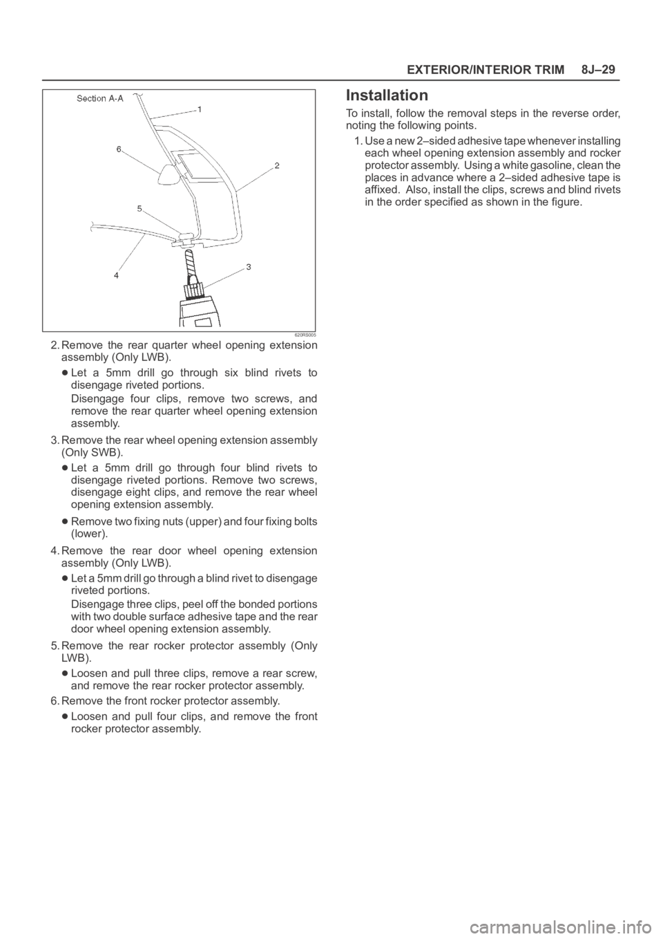
2. Remove the rear quarter wheel opening extension
assembly (Only LWB).
Let a 5mm drill go through six blind rivets to
disengage riveted portions.
Disengage four clips, remove two screws, and
remove the rear quarter wheel opening extension
assembly.
3. Remove the rear wheel opening extension assembly
(Only SWB).
Let a 5mm drill go through four blind rivets to
disengage riveted portions. Remove two screws,
disengage eight clips, and remove the rear wheel
opening extension assembly.
Remove two fixing nuts (upper) and four fixing bolts
(lower).
4. Remove the rear door wheel opening extension
assembly (Only LWB).
Let a 5mm drill go through a blind rivet to disengage
riveted portions.
Disengage three clips, peel off the bonded portions
with two double surface adhesive tape and the rear
door wheel opening extension assembly.
5. Remove the rear rocker protector assembly (Only
LW B ) .
Loosen and pull three clips, remove a rear screw,
and remove the rear rocker protector assembly.
6. Remove the front rocker protector assembly.
Loosen and pull four clips, and remove the front
rocker protector assembly.
Installation
To install, follow the removal steps in the reverse order,
noting the following points.
1. Use a new 2–sided adhesive tape whenever installing
each wheel opening extension assembly and rocker
protector assembly. Using a white gasoline, clean the
places in advance where a 2–sided adhesive tape is
affixed. Also, install the clips, screws and blind rivets
in the order specified as shown in the figure.
Page 3443 of 6000
SUPPLEMENTAL RESTRAINT SYSTEM 9J–6
825RS017
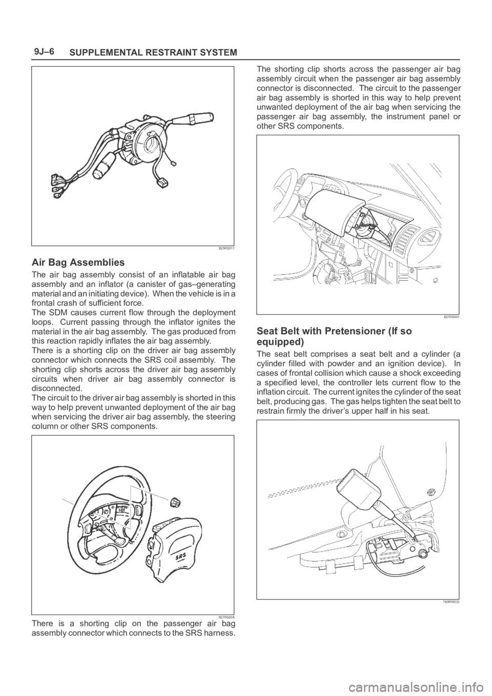
Air Bag Assemblies
The air bag assembly consist of an inflatable air bag
assembly and an inflator (a canister of gas–generating
material and an initiating device). When the vehicle is in a
frontal crash of sufficient force.
The SDM causes current flow through the deployment
loops. Current passing through the inflator ignites the
material in the air bag assembly. The gas produced from
this reaction rapidly inflates the air bag assembly.
There is a shorting clip on the driver air bag assembly
connector which connects the SRS coil assembly. The
shorting clip shorts across the driver air bag assembly
circuits when driver air bag assembly connector is
disconnected.
The circuit to the driver air bag assembly is shorted in this
way to help prevent unwanted deployment of the air bag
when servicing the driver air bag assembly, the steering
column or other SRS components.
827RS008There is a shorting clip on the passenger air bag
assembly connector which connects to the SRS harness.The shorting clip shorts across the passenger air bag
assembly circuit when the passenger air bag assembly
connector is disconnected. The circuit to the passenger
air bag assembly is shorted in this way to help prevent
unwanted deployment of the air bag when servicing the
passenger air bag assembly, the instrument panel or
other SRS components.
827RS001
Seat Belt with Pretensioner (If so
equipped)
The seat belt comprises a seat belt and a cylinder (a
cylinder filled with powder and an ignition device). In
cases of frontal collision which cause a shock exceeding
a specified level, the controller lets current flow to the
inflation circuit. The current ignites the cylinder of the seat
belt, producing gas. The gas helps tighten the seat belt to
restrain firmly the driver’s upper half in his seat.
760RW033
Page 3448 of 6000
SUPPLEMENTAL RESTRAINT SYSTEM9J–11
Handling / Installation / Diagnosis
1. Air bag assembly should not be subjected to
temperatures above 93
C (200F).
2. Air bag assembly, and SDM should not be used if they
have been dropped from a height of 100 centimeters
(3.28 feet) or more.
3. When a SDM is replaced, it must be oriented with the
arrow on the sensor pointing toward the front of the
vehicle. It is very important for the SDM to be located
flat on the mounting surface, parallel to the vehicle
datum line. It is important that the SDM mounting
surface is free of any dirt or other foreign material.
4. Do not apply power to the SRS unless all components
are connected or a diagnostic chart requests it, as this
will set a diagnostic trouble code.
5. The “SRS Diagnostic System Check” must be the
starting point of any SRS diagnostics. The “SRS
Diagnostic System Check” will verify proper “AIR
BAG” warning lamp operation and will lead you to the
correct chart to diagnose any SRS malfunctions.
Bypassing these procedures may result in extended
diagnostic time, incorrect diagnosis, and incorrect
parts replacement.
Air Bag Assembly Handling /
Shipping / Scrapping
Live (Undeployed) Air Bag Assembly
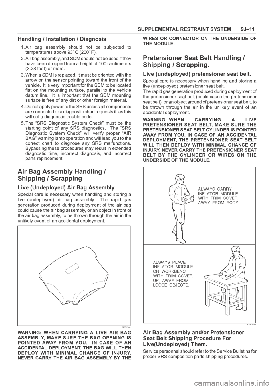
Special care is necessary when handling and storing a
live (undeployed) air bag assembly. The rapid gas
generation produced during deployment of the air bag
could cause the air bag assembly, or an object in front of
the air bag assembly, to be thrown through the air in the
unlikely event of an accidental deployment.
827RV004
WARNING: WHEN CARRYING A LIVE AIR BAG
ASSEMBLY, MAKE SURE THE BAG OPENING IS
POINTED AWAY FROM YOU. IN CASE OF AN
ACCIDENTAL DEPLOYMENT, THE BAG WILL THEN
DEPLOY WITH MINIMAL CHANCE OF INJURY.
NEVER CARRY THE AIR BAG ASSEMBLY BY THEWIRES OR CONNECTOR ON THE UNDERSIDE OF
THE MODULE.
Pretensioner Seat Belt Handling /
Shipping / Scrapping.
Live (undeployed) pretensioner seat belt.
Special care is necessary when handling and storing a
live (undeployed) pretensioner seat belt.
The rapid gas generation produced during deployment of
the pretensioner seat belt (could cause the pretensioner
seat belt), or an object around of pretensioner seat belt, to
be thrown through the air in the unlikely event of an
accidental deployment.
WARNING: WHEN CARRYING A LIVE
PRETENSIONER SEAT BELT, MAKE SURE THE
PRETENSIONER SEAT BELT CYLINDER IS POINTED
AWAY FROM YOU. IN CASE OF AN ACCIDENTAL
DEPLOYMENT, THE PRETENSIONER SEAT BELT
WILL THEN DEPLOY WITH MINIMAL CHANCE OF
INJURY. NEVER CARRY THE PRETENSIONER SEAT
BELT BY THE CYLINDER OR WIRES ON THE
UNDERSIDE OF THE MODULE.
827RS044
Air Bag Assembly and/or Pretensioner
Seat Belt Shipping Procedure For
Live(Undeployed) Them.
Service personnel should refer to the Service Bulletins for
proper SRS composition parts shipping procedures.
Page 3451 of 6000
SUPPLEMENTAL RESTRAINT SYSTEM 9J–14
10. Place a power source near the shorted end of the
SRS deployment harness. Recommended
application: 12 volts minimum, 2 amps minimum. A
vehicle battery is suggested.
11. Connect the driver air bag assembly to the pigtail
adapter on the SRS deployment harness.
Deployment harness shall remain shorted and not be
connected to a power source until the air bag is to be
deployed. The driver air bag assembly will
immediately deploy the air bag when a power source
is connected to it.
NOTE: Ensure that the pigtail adapter is firmly seated into
the driver air bag assembly connector. Failure to fully
seat the connectors may leave the shorting bar located in
the driver air bag assembly connector functioning
(shorted) and may result in nondeployment of the driver
air bag assembly.
12. Verify that the area around the driver air bag
assembly is clear of all people and loose or flammable
objects.
13. Verify that the driver air bag assembly is resting with
its trim cover facing up.
14. Notify all people in the immediate area that you intend
to deploy the driver air bag. The deployment will be
accompanied by a substantial noise which may
startle the uninformed.
15. Separate the two banana plugs on the SRS
deployment harness.
NOTE: When the air bag deploys, the driver air bag
assembly may jump about 3 m (ten feet) vertically. This
is a normal reaction of the driver air bag to the force of the
rapid gas expansion inside the air bag.
NOTE: When the air bag deploys, the rapid gas
expansion will create a substantial noise. Notify all
people in the immediate area that you intend to deploy the
driver air bag.
WARNING: DEPLOYMENT HARNESS SHALL
REMAIN SHORTED AND NOT BE CONNECTED TO A
POWER SOURCE UNTIL THE AIR BAG IS TO BE
DEPLOYED. THE AIR BAG ASSEMBLY WILL
IMMEDIATELY DEPLOY THE AIR BAG WHEN A
POWER SOURCE IS CONNECTED TO IT.
CONNECTING THE DEPLOYMENT HARNESS TO
THE POWER SOURCE SHOULD ALWAYS BE THE
LAST STEP IN THE AIR BAG ASSEMBLY
DEPLOYMENT PROCEDURE. FAILURE TO FOLLOW
PROCEDURES IN THE ORDER LISTED MAY RESULT
IN PERSONAL INJURY.
16. Connect the SRS deployment harness wires to the
power source to immediately deploy the driver air
bag. Recommended application: 12 volts minimum, 2
amps minimum. A vehicle battery is suggested.
17. Disconnect the SRS deployment harness from the
power source.
18. Short the two SRS deployment harness leads
together by fully seating one banana plug into the
other.19. In the unlikely event that the driver air bag assembly
did not deploy after following these procedures,
proceed immediately with Steps 24 through 26. If the
driver air bag assembly did deploy, proceed with
Steps 20 through 23.
20. Put on a pair of shop gloves and safety glasses to
protect your hands and eyes from possible irritation
and heat when handling the deployed driver air bag
assembly. After the air bag assembly has been
deployed, the surface of the air bag may contain a
powdery residue. This solid particulate consists
primarily of by products of the chemical reaction,
Potassium Chloride and copper metal dust.
Compounds of Potassium Borate, Strontium
Chloride, Copper Chloride, and Ammonium Chloride
may be found in amounts of about 1 % (each) of the
total particulate.
WARNING: SAFETY PRECAUTIONS MUST BE
OBSERVED WHEN HANDING A DEPLOYED AIR BAG
ASSEMBLY. AFTER DEPLOYMENT, THE METAL
SURFACES OF THE AIR BAG ASSEMBLY WILL BE
VERY HOT. ALLOW THE INFLATOR MODULE TO
COOL BEFORE HANDLING ANY METAL PORTION
OF IT. DO NOT PLACE THE DEPLOYED AIR BAG
ASSEMBLY NEAR ANY FLAMMABLE OBJECTS.
FAILURE TO FOLLOW PROCEDURES MAY RESULT
IN FIRE OR PERSONAL INJURY.
AFTER A DRIVER AIR BAG ASSEMBLY HAS BEEN
DEPLOYED, THE METAL CANISTER AND
SURROUNDING AREAS OF THE DRIVER AIR BAG
ASSEMBLY WILL BE VERY HOT. DO NOT TOUCH
THE METAL AREAS OF THE DRIVER AIR BAG
ASSEMBLY FOR ABOUT TEN MINUTES AFTER
DEPLOYMENT. IF THE DEPLOYED DRIVER AIR BAG
ASSEMBLY MUST BE MOVED BEFORE IT IS COOL,
WEAR GLOVES AND HANDLE BY THE AIR BAG OR
TRIM COVER.
21. Disconnect the pigtail adapter from the driver air bag
assembly as soon after deployment as possible. This
will prevent damage to the pigtail adapter or SRS
deployment harness due to possible contact with the
hot driver air bag assembly canister. The pigtail
adapter can be reused. They should, however, be
inspected for damage after each deployment and
replaced if necessary.
22. Dispose of the deployed driver air bag assembly
through normal refuse channels after it has cooled for
at least 30 minutes.
23. Wash your hands with mild soap and water afterward.
NOTE: The remaining steps are to be followed in the
unlikely event that the driver air bag assembly did not
deploy after following these procedures.
24. Ensure that the SRS deployment harness has been
disconnected from the power source and that its two
banana plugs have been shorted together by fully
seating one banana plug into the other.
25. Disconnect the pigtail adapter from the driver air bag
assembly.
WARNING: W H E N S T O R I N G A L I V E A I R B A G
ASSEMBLY OR WHEN LEAVING A LIVE INFLATOR
MODULE UNATTENDED ON A BENCH OR OTHER
Page 3453 of 6000
SUPPLEMENTAL RESTRAINT SYSTEM 9J–16
5. Remove passenger air bag assembly from vehicle.
Refer to “Passenger Air Bag Assembly Removal ” in
this Section 9J–3.
6. Clear a space on the ground approximately 183 cm
(six feet) in clearance where the fixture with attached
air bag assembly is to be placed for deployment. A
paved outdoor location where there is no activity is
preferred. If an outdoor location is not available, a
space on the shop floor where is no activity and
sufficient ventilation is recommended. Ensure that no
loose or flammable objects are within the deployment
area.
7. Place the 5–8840–2420–0 on the bench vice. This is
necessary to provide sufficient stabilization of the
fixture during deployment.
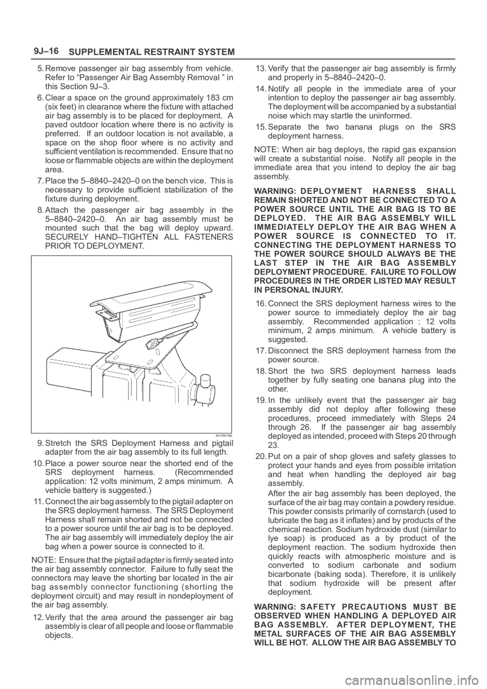
8. Attach the passenger air bag assembly in the
5–8840–2420–0. An air bag assembly must be
mounted such that the bag will deploy upward.
SECURELY HAND–TIGHTEN ALL FASTENERS
PRIOR TO DEPLOYMENT.
901RW199
9. Stretch the SRS Deployment Harness and pigtail
adapter from the air bag assembly to its full length.
10. Place a power source near the shorted end of the
SRS deployment harness. (Recommended
application: 12 volts minimum, 2 amps minimum. A
vehicle battery is suggested.)
11. Connect the air bag assembly to the pigtail adapter on
the SRS deployment harness. The SRS Deployment
Harness shall remain shorted and not be connected
to a power source until the air bag is to be deployed.
The air bag assembly will immediately deploy the air
bag when a power source is connected to it.
NOTE: Ensure that the pigtail adapter is firmly seated into
the air bag assembly connector. Failure to fully seat the
connectors may leave the shorting bar located in the air
bag assembly connector functioning (shorting the
deployment circuit) and may result in nondeployment of
the air bag assembly.
12. Verify that the area around the passenger air bag
assembly is clear of all people and loose or flammable
objects.13. Verify that the passenger air bag assembly is firmly
and properly in 5–8840–2420–0.
14. Notify all people in the immediate area of your
intention to deploy the passenger air bag assembly.
The deployment will be accompanied by a substantial
noise which may startle the uninformed.
15. Separate the two banana plugs on the SRS
deployment harness.
NOTE: When air bag deploys, the rapid gas expansion
will create a substantial noise. Notify all people in the
immediate area that you intend to deploy the air bag
assembly.
WARNING: DEPLOYMENT HARNESS SHALL
REMAIN SHORTED AND NOT BE CONNECTED TO A
POWER SOURCE UNTIL THE AIR BAG IS TO BE
DEPLOYED. THE AIR BAG ASSEMBLY WILL
IMMEDIATELY DEPLOY THE AIR BAG WHEN A
POWER SOURCE IS CONNECTED TO IT.
CONNECTING THE DEPLOYMENT HARNESS TO
THE POWER SOURCE SHOULD ALWAYS BE THE
LAST STEP IN THE AIR BAG ASSEMBLY
DEPLOYMENT PROCEDURE. FAILURE TO FOLLOW
PROCEDURES IN THE ORDER LISTED MAY RESULT
IN PERSONAL INJURY.
16. Connect the SRS deployment harness wires to the
power source to immediately deploy the air bag
assembly. Recommended application : 12 volts
minimum, 2 amps minimum. A vehicle battery is
suggested.
17. Disconnect the SRS deployment harness from the
power source.
18. Short the two SRS deployment harness leads
together by fully seating one banana plug into the
other.
19. In the unlikely event that the passenger air bag
assembly did not deploy after following these
procedures, proceed immediately with Steps 24
through 26. If the passenger air bag assembly
deployed as intended, proceed with Steps 20 through
23.
20. Put on a pair of shop gloves and safety glasses to
protect your hands and eyes from possible irritation
and heat when handling the deployed air bag
assembly.
After the air bag assembly has been deployed, the
surface of the air bag may contain a powdery residue.
Th is p ow de r con sis ts prim a r ily of c or n sta r ch ( u sed to
lubricate the bag as it inflates) and by products of the
chemical reaction. Sodium hydroxide dust (similar to
lye soap) is produced as a by product of the
deployment reaction. The sodium hydroxide then
quickly reacts with atmospheric moisture and is
converted to sodium carbonate and sodium
bicarbonate (baking soda). Therefore, it is unlikely
that sodium hydroxide will be present after
deployment.
WARNING: SAFETY PRECAUTIONS MUST BE
OBSERVED WHEN HANDLING A DEPLOYED AIR
BAG ASSEMBLY. AFTER DEPLOYMENT, THE
METAL SURFACES OF THE AIR BAG ASSEMBLY
WILL BE HOT. ALLOW THE AIR BAG ASSEMBLY TO
Page 3458 of 6000
SUPPLEMENTAL RESTRAINT SYSTEM9J–21
THROUGHOUT THIS ENTIRE DEPLOYMENT AND
DISPOSAL PROCEDURE.
9. Twist together one connector wire lead to one
deployment wire. The connection should be
mechanically secure.
10. Bend twisted connection made in the previous step
flat and wrap tightly with electrical tape to insulate and
secure.
11. Twist together, bend and tape the remaining
connector wire lead to the remaining deployment
wire.
12. Connect the deployment harness to the driver air bag
assembly, yellow 2–pin connector at the base of the
steering column. Route deployment harness out the
driver side of the vehicle.
WARNING: DEPLOYMENT WIRES SHALL REMAIN
SHORTED AND NOT BE CONNECTED TO A POWER
SOURCE UNTIL THE AIR BAG IS TO BE DEPLOYED.
THE AIR BAG ASSEMBLY WILL IMMEDIATELY
DEPLOY THE AIR BAG WHEN A POWER SOURCE IS
CONNECTED TO IT.
CONNECTING THE DEPLOYMENT WIRES TO THE
POWER SOURCE SHOULD ALWAYS BE THE FINAL
STEP IN THE AIR BAG ASSEMBLY DEPLOYMENT
PROCEDURE.
FAILURE TO FOLLOW PROCEDURES IN THE
ORDER LISTED COULD RESULT IN PERSONAL
INJURY.
13. Disconnect passenger air bag assembly, yellow 2–pin
connector located behind glove box assembly.
14. Cut the passenger air bag assembly harness
connector from the vehicle leaving at least 15 cm (six
inches) of wire at the connector.
15. Strip 13 mm (1/2 inch) of insulation from blue–white
and pink–blue wire lead of the connector.
16. Cut two 900 cm (30 feet) deployment wires from 0.8
mm
(18 gauge) or thicker multi–strand wire. These
wires will be used to fabricate the passenger
deployment harness.
17. Strip 13 mm (1/2 inch) of insulation from both ends of
the wires cut in the previous step.
18. Short the wires by twisting together one end from
each. Deployment wires shall remain shorted and not
be connected to a power source until the air bag is to
be deployed.
WARNING: FAILURE TO FOLLOW PROCEDURES IN
THE ORDER LISTED COULD RESULT IN PERSONAL
INJURY. NEVER CONNECT DEPLOYMENT WIRES
TO ANY POWER SOURCE BEFORE CONNECTING
DEPLOYMENT WIRES TO THE AIR BAG ASSEMBLY
LEADS. DEPLOYMENT WIRES SHALL REMAIN
SHORTED AND NOT BE CONNECTED TO A POWER
SOURCE UNTIL THE AIR BAG IS TO BE DEPLOYED.
THE AIR BAG ASSEMBLY WILL IMMEDIATELY
DEPLOY THE AIR BAG WHEN A POWER SOURCE IS
CONNECTED TO IT. WEAR SAFETY GLASSES
THROUGHOUT THIS ENTIRE DEPLOYMENT AND
DISPOSAL PROCEDURE.19. Twist together one connector wire lead to one
deployment wire. The connection should be
mechanically secure.
20. Bend twisted connection made in the previous step
flat and wrap tightly with electrical tape to insulate and
secure.
21. Twist together, bend and tape the remaining
connector wire lead to the remaining deployment
wire.
22. Connect the deployment harness to the passenger air
bag assembly, yellow 2–pin connector located behind
the glove box assembly. Route deployment harness
out the passenger side of the vehicle.
WARNING: DEPLOYMENT WIRES SHALL REMAIN
SHORTED AND NOT BE CONNECTED TO A POWER
SOURCE UNTIL THE AIR BAG IS TO BE DEPLOYED.
THE AIR BAG ASSEMBLY WILL IMMEDIATELY
DEPLOY THE AIR BAG WHEN A POWER SOURCE IS
CONNECTED TO IT. CONNECTING THE
DEPLOYMENT WIRES SHOULD ALWAYS BE THE
FINAL STEP IN THE AIR BAG ASSEMBLY
DEPLOYMENT PROCEDURE. FAILURE TO FOLLOW
PROCEDURES IN THE ORDER LISTED COULD
RESULT IN PERSONAL INJURY.
23. Verify that the inside of the vehicle and the area
surrounding the vehicle are clear of all people and
loose or flammable objects.
24. Stretch the driver and passenger deployment
harness to their full length.
25. Completely cover windshield area and front door
window openings with a drop cloth, blanket or similar
item. This reduces the possibility of injury due to
possible fragmentation of the vehicle’s glass or
interior.
26. Notify all people in the immediate area that you intend
to deploy the air bags. The deployment will be
accompanied by a substantial noise which may
startle the uninformed.
27. Separate the two ends of the driver deployment
harness wires.
WARNING: DEPLOYMENT WIRES SHALL REMAIN
SHORTED AND NOT BE CONNECTED TO A POWER
SOURCE UNTIL THE AIR BAG IS TO A POWER
SOURCE UNTIL THE AIR BAG IS TO BE DEPLOYED.
THE AIR BAG ASSEMBLY WILL IMMEDIATELY
DEPLOY THE AIR BAG WHEN A POWER SOURCE IS
CONNECTED TO IT. CONNECTING THE
DEPLOYMENT WIRES TO THE POWER SOURCE
SHOULD ALWAYS BE THE FINAL STEP IN THE AIR
BAG ASSEMBLY DEPLOYMENT PROCEDURE.
FAILURE TO FOLLOW PROCEDURES IN THE
ORDER LISTED COULD RESULT IN PERSONAL
INJURY.
NOTE: When the air bag deploys, the rapid gas
expansion will create a substantial noise. Notify all
people in the immediate area that you intend to deploy the
air bags.
Page 3461 of 6000
SUPPLEMENTAL RESTRAINT SYSTEM 9J–24
NOTE: Ensure that the pigtail adapter is firmly seated into
the pretensioner seat belt assembly connector. Failure to
fully seat the connectors may leave the shorting bar
located in the pretensioner seat belt assembly connector
functioning (shorted) and may result in nondeployment of
the pretensioner seat belt assembly.
13. Separate the two banana plugs on the SRS
deployment harness.
NOTE: When the pretensioner seat belt deploys, the
rapid gas expansion will create a substantial noise. Notify
all people in the immediate area that you intend to deploy
the pretensioner seat belt.
WARNING: DEPLOYMENT HARNESS SHALL
REMAIN SHORTED AND NOT BE CONNECTED TO A
POWER SOURCE UNTIL THE PRETENSIONER SEAT
BELT IS TO BE DEPLOYED. THE PRETENSIONER
SEAT BELT ASSEMBLY WILL IMMEDIATELY
DEPLOY THE PRETENSIONER SEAT BELT WHEN A
POWER SOURCE IS CONNECTED TO IT.
CONNECTING THE DEPLOYMENT HARNESS TO
THE POWER SOURCE SHOULD ALWAYS BE THE
LAST STEP IN THE PRETENSIONER SEAT BELT
ASSEMBLY DEPLOYMENT PROCEDURE. FAILURE
TO FOLLOW PROCEDURES IN THE ORDER LISTED
MAY RESULT IN PERSONAL INJURY.
14. Connect the SRS deployment harness wires to the
power source to immediately deploy the pretensioner
seat belt. Recommended application: 12 volts
minimum, 2 amps minimum. A vehicle battery is
suggested.
15. Disconnect the SRS deployment harness from the
power source.
16. Short the two SRS deployment harness leads
together by fully seating one banana plug into the
other.
17. In the unlikely event that the pretensioner seat belt
assembly did not deploy after following these
procedures, proceed immediately with Steps 21
through 24. If the pretensioner seat belt assembly did
deploy, proceed with Steps 15 through 20.
18.
WARNING: SAFETY PRECAUTIONS MUST BE
OBSERVED WHEN HANDING A DEPLOYED
PRETENSIONER SEAT BELT ASSEMBLY. AFTER
DEPLOYMENT, THE METAL SURFACES OF THE
PRETENSIONER SEAT BELT ASSEMBLY WILL BE
VERY HOT. ALLOW THE INFLATOR MODULE TO
COOL BEFORE HANDLING ANY METAL PORTION
OF IT. DO NOT PLACE THE DEPLOYED
PRETENSIONER SEAT BELT ASSEMBLY NEAR ANY
FLAMMABLE OBJECTS. FAILURE TO FOLLOW
PROCEDURES MAY RESULT IN FIRE OR PERSONAL
INJURY.
AFTER A DRIVER PRETENSIONER SEAT BELT
ASSEMBLY HAS BEEN DEPLOYED, THE METAL
CANISTER AND SURROUNDING AREAS OF THE
DRIVER PRETENSIONER SEAT BELT ASSEMBLY
WILL BE VERY HOT. DO NOT TOUCH THE METAL
AREAS OF THE PRETENSIONER SEAT BELT
ASSEMBLY FOR ABOUT TEN MINUTES AFTER
DEPLOYMENT. IF THE DEPLOYED PRETENSIONERSEAT BELT ASSEMBLY MUST BE MOVED BEFORE
IT IS COOL, WEAR GLOVES AND HANDLE BY THE
PRETENSIONER SEAT BELT OR TRIM COVER.
19. Disconnect the pigtail adapter from the pretensioner
seat belt assembly as soon after deployment as
possible. This will prevent damage to the pigtail
adapter or SRS deployment harness due to possible
contact with the hot pretensioner seat belt assembly
canister. The pigtail adapter can be reused. They
should, however, be inspected for damage after each
deployment and replaced if necessary.
20. Dispose of the deployed pretensioner seat belt
assembly through normal refuse channels after it has
cooled for at least 30 minutes.
21. Wash your hands with mild soap and water afterward.
NOTE: The remaining steps are to be followed in the
unlikely event that the pretensioner seat belt assembly
did not deploy after following these procedures.
22. Ensure that the SRS deployment harness has been
disconnected from the power source and that its two
banana plugs have been shorted together by fully
seating one banana plug into the other.
23. Disconnect the pigtail adapter from the pretensioner
seat belt assembly.
24. Remove the undeployed pretensioner seat belt from
the special tool.
WARNING: W H E N S TO R I N G A L I V E
PRETENSIONER SEAT BELT ASSEMBLY OR WHEN
LEAVING A LIVE INFLATOR MODULE UNATTENDED
ON A BENCH OR OTHER SURFACE, ALWAYS PUT
THE PRETENSIONER SEAT BELT HORIZONTAL
PLACE. THIS IS NECESSARY SO THAT A FREE
SPACE IS PROVIDED TO ALLOW THE
PRETENSIONER SEAT BELT TO SHRINK IN THE
UNLIKELY EVENT OF ACCIDENTAL DEPLOYMENT.
FAILURE TO FOLLOW PROCEDURES MAY RESULT
IN PERSONAL INJURY.
25.Temporarily store the pretensioner seat belt
assembly with its deployment device facing up, away
from the surface upon which it rests.
Deployment Inside Vehicle (Pretensioner
Seat Belt Vehicle Scrapping Procedure)
Deployment inside vehicle is proper when the vehicle is to
be destroyed. This includes, but is not limited to, the
following situations:
1. The vehicle has completed its useful life.
2. The vehicle has been damaged beyond repair in a
nondeployment type accident.
3. The vehicle has been stripped or damaged beyond
repair in a theft.
NOTE: The vehicle will be salvaged for component parts
to be used on a vehicle with a different Vehicle
Identification Number (VIN) as opposed to being rebuilt
as same VIN. Never use pretensioner seat belt
components from another vehicle.
WARNING: FAILURE TO FOLLOW PROCEDURES IN
THE ORDER LISTED COULD RESULT IN PERSONAL
INJURY. NEVER CONNECT DEPLOYMENT WIRES