Page 2236 of 6000
7A–82
AUTOMATIC TRANSMISSION (4L30–E)
ILLUSTRATIONTOOL NO.
TOOL NAME
5–8840–2268–0
(J–38588)
Guide pins; adapter
case to main case
5–8840–2269–0
(J–38555)
Overrun clutch piston
seal installer set
5–8840–2270–0
(J–3387–2)
Guide pins; gasket and
transfer plate to valve
body
5–8840–2271–0
(J–25022)
Turbine shaft puller (Use
with 5–8840–0618–0
(J–24773–1))
5–8840–0196–0
(J–23129)
Oil seal remover (Use
with 5–8840–2266–0
(J–23907) and
5–8840–0019–0
(J–38584))
5–8840–2272–0
(J–38557)
Oil pump centering tool
ILLUSTRATIONTOOL NO.
TOOL NAME
5–8840–2273–0
(J–23082–01)
Oil pump rotation tool
5–8840–0022–0
(J–25025–B)
Guide pins; valve body
to main case
5–8840–2274–0
(J–38428)
Servo piston fitter
5–8840–2275–0
(J–23327–91)
Overrun clutch spring
compressor
5–8840–2277–1
(J–38559–A)
3/4 Accumulator piston
cover compressor
5–8840–2278–0
(J–8763–02)
Holding fixture
Page 2238 of 6000

7A–84
AUTOMATIC TRANSMISSION (4L30–E)
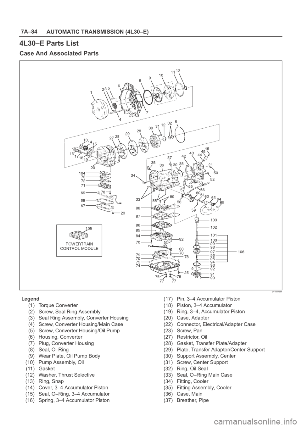
4L30–E Parts List
Case And Associated Parts
241RW014
Legend
(1) Torque Converter
(2) Screw, Seal Ring Assembly
(3) Seal Ring Assembly, Converter Housing
(4) Screw, Converter Housing/Main Case
(5) Screw, Converter Housing/Oil Pump
(6) Housing, Converter
(7) Plug, Converter Housing
(8) Seal, O–Ring
(9) Wear Plate, Oil Pump Body
(10) Pump Assembly, Oil
(11) Gasket
(12) Washer, Thrust Selective
(13) Ring, Snap
(14) Cover, 3–4 Accumulator Piston
(15) Seal, O–Ring, 3–4 Accumulator
(16) Spring, 3–4 Accumulator Piston(17) Pin, 3–4 Accumulator Piston
(18) Piston, 3–4 Accumulator
(19) Ring, 3–4, Accumulator Piston
(20) Case, Adapter
(22) Connector, Electrical/Adapter Case
(23) Screw, Pan
(27) Restrictor, Oil
(28) Gasket, Transfer Plate/Adapter
(29) Plate, Transfer Adapter/Center Support
(30) Support Assembly, Center
(31) Screw, Center Support
(32) Ring, Oil Seal
(33) Seal, O–Ring Main Case
(34) Fitting, Cooler
(35) Fitting Assembly, Cooler
(36) Case, Main
(37) Breather, Pipe
Page 2239 of 6000

7A–85 AUTOMATIC TRANSMISSION (4L30–E)
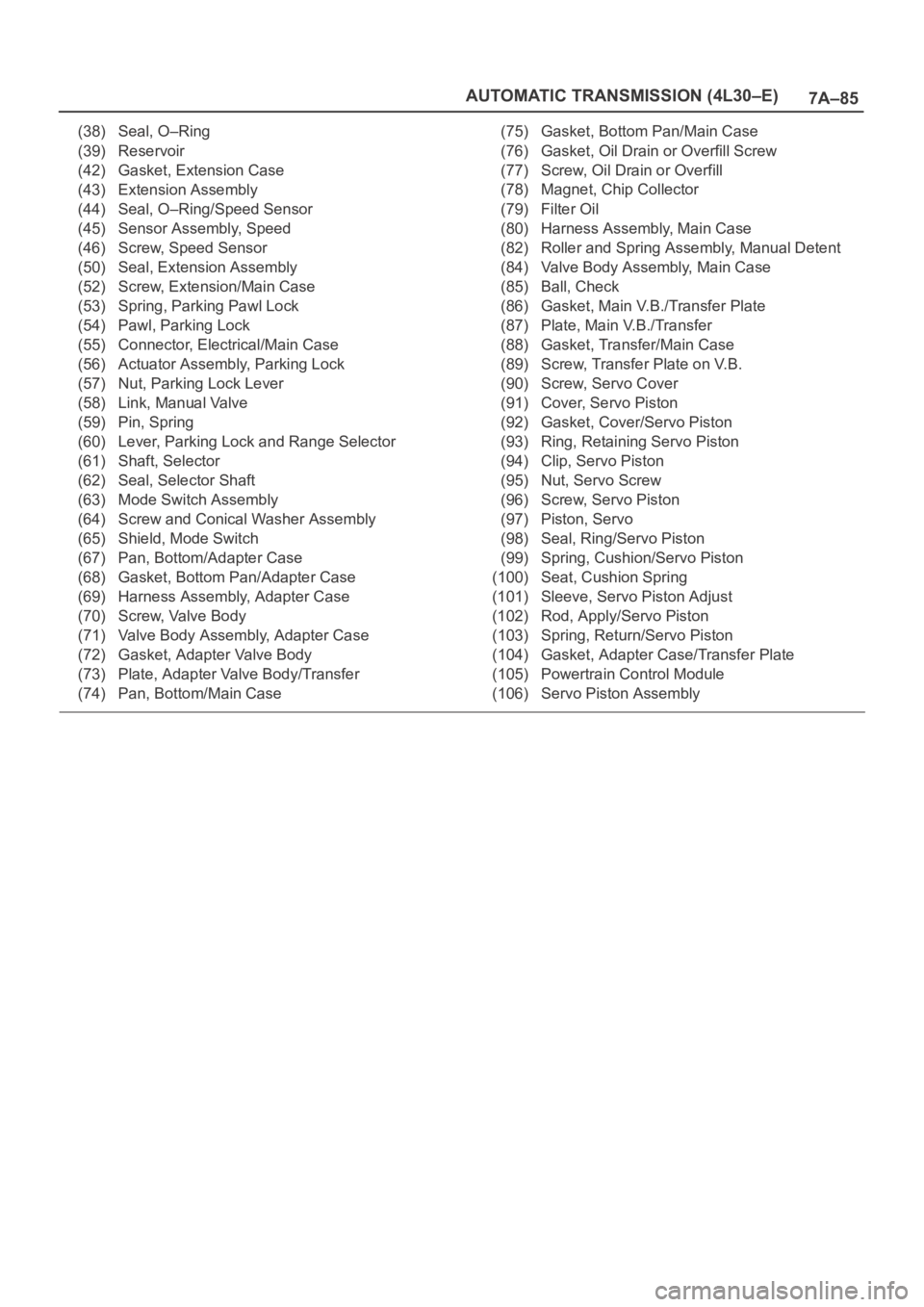
(38) Seal, O–Ring
(39) Reservoir
(42) Gasket, Extension Case
(43) Extension Assembly
(44) Seal, O–Ring/Speed Sensor
(45) Sensor Assembly, Speed
(46) Screw, Speed Sensor
(50) Seal, Extension Assembly
(52) Screw, Extension/Main Case
(53) Spring, Parking Pawl Lock
(54) Pawl, Parking Lock
(55) Connector, Electrical/Main Case
(56) Actuator Assembly, Parking Lock
(57) Nut, Parking Lock Lever
(58) Link, Manual Valve
(59) Pin, Spring
(60) Lever, Parking Lock and Range Selector
(61) Shaft, Selector
(62) Seal, Selector Shaft
(63) Mode Switch Assembly
(64) Screw and Conical Washer Assembly
(65) Shield, Mode Switch
(67) Pan, Bottom/Adapter Case
(68) Gasket, Bottom Pan/Adapter Case
(69) Harness Assembly, Adapter Case
(70) Screw, Valve Body
(71) Valve Body Assembly, Adapter Case
(72) Gasket, Adapter Valve Body
(73) Plate, Adapter Valve Body/Transfer
(74) Pan, Bottom/Main Case(75) Gasket, Bottom Pan/Main Case
(76) Gasket, Oil Drain or Overfill Screw
(77) Screw, Oil Drain or Overfill
(78) Magnet, Chip Collector
(79) Filter Oil
(80) Harness Assembly, Main Case
(82) Roller and Spring Assembly, Manual Detent
(84) Valve Body Assembly, Main Case
(85) Ball, Check
(86) Gasket, Main V.B./Transfer Plate
(87) Plate, Main V.B./Transfer
(88) Gasket, Transfer/Main Case
(89) Screw, Transfer Plate on V.B.
(90) Screw, Servo Cover
(91) Cover, Servo Piston
(92) Gasket, Cover/Servo Piston
(93) Ring, Retaining Servo Piston
(94) Clip, Servo Piston
(95) Nut, Servo Screw
(96) Screw, Servo Piston
(97) Piston, Servo
(98) Seal, Ring/Servo Piston
(99) Spring, Cushion/Servo Piston
(100) Seat, Cushion Spring
(101) Sleeve, Servo Piston Adjust
(102) Rod, Apply/Servo Piston
(103) Spring, Return/Servo Piston
(104) Gasket, Adapter Case/Transfer Plate
(105) Powertrain Control Module
(106) Servo Piston Assembly
Page 2322 of 6000

7B–4MANUAL TRANSMISSION
Diagnosis
ConditionPossible causeCorrection
Abnormal noiseFlywheel pilot bearing wornReplace
Bearings worn or broken (Mainshaft,
counter shaft, and transfer shaft)Replace
Gear tooth contact surfaces worn or
scuffed (Mainshaft, counter shaft,
reverse idler gear and transfer gears)Replace
Splines worn (Mainshaft,
synchronizer clutch hub)Replace
Gear or bearing thrust face seizedReplace
Lack of backlash between meshing
gearsReplace
Hard ShiftingImproper clutch pedal free playReadjust
Change lever sliding portions wornRepair or replace
Regrease
Shift block, shift rod and/or control
box sliding faces wornReplace
Shift arm and synchronizer sleeve
groove wornReplace worn parts
Thrust washer, collar, and/or gear
thrust faces worn (Mainshaft and
counter shaft thrust play)Replace worn parts
Synchronizer parts wornReplace
Walking or Jumping out of gearDetent ball wornReplace
Detent spring weakened or brokenReplace
Shift rod and/or control box sliding
faces wornReplace
Shift arm and synchronizer sleeve
groove wornReplace worn parts
Thrust washer, collar, and/or gear
thrust faces worn (Mainshaft and
counter shaft thrust play)Replace worn parts
Bearings worn or brokenReplace
Splines worn (Mainshaft,
synchronizer hub)Replace
Synchronizer spring weakened or
brokenReplace
Oil leakageLoose drain plug(s) and/or filler
plug(s)Tighten
Replenish oil
Defective or improperly installed
gasket(s)Replace
Oil seal worn or scratchedReplace
Page 2339 of 6000
MANUAL TRANSMISSION7B–21
Disassembly
1. Remove the drain plug and filler plug.
1. Remove the drain plug (1) and gasket.
2. Remove the filler plug (2) and gasket.
(6VE1)
220RW007
2. Remove the clutch release bearing and shift fork.
1. Remove the clutch release bearing (3) from the
front cover.
2. Remove the split pin (4). Remove the shaft from
the under. Remove the shift fork (5).
220RW086
3. Remove the switch.
1. Remove backup light switch (6) and gasket.
2. Remove neutral switch (7) and gasket (4JX1).
3. Remove 1st and 2nd switch (8) and gasket.
(4JX1)
220RW093
4. Remove the clutch housing.
1. Remove the 9 bolts.
241RW001
Page 2340 of 6000
7B–22MANUAL TRANSMISSION
2. Using a plastic hammer, carefully tap the clutch
housing.
(6VE1)
220RW008
5. Remove gear control box and gasket.
1. Remove the 6 bolts, gear control box and gasket.
(6VE1)
230RW001
6. Remove transfer adapter.
1. Using a hexagon wrench, remove the plug (1).
220RW010
2. Using a pin punch and hammer, drive out the
slotted spring pin (2).
230RW002
Page 2380 of 6000
7B–62MANUAL TRANSMISSION
10. Install the new snap ring.
226RW026
32. Install the shift arm bolts.
1. Install and torque the 2 shift arm bolts.
Torque: 20 Nꞏm (2.0 kgꞏm/14 lb ft)
226RW023
33. Install the shift arm slotted pin.
1. Using a pin punch and a hammer, drive in the
slotted pin to the shift arm.
226RW025
34. Install the transmission case.
1. Clean up the fitting surface.
2. Apply recommended liquid gasket (THREE
BOND 1281 or equivalent), as shown.
NOTE:
Don’t dry the liquid gasket.
220RW024
Page 2381 of 6000
MANUAL TRANSMISSION7B–63
3. Stand the transmission by the wood blocks.
4. Using a plastic hammer, tap the transmission
case and attach it to the intermediate plate.
NOTE: Be careful not to add over force to bearing.
220RW022
5. Using a snap ring expander, install the front
bearing shaft snap ring (1) and counter gear shaft
bearing snap ring (2).
226RW004
6. Turn over the transmission.
35. Install the front cover.
1. Clean up the fitting surface.
2. Apply recommended liquid gasket (THREE
BOND 1281 or equivalent), as shown.NOTE:
Don’t dry the liquid gasket.
220RW025
3. Clean up and dry the bolts.
4. Apply thread sealant (THREE BOND 1344 or
equivalent) to the 8 bolts.
5. Using 8 bolts, install the front cover to the
transmission case.
Torque: 17 Nꞏm (1.7 kgꞏm/12 lb ft)
NOTE:
Tighten the all bolts evenly.
Be careful not to damage the oil seal.
220RW018