1998 OPEL FRONTERA ESP
[x] Cancel search: ESPPage 5559 of 6000
6E–130
4JX1–TC ENGINE DRIVEABILITY AND EMISSIONS
Diagnostic Trouble Code (DTC) P1403 (Flash DTC 32)
EGR EVRV Fault
060RW135
Circuit Description
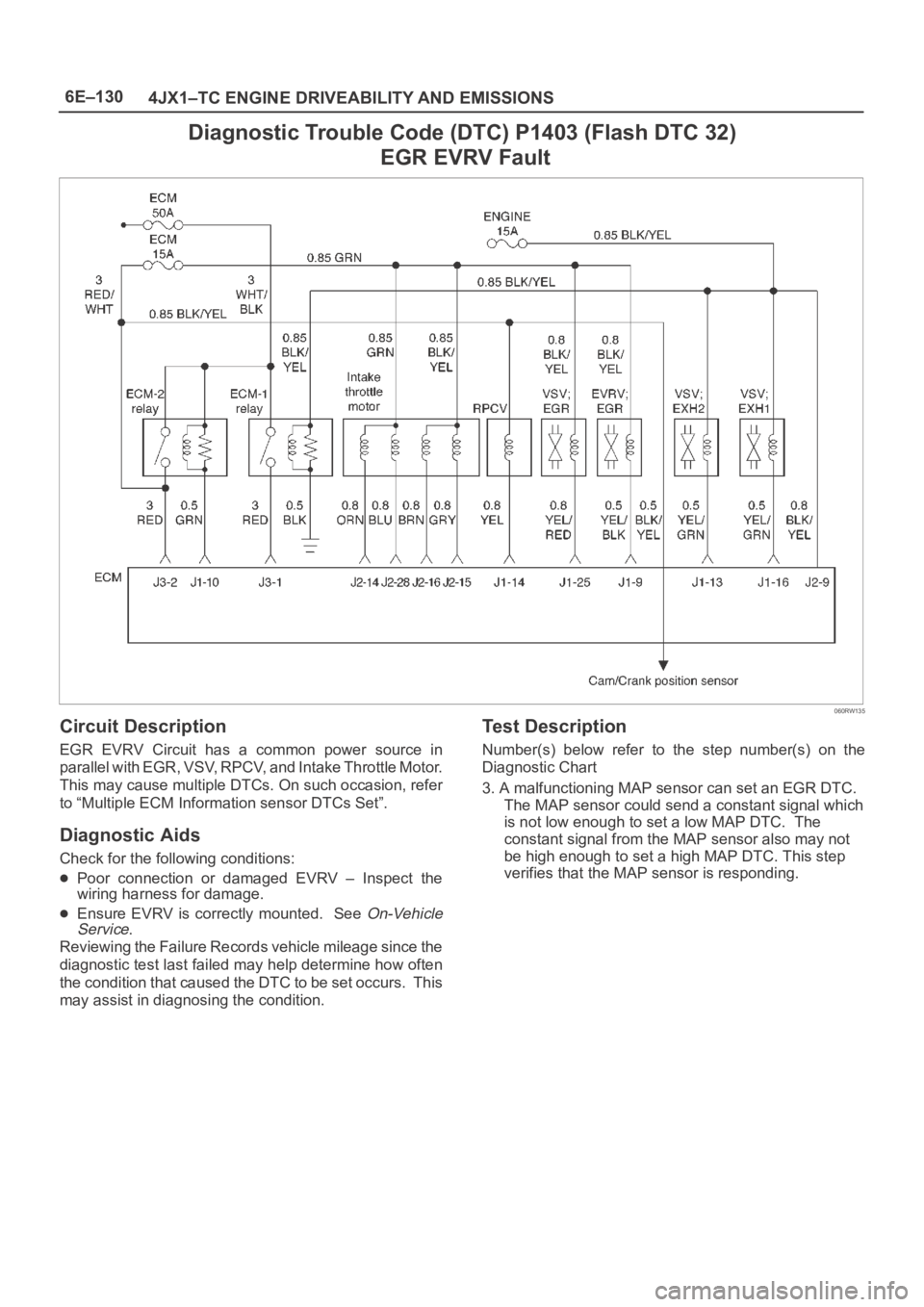
EGR EVRV Circuit has a common power source in
parallel with EGR, VSV, RPCV, and Intake Throttle Motor.
This may cause multiple DTCs. On such occasion, refer
to “Multiple ECM Information sensor DTCs Set”.
Diagnostic Aids
Check for the following conditions:
Poor connection or damaged EVRV – Inspect the
wiring harness for damage.
Ensure EVRV is correctly mounted. See On-Vehicle
Service.
Reviewing the Failure Records vehicle mileage since the
diagnostic test last failed may help determine how often
the condition that caused the DTC to be set occurs. This
may assist in diagnosing the condition.
Test Description
Number(s) below refer to the step number(s) on the
Diagnostic Chart
3. A malfunctioning MAP sensor can set an EGR DTC.
The MAP sensor could send a constant signal which
is not low enough to set a low MAP DTC. The
constant signal from the MAP sensor also may not
be high enough to set a high MAP DTC. This step
verifies that the MAP sensor is responding.
Page 5561 of 6000
6E–132
4JX1–TC ENGINE DRIVEABILITY AND EMISSIONS
Diagnostic Trouble Code (DTC) P1404 (Flash DTC 31)
EGR VSV Circuit
060RW135
Circuit Description
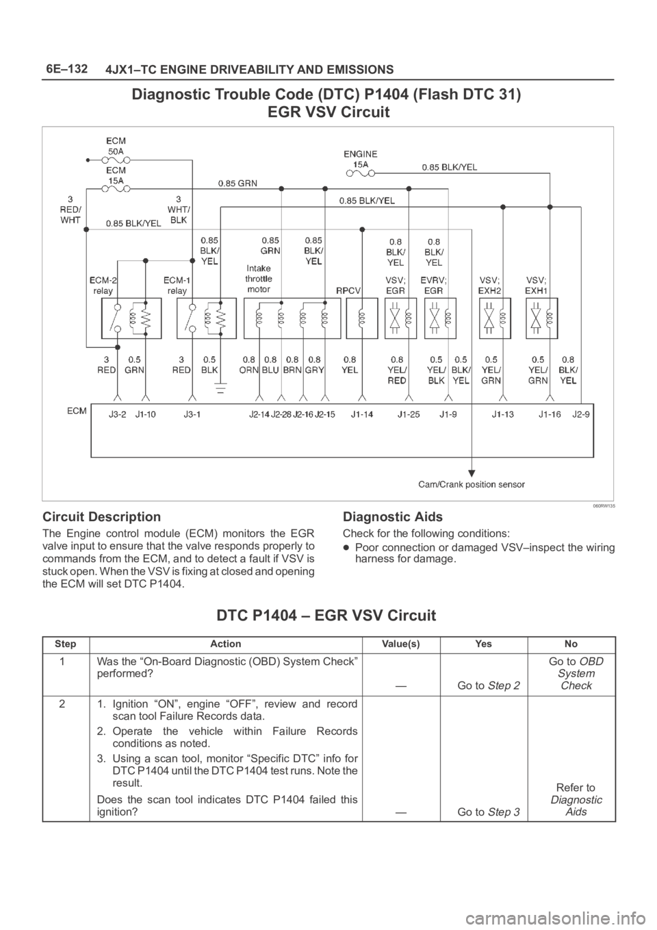
The Engine control module (ECM) monitors the EGR
valve input to ensure that the valve responds properly to
commands from the ECM, and to detect a fault if VSV is
stuck open. When the VSV is fixing at closed and opening
the ECM will set DTC P1404.
Diagnostic Aids
Check for the following conditions:
Poor connection or damaged VSV–inspect the wiring
harness for damage.
DTC P1404 – EGR VSV Circuit
StepActionVa l u e ( s )Ye sNo
1Was the “On-Board Diagnostic (OBD) System Check”
performed?
—Go to Step 2
Go to OBD
System
Check
21. Ignition “ON”, engine “OFF”, review and record
scan tool Failure Records data.
2. Operate the vehicle within Failure Records
conditions as noted.
3. Using a scan tool, monitor “Specific DTC” info for
DTC P1404 until the DTC P1404 test runs. Note the
result.
Does the scan tool indicates DTC P1404 failed this
ignition?
—Go to Step 3
Refer to
Diagnostic
Aids
Page 5655 of 6000
6E–226
4JX1–TC ENGINE DRIVEABILITY AND EMISSIONS
0018
Manifold Absolute Pressure (MAP) Sensor
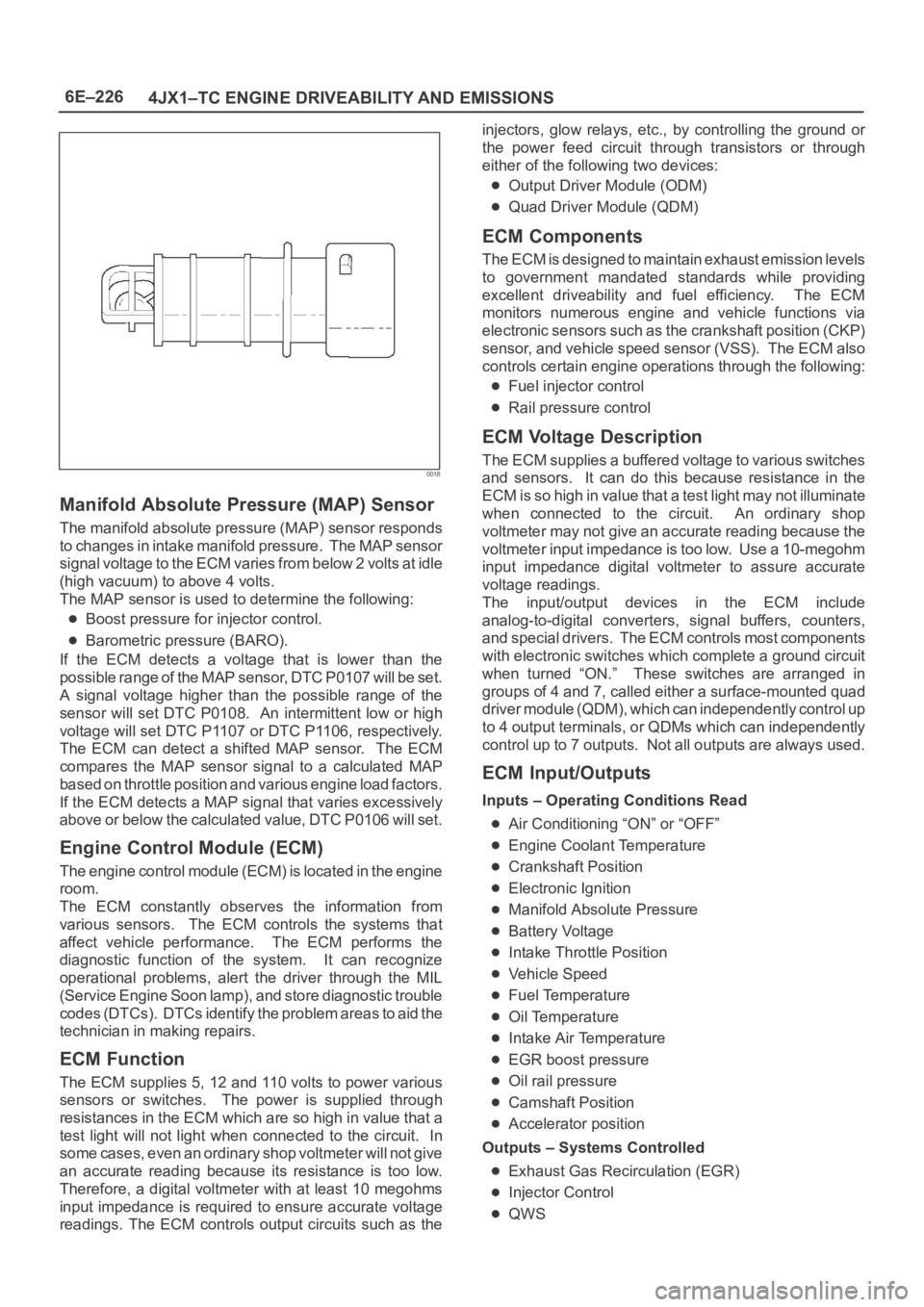
The manifold absolute pressure (MAP) sensor responds
to changes in intake manifold pressure. The MAP sensor
signal voltage to the ECM varies from below 2 volts at idle
(high vacuum) to above 4 volts.
The MAP sensor is used to determine the following:
Boost pressure for injector control.
Barometric pressure (BARO).
If the ECM detects a voltage that is lower than the
possible range of the MAP sensor, DTC P0107 will be set.
A signal voltage higher than the possible range of the
sensor will set DTC P0108. An intermittent low or high
voltage will set DTC P1107 or DTC P1106, respectively.
The ECM can detect a shifted MAP sensor. The ECM
compares the MAP sensor signal to a calculated MAP
based on throttle position and various engine load factors.
If the ECM detects a MAP signal that varies excessively
above or below the calculated value, DTC P0106 will set.
Engine Control Module (ECM)
The engine control module (ECM) is located in the engine
room.
The ECM constantly observes the information from
various sensors. The ECM controls the systems that
affect vehicle performance. The ECM performs the
diagnostic function of the system. It can recognize
operational problems, alert the driver through the MIL
(Service Engine Soon lamp), and store diagnostic trouble
codes (DTCs). DTCs identify the problem areas to aid the
technician in making repairs.
ECM Function
The ECM supplies 5, 12 and 110 volts to power various
sensors or switches. The power is supplied through
resistances in the ECM which are so high in value that a
test light will not light when connected to the circuit. In
some cases, even an ordinary shop voltmeter will not give
an accurate reading because its resistance is too low.
Therefore, a digital voltmeter with at least 10 megohms
input impedance is required to ensure accurate voltage
readings. The ECM controls output circuits such as theinjectors, glow relays, etc., by controlling the ground or
the power feed circuit through transistors or through
either of the following two devices:
Output Driver Module (ODM)
Quad Driver Module (QDM)
ECM Components
The ECM is designed to maintain exhaust emission levels
to government mandated standards while providing
excellent driveability and fuel efficiency. The ECM
monitors numerous engine and vehicle functions via
electronic sensors such as the crankshaft position (CKP)
sensor, and vehicle speed sensor (VSS). The ECM also
controls certain engine operations through the following:
Fuel injector control
Rail pressure control
ECM Voltage Description
The ECM supplies a buffered voltage to various switches
and sensors. It can do this because resistance in the
ECM is so high in value that a test light may not illuminate
when connected to the circuit. An ordinary shop
voltmeter may not give an accurate reading because the
voltmeter input impedance is too low. Use a 10-megohm
input impedance digital voltmeter to assure accurate
voltage readings.
The input/output devices in the ECM include
analog-to-digital converters, signal buffers, counters,
and special drivers. The ECM controls most components
with electronic switches which complete a ground circuit
when turned “ON.” These switches are arranged in
groups of 4 and 7, called either a surface-mounted quad
driver module (QDM), which can independently control up
to 4 output terminals, or QDMs which can independently
control up to 7 outputs. Not all outputs are always used.
ECM Input/Outputs
Inputs – Operating Conditions Read
Air Conditioning “ON” or “OFF”
Engine Coolant Temperature
Crankshaft Position
Electronic Ignition
Manifold Absolute Pressure
Battery Voltage
Intake Throttle Position
Vehicle Speed
Fuel Temperature
Oil Temperature
Intake Air Temperature
EGR boost pressure
Oil rail pressure
Camshaft Position
Accelerator position
Outputs – Systems Controlled
Exhaust Gas Recirculation (EGR)
Injector Control
QWS
Page 5662 of 6000
ENGINE EXHAUST 6F – 3
ON-VEHICLE SERVICE
FRONT EXHAUST PIPE
Rattles and noise vibrations in the exhaust system are
usually caused by misalignment of parts. When aligning
the system, leave all bolts or nuts loose until all parts
are properly aligned; then tighten, working from front to
rear.
1. Check connections for looseness or damage,
especially for exhaust gas leakage.
2. Check clamps and rubbers for weakness, cracks or
damage.3. If any part of the converter heat shield is damaged
or dented to the extent that it contacts the catalyst,
repair or replace.
4. Check for dents or damage and for any holes or
cracks caused by corrosion.
3
2 1
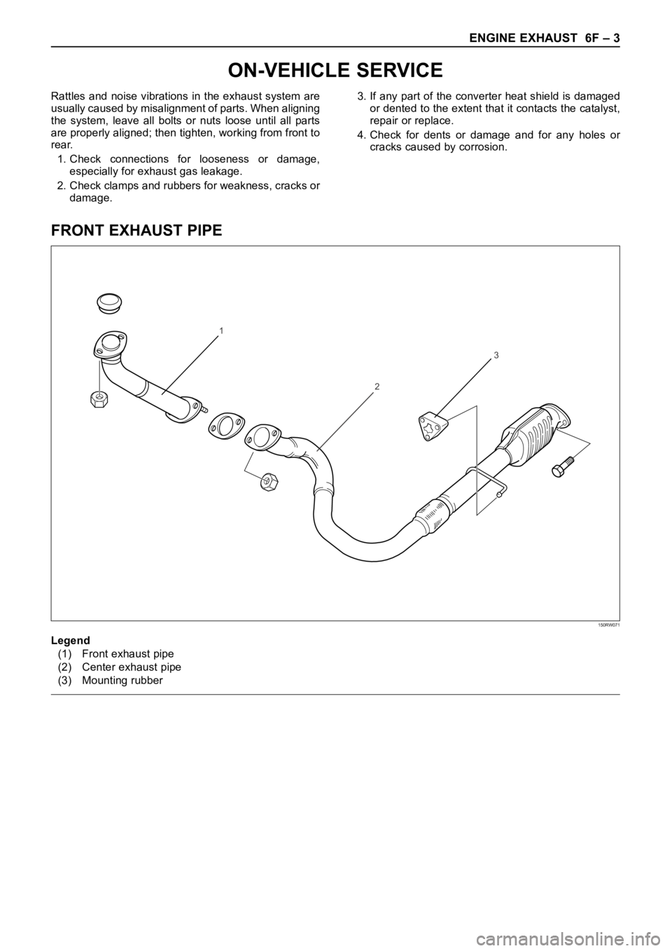
Legend
(1) Front exhaust pipe
(2) Center exhaust pipe
(3) Mounting rubber
150RW071
Page 5718 of 6000
7A–29 AUTOMATIC TRANSMISSION (4L30–E)
Changing Transmission Fluid
There is no need to change the transmission fluid unless
the transmission is used under one or more of the
following heavy duty conditions.
A. Repeated short trips
B. Driving on rough roads
C. Driving on dusty roads
D. Towing a trailer
If the vehicle is used under these conditions, change the
fluid every 20,000 miles (32,000 km).
More over, the remaining life percentage of ATF can be
estimated by using Tech 2 as an auxiliary tool to judge the
right time for ATF replacement.
The remaining life percentage is calculated from ATF’S
heat history. When it is close to 0%, ATF replacement is
recommended.
1. Place a large drain pan under the oil pan.
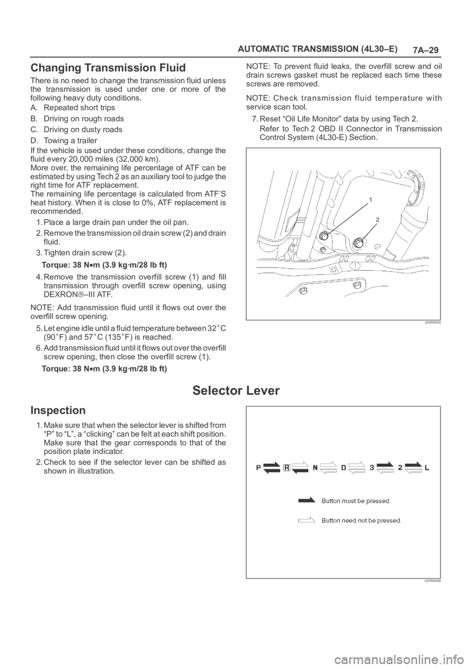
2. Remove the transmission oil drain screw (2) and drain
fluid.
3. Tighten drain screw (2).
Torque: 38 N
m (3.9 kgꞏm/28 lb ft)
4. Remove the transmission overfill screw (1) and fill
transmission through overfill screw opening, using
DEXRON
–III ATF.
NOTE: Add transmission fluid until it flows out over the
overfill screw opening.
5. Let engine idle until a fluid temperature between 32
C
(90
F) and 57C (135F) is reached.
6. Add transmission fluid until it flows out over the overfill
screw opening, then close the overfill screw (1).
Torque: 38 N
m (3.9 kgꞏm/28 lb ft)NOTE: To prevent fluid leaks, the overfill screw and oil
drain screws gasket must be replaced each time these
screws are removed.
NOTE: Check transmission fluid temperature with
service scan tool.
7. Reset “Oil Life Monitor” data by using Tech 2.
Refer to Tech 2 OBD II Connector in Transmission
Control System (4L30-E) Section.
242RW003
Selector Lever
Inspection
1. Make sure that when the selector lever is shifted from
“P” to “L”, a “clicking” can be felt at each shift position.
Make sure that the gear corresponds to that of the
position plate indicator.
2. Check to see if the selector lever can be shifted as
shown in illustration.
C07RW009
Page 5728 of 6000
7A–39 AUTOMATIC TRANSMISSION (4L30–E)
Solenoid (Main Case Valve Body)
Removal
1. Raise the vehicle and support it on jack stands.
2. Disconnect battery ground cable.
3. Remove transfer and exhaust protectors.
4. Drain fluid.
5. Remove exhaust pipe and disconnect oxygen sensor
connector.
6. Support transfer case with a jack and remove third
crossmember.
7. Remove sixteen 10 mm screws, main case oil pan,
magnet, and gasket.
8. Remove three 13 mm screws, oil filter.
9. Disconnect wiring harness from band control
solenoid and shift solenoids. Pull only on connectors,
not on wiring harness.
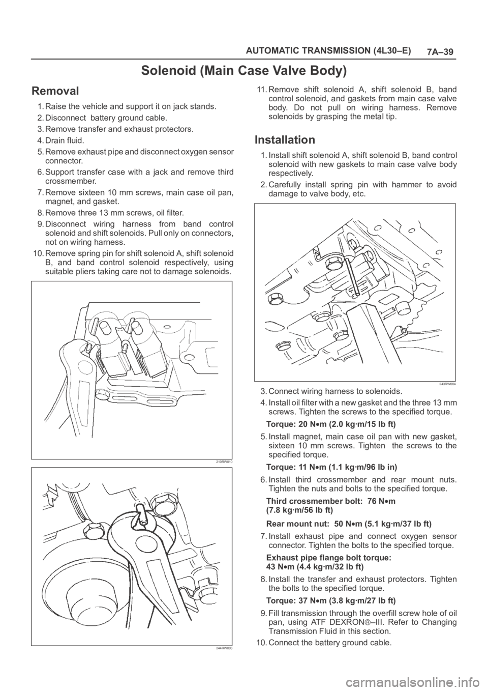
10. Remove spring pin for shift solenoid A, shift solenoid
B, and band control solenoid respectively, using
suitable pliers taking care not to damage solenoids.
210RW010
244RW003
11. Remove shift solenoid A, shift solenoid B, band
control solenoid, and gaskets from main case valve
body. Do not pull on wiring harness. Remove
solenoids by grasping the metal tip.
Installation
1. Install shift solenoid A, shift solenoid B, band control
solenoid with new gaskets to main case valve body
respectively.
2. Carefully install spring pin with hammer to avoid
damage to valve body, etc.
243RW004
3. Connect wiring harness to solenoids.
4. Install oil filter with a new gasket and the three 13 mm
screws. Tighten the screws to the specified torque.
To r q u e : 2 0 N
m (2.0 kgꞏm/15 lb ft)
5. Install magnet, main case oil pan with new gasket,
sixteen 10 mm screws. Tighten the screws to the
specified torque.
To r q u e : 11 N
m (1.1 kgꞏm/96 lb in)
6. Install third crossmember and rear mount nuts.
Tighten the nuts and bolts to the specified torque.
Third crossmember bolt: 76 N
m
(7.8 kgꞏm/56 lb ft)
Rear mount nut: 50 N
m (5.1 kgꞏm/37 lb ft)
7. Install exhaust pipe and connect oxygen sensor
connector. Tighten the bolts to the specified torque.
Exhaust pipe flange bolt torque:
43 N
m(4.4kgꞏm/32lbft)
8. Install the transfer and exhaust protectors. Tighten
the bolts to the specified torque.
Torque: 37 N
m (3.8 kgꞏm/27 lb ft)
9. Fill transmission through the overfill screw hole of oil
pan, using ATF DEXRON
–III. Refer to Changing
Transmission Fluid in this section.
10. Connect the battery ground cable.
Page 5788 of 6000

AUTOMATIC TRANSMISSION (AW30-40LE) 7A–7
CONTROL AND FUNCTIONS
Item Description
Shift and lock-up control • In D range, speed change point and Lock-up point can be changed by
setting pattern selection switch to "POWER", "NORMAL" or "WINTER"
mode.
• Gear shift position in the conditions made up of transmission shift positions
(D.2.L) combined with pattern selection switch (POWER, NORMAL, and
WINTER) can be controlled in accordance with vehicle speed and the
opening of throttle valve.
Overdrive cut control • If O/D OFF switch is set on in D range (O/D OFF lamp ON), gear shift to O/
D is not effected.
• Overdrive is released at O/D OFF switch on and high transmission oil
temperature (More than 130
C).
However, to prevent engine over revolution
•4
3 shifting at vehicle speed is less than 118 km/h.
•3
4 shifting at vehicle speed is more than 131 km/h.
Lock-up cut control • In D range, 3rd or O/D lock-up is conducted in "POWER" or "NORMAL"
mode.
• In 2, L range, lock-up is off in the whole area.
• Lock-up timing is controlled to reduce gear shift shock using kind of gear
shift (shift up, etc.) lock-up status at the time of gear shift judgement, gear
step and throttle opening after gear shift.
• Lock-up is released at brake on or high transmission oil temperature (More
than 130
C).
• Lock-up is prohibited when idling is defected by throttle position sensor.
Driving mode select control • The TCM selects a suitable driving mode from the nine kinds for the variety
driving condition.
i) Economy mode ii) Power mode iii) Winter mode iv) HOT1 mode v) HOT2
mode vi) L4 mode vii) Slope mode (Up slope 1, Up slope 2 and Down
slope mode)
• The priority of driving mode:
Economy < Power < Slope < L4 < Winter < HOT1 < HOT2
Squat control • When the TCM detects D signal on, the TCM controls 1–3–1 shift by
setting a timer, in order to improve the shift feel at N
D.
Line pressure control • The TCM output current which corresponds to throttle oil pressure to
pressure control solenoid based on throttle opening.
Indicate oil temperature warning
function• If the transmission oil temperature sensor senses that transmission oil
temperature is greater than 146
C, the TCM turn on A/T OIL TEMP
warning lamp. (The warning lamp is turned off, if oil temperature is less
than 126
C.)
L4 mode control • The TCM judges whether the transfer is engaged in high or low based on
the ratio rpm data from output speed sensor in the transmission and the
rpm data from speed meter sensor to select the shift map.
Up and down hill control • The TCM judges up and down hill, and change shift pattern based on
throttle opening and acceleration.
Correct oil temperature control • If the temperature exceeds a predetermined value, the TCM selects the
high oil temperature shift point for downshifting, thus preventing the oil
temperature from rising. (More than 130
C, D range)
Page 5792 of 6000
AUTOMATIC TRANSMISSION (AW30-40LE) 7A–11
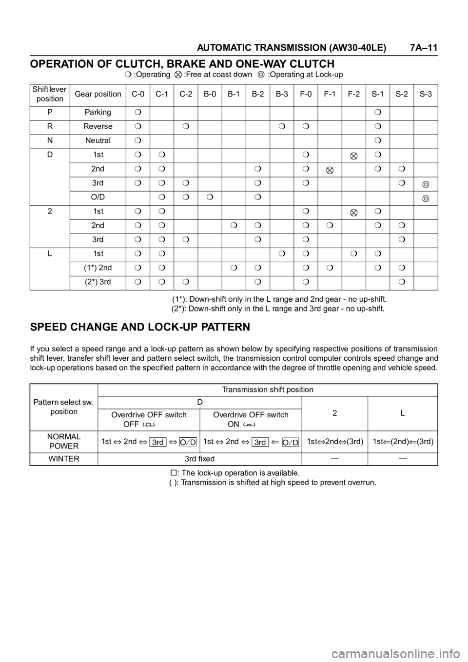
OPERATION OF CLUTCH, BRAKE AND ONE-WAY CLUTCH
:Operating :Free at coast down :Operating at Lock-up
(1*): Down-shift only in the L range and 2nd
gear - no up-shift.
(2*): Down-shift only in the L range and 3rd gear - no up-shift.
SPEED CHANGE AND LOCK-UP PATTERN
If you select a speed range and a lock-up pattern as shown below by specifying respective positions of transmission
shift lever, transfer shift lever and pattern select switch, the transmission control computer controls speed change and
lock-up operations based on the specified pattern in accordance with the degree of throttle opening and vehicle speed.
: The lock-up operation is available.
( ): Transmission is shifted at high speed to prevent overrun.
Shift lever
positionGear positionC-0C-1C-2B-0B-1B-2B-3F-0F-1F-2S-1S-2S-3
PParking
RReverse
NNeutral
D1st
2nd
3rd
O/D
21st
2nd
3rd
L1st
(1*) 2nd
(2*) 3rd
Pattern select sw.
positionTransmission shift position
D
2L
Overdrive OFF switch
OFF Overdrive OFF switch
ON
NORMAL
POWER1st
2nd 1st 2nd 1st2nd(3rd) 1st(2nd)(3rd)
WINTER 3rd fixed──