1998 OPEL FRONTERA ESP
[x] Cancel search: ESPPage 5823 of 6000
7A–42 AUTOMATIC TRANSMISSION (AW30-40LE)
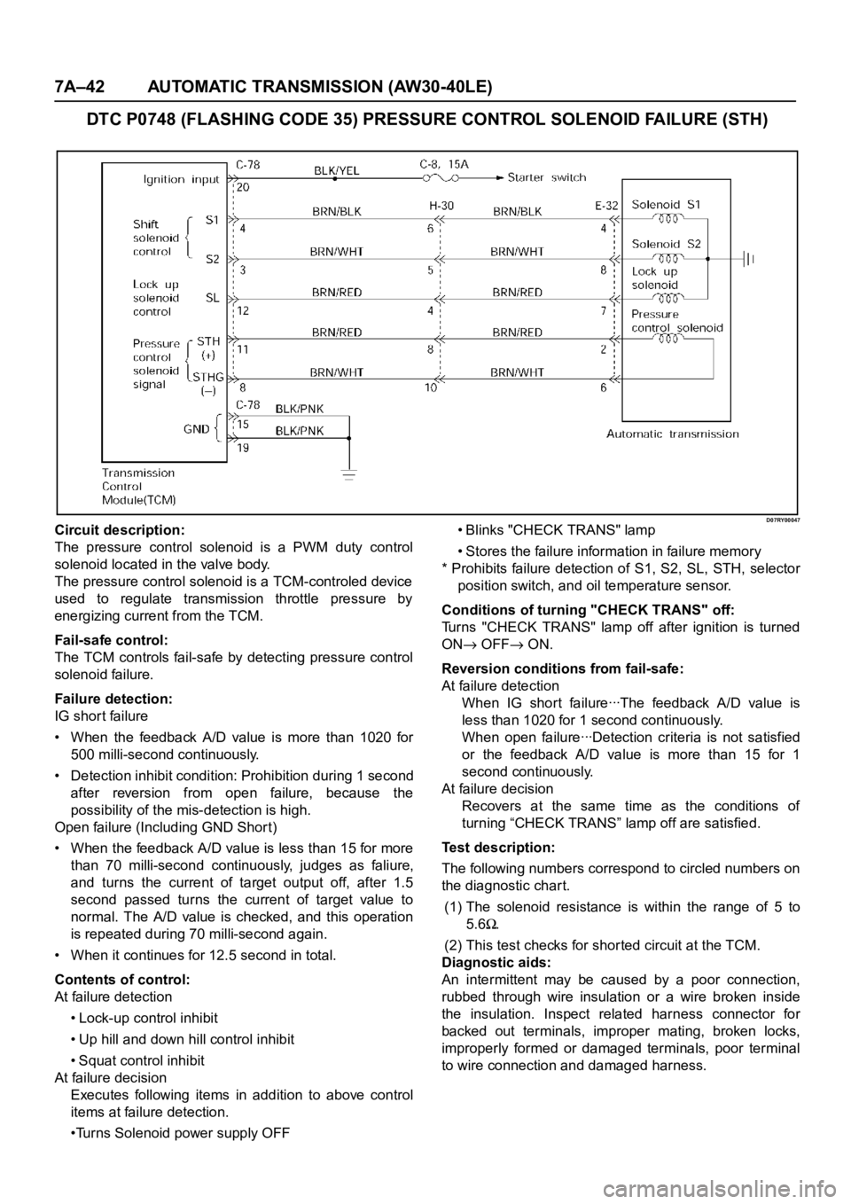
DTC P0748 (FLASHING CODE 35) PRESSURE CONTROL SOLENOID FAILURE (STH)
D07RY00047Circuit description:
The pressure control solenoid is a PWM duty control
solenoid located in the valve body.
The pressure control solenoid is a TCM-controled device
used to regulate transmission throttle pressure by
energizing current from the TCM.
Fail-safe control:
The TCM controls fail-safe by detecting pressure control
solenoid failure.
Failure detection:
IG shor t failure
• When the feedback A/D value is more than 1020 for
500 milli-second continuously.
• Detection inhibit condition: Prohibition during 1 second
after reversion from open failure, because the
possibility of the mis-detection is high.
Open failure (Including GND Shor t)
• When the feedback A/D value is less than 15 for more
than 70 milli-second continuously, judges as faliure,
and turns the current of target output off, after 1.5
second passed turns the current of target value to
normal. The A/D value is checked, and this operation
is repeated during 70 milli-second again.
• When it continues for 12.5 second in total.
Contents of control:
At failure detection
• Lock-up control inhibit
• Up hill and down hill control inhibit
• Squat control inhibit
At failure decision
Executes following items in addition to above control
items at failure detection.
•Turns Solenoid power supply OFF• Blinks "CHECK TRANS" lamp
• Stores the failure information in failure memory
* Prohibits failure detection of S1, S2, SL, STH, selector
position switch, and oil temperature sensor.
Conditions of turning "CHECK TRANS" off:
Turns "CHECK TRANS" lamp off after ignition is turned
ON
OFF ON.
Reversion conditions from fail-safe:
At failure detection
W h e n I G sh o r t fa i l u re ꞏꞏꞏT h e fe e d ba ck A / D va l u e i s
less than 1020 for 1 second continuously.
W h e n o p e n fa i l u re ꞏꞏꞏD e t e c t i o n c r i t e r i a i s n o t s a t i s f i e d
or the feedback A/D value is more than 15 for 1
second continuously.
At failure decision
Recovers at the same time as the conditions of
turning “CHECK TRANS” lamp off are satisfied.
Test description:
The following numbers correspond to circled numbers on
the diagnostic char t.
(1) The solenoid resistance is within the range of 5 to
5.6
.
(2) This test checks for shor ted circuit at the TCM.
Diagnostic aids:
An intermittent may be caused by a poor connection,
rubbed through wire insulation or a wire broken inside
the insulation. Inspect related harness connector for
backed out terminals, improper mating, broken locks,
improperly formed or damaged terminals, poor terminal
to wire connection and damaged harness.
Page 5826 of 6000

AUTOMATIC TRANSMISSION (AW30-40LE) 7A–45
• Changes solenoid output pattern as following figure
The shift theory at shift solenoid failure
At failure decision
Executes following items in addition to above control
items at failure detection.
•Turns Solenoid power supply OFF
•Blinks "CHECK TRANS" lamp
•Stores the failure information in failure-memory
*Prohibits failure detection of S1, S2, SL, STH,
Selector position switch, and Oil temp. sensor.
Conditions of turning "CHECK TRANS" off:
Turns "CHECK TRANS" lamp off after ignition is turned
ON
OFF ON.
Reversion conditions from fail-safe:
At failure detection
When a normal judgment is obtained by rechecking
during shifting.
At failure decision
Recovers at the same time as the conditions of
turning “CHECK TRANS” lamp off are satisfied.
Test description:
The following numbers correspond to circled numbers on
the diagnostic char t.
(1) With the key "ON", the voltage between the TCM
terminals (C78-4) and (C78-15 or 19) is 8 to 16V.
(2) When the driving wheels revolve with the 3rd speed
gear, the voltage is 1 V or less.
(3) The solenoid resistance is within the range of 11 to
15
.
Diagnostic aids:
In case of faulty connection, open or shor ted circuit to
the TCM terminal (C78-4), DTC P0753 is displayed. A
intermittent failure may be caused by a poor connection,
rubbed through wire insulation or a wire broke inside the
insulation.Shift
lever
Po s i t i o nNormal S1 failure S2 filure S1 and S2 failure
Gear S1 S2 Gear S1 S2 Gear S1 S2 Gear S1 S2
D1
3
1
O/D 2O/D3
O/DO/D
213
1
3 2O/D3
L1313
2O/D
Page 5829 of 6000
7A–48 AUTOMATIC TRANSMISSION (AW30-40LE)
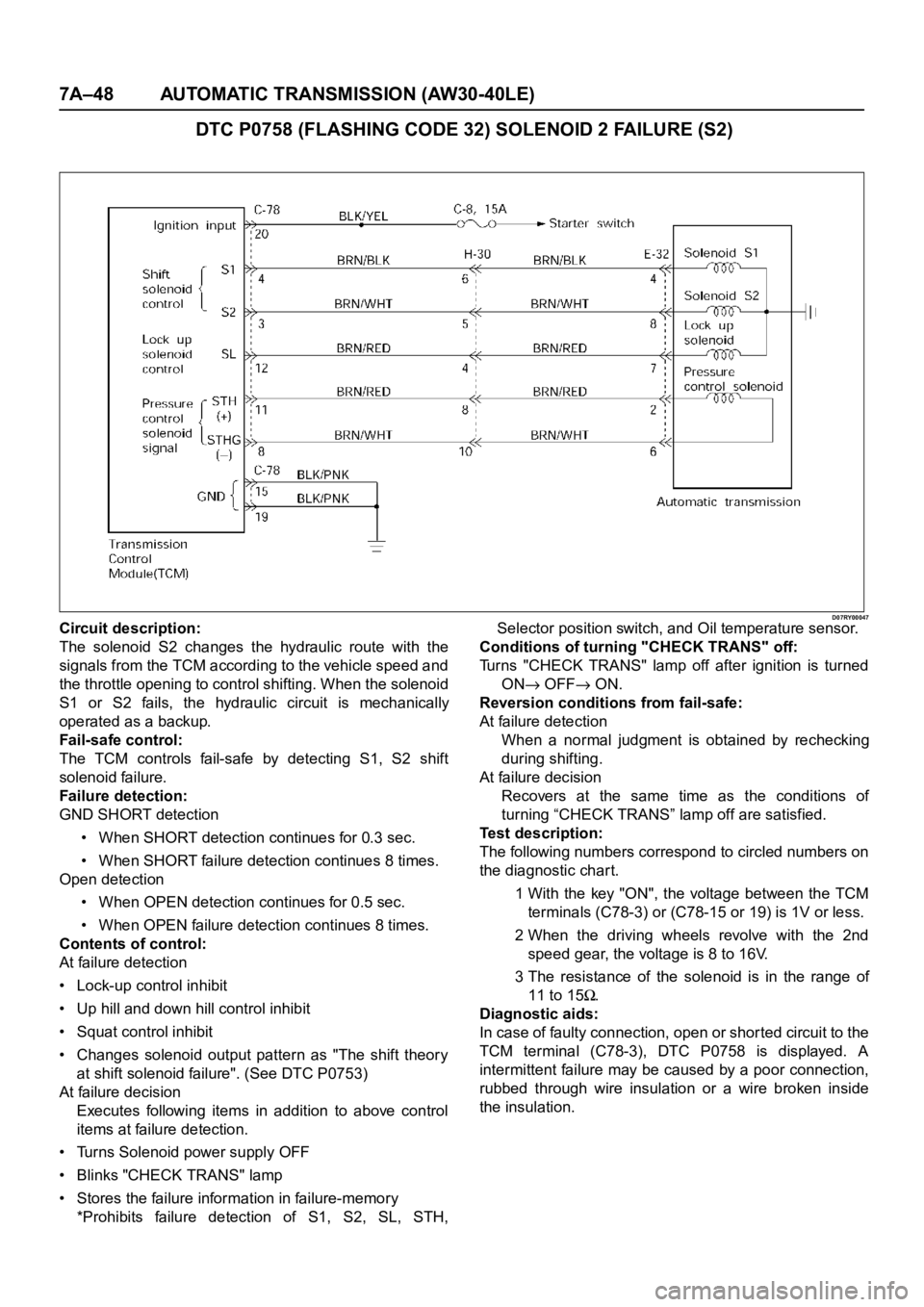
DTC P0758 (FLASHING CODE 32) SOLENOID 2 FAILURE (S2)
D07RY00047Circuit description:
The solenoid S2 changes the hydraulic route with the
signals from the TCM according to the vehicle speed and
the throttle opening to control shifting. When the solenoid
S1 or S2 fails, the hydraulic circuit is mechanically
operated as a backup.
Fail-safe control:
The TCM controls fail-safe by detecting S1, S2 shift
solenoid failure.
Failure detection:
GND SHORT detection
• When SHORT detection continues for 0.3 sec.
• When SHORT failure detection continues 8 times.
Open detection
• When OPEN detection continues for 0.5 sec.
• When OPEN failure detection continues 8 times.
Contents of control:
At failure detection
• Lock-up control inhibit
• Up hill and down hill control inhibit
• Squat control inhibit
• Changes solenoid output pattern as "The shift theory
at shift solenoid failure". (See DTC P0753)
At failure decision
Executes following items in addition to above control
items at failure detection.
• Turns Solenoid power supply OFF
• Blinks "CHECK TRANS" lamp
• Stores the failure information in failure-memory
*Prohibits failure detection of S1, S2, SL, STH,Selector position switch, and Oil temperature sensor.
Conditions of turning "CHECK TRANS" off:
Turns "CHECK TRANS" lamp off after ignition is turned
ON
OFF ON.
Reversion conditions from fail-safe:
At failure detection
When a normal judgment is obtained by rechecking
during shifting.
At failure decision
Recovers at the same time as the conditions of
turning “CHECK TRANS” lamp off are satisfied.
Test description:
The following numbers correspond to circled numbers on
the diagnostic char t.
1 With the key "ON", the voltage between the TCM
terminals (C78-3) or (C78-15 or 19) is 1V or less.
2 When the driving wheels revolve with the 2nd
speed gear, the voltage is 8 to 16V.
3 The resistance of the solenoid is in the range of
11 to 15
.
Diagnostic aids:
In case of faulty connection, open or shor ted circuit to the
TCM terminal (C78-3), DTC P0758 is displayed. A
intermittent failure may be caused by a poor connection,
rubbed through wire insulation or a wire broken inside
the insulation.
Page 5831 of 6000
7A–50 AUTOMATIC TRANSMISSION (AW30-40LE)
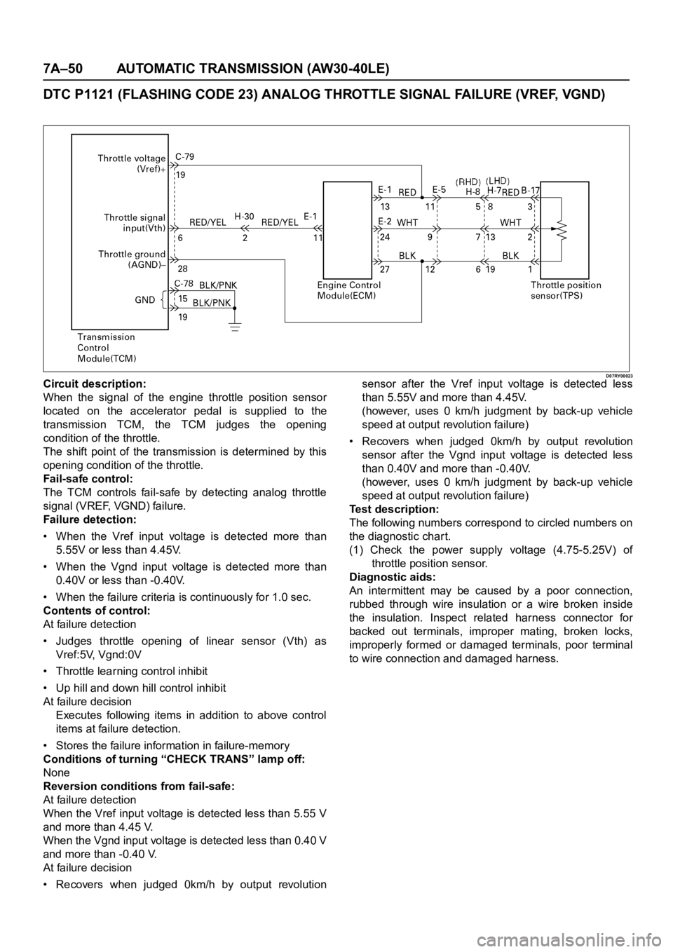
DTC P1121 (FLASHING CODE 23) ANALOG THROTTLE SIGNAL FAILURE (VREF, VGND)
D07RY00023Circuit description:
When the signal of the engine throttle position sensor
located on the accelerator pedal is supplied to the
transmission TCM, the TCM judges the opening
condition of the throttle.
The shift point of the transmission is determined by this
opening condition of the throttle.
Fail-safe control:
The TCM controls fail-safe by detecting analog throttle
signal (VREF, VGND) failure.
Failure detection:
• When the Vref input voltage is detected more than
5.55V or less than 4.45V.
• When the Vgnd input voltage is detected more than
0.40V or less than -0.40V.
• When the failure criteria is continuously for 1.0 sec.
Contents of control:
At failure detection
• Judges throttle opening of linear sensor (Vth) as
Vref:5V, Vgnd:0V
• Throttle learning control inhibit
• Up hill and down hill control inhibit
At failure decision
Executes following items in addition to above control
items at failure detection.
• Stores the failure information in failure-memory
Conditions of turning “CHECK TRANS” lamp off:
None
Reversion conditions from fail-safe:
At failure detection
When the Vref input voltage is detected less than 5.55 V
and more than 4.45 V.
When the Vgnd input voltage is detected less than 0.40 V
and more than -0.40 V.
At failure decision
• Recovers when judged 0km/h by output revolutionsensor after the Vref input voltage is detected less
than 5.55V and more than 4.45V.
(however, uses 0 km/h judgment by back-up vehicle
speed at output revolution failure)
• Recovers when judged 0km/h by output revolution
sensor after the Vgnd input voltage is detected less
than 0.40V and more than -0.40V.
(however, uses 0 km/h judgment by back-up vehicle
speed at output revolution failure)
Test description:
The following numbers correspond to circled numbers on
the diagnostic char t.
(1) Check the power supply voltage (4.75-5.25V) of
throttle position sensor.
Diagnostic aids:
An intermittent may be caused by a poor connection,
rubbed through wire insulation or a wire broken inside
the insulation. Inspect related harness connector for
backed out terminals, improper mating, broken locks,
improperly formed or damaged terminals, poor terminal
to wire connection and damaged harness.
Page 5843 of 6000
7A–62 AUTOMATIC TRANSMISSION (AW30-40LE)
826RY00018
F07RY00024
MANUAL SHIFTING TEST
NOTE:
With this test, it can be determined whether the trouble lies
within the electrical circuit or is a mechanical problem in
the transmission.
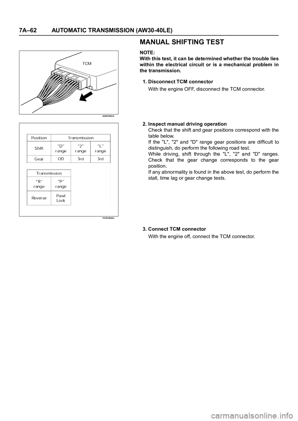
1. Disconnect TCM connector
With the engine OFF, disconnect the TCM connector.
2. Inspect manual driving operation
Check that the shift and gear positions correspond with the
table below.
If the "L", "2" and "D" range gear positions are difficult to
distinguish, do perform the following road test.
While driving, shift through the "L", "2" and "D" ranges.
Check that the gear change corresponds to the gear
position.
If any abnormality is found in the above test, do perform the
stall, time lag or gear change tests.
3. Connect TCM connector
With the engine off, connect the TCM connector.
Page 5861 of 6000
7A–80 AUTOMATIC TRANSMISSION (AW30-40LE)
256RY00001
256RW012
256RW013
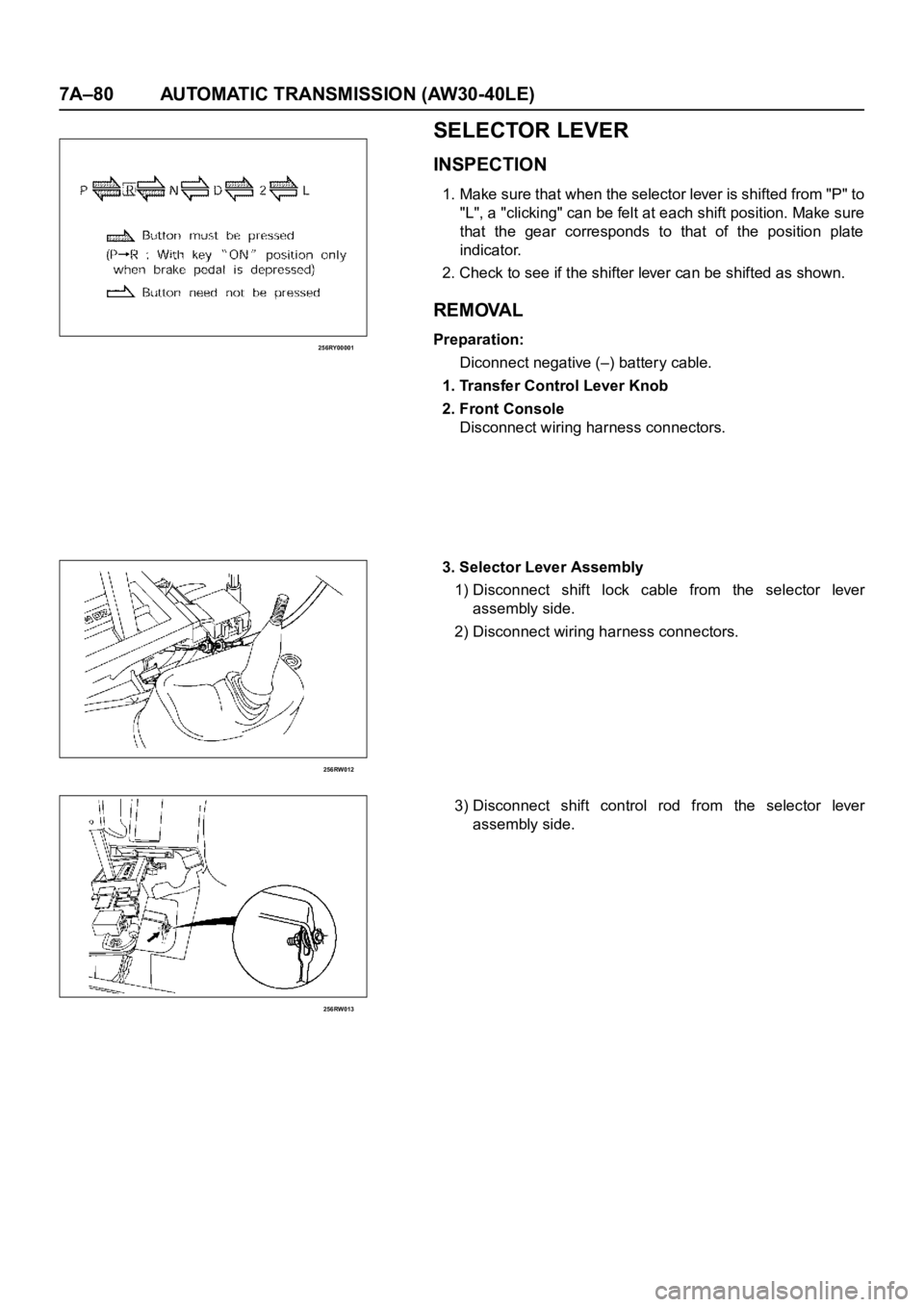
SELECTOR LEVER
INSPECTION
1. Make sure that when the selector lever is shifted from "P" to
"L", a "clicking" can be felt at each shift position. Make sure
that the gear corresponds to that of the position plate
indicator.
2. Check to see if the shifter lever can be shifted as shown.
REMOVAL
Preparation:
Diconnect negative (–) battery cable.
1. Transfer Control Lever Knob
2. Front Console
Disconnect wiring harness connectors.
3. Selector Lever Assembly
1) Disconnect shift lock cable from the selector lever
assembly side.
2) Disconnect wiring harness connectors.
3) Disconnect shift control rod from the selector lever
assembly side.
Page 5888 of 6000

AUTOMATIC TRANSMISSION (AW30-40LE) 7A–107
DISASSEMBLY, INSPECTION AND
REASSEMBLY OF MINOR COMPONENTS
The instructions here are organized so that you work on only
one component group at a time.
This will help avoid confusion from similar-looking parts of
different subassemblies being on your workbench at the same
time.
The component groups are inspected and repaired from the
converter housing side.
As much as possible, complete the inspection, repair and
reassembly before proceeding to the next component group. If
a component group cannot be reassembled because parts are
being ordered, be sure to keep all parts of that group in a
separate container while proceeding with disassembly,
inspection, repair and reassembly of other component groups.
Recommended ATF type BESCO ATF II or III.
GENERAL CLEANING NOTES:
1. All disassembled parts should be washed clean and any
fluid passages and holes blown through with compressed
air.
2. When using compressed air to dry parts, always aim away
from yourself to prevent accidentally spraying automatic
transmission fluid in your face.
3. The recommended automatic transmission fluid should be
used for cleaning.
PARTS ARRANGEMENT:
1. After cleaning, the par ts should be arranged in proper order
to allow performing inspection, repairs, and reassembly
with efficiency.
2. When disassembling a valve body, be sure to keep each
valve together with the corresponding spring.
3. New brakes and clutches that are to be used for
replacement must be soaked in transmission fluid for at
least thir ty before assembly.
GENERAL ASSEMBLY:
1. All oil seal rings, clutch discs, clutch plates, rotating parts,
and sliding surfaces should be coated with transmission
fluid prior to reassembly.
2. All gaskets and rubber O-rings should be replaced.
3. Make sure that ends of a snap ring are not aligned with one
of the cutouts and are installed in the groove correctly.
4. If a worn bushing is to be replaced, the subassembly
containing that bushing must be replaced.
5.Check thrust bearings and races for wear or damage.
Replace if necessary.
6. Use petroleum jelly or vaseline to keep par ts in place.