1998 OPEL FRONTERA ESP
[x] Cancel search: ESPPage 4888 of 6000
6E–231 ENGINE DRIVEABILITY AND EMISSIONS
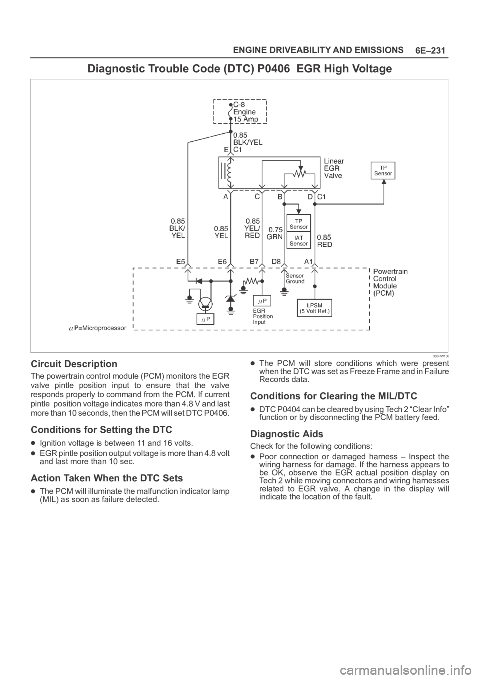
Diagnostic Trouble Code (DTC) P0406 EGR High Voltage
D06RW106
Circuit Description
The powertrain control module (PCM) monitors the EGR
valve pintle position input to ensure that the valve
responds properly to command from the PCM. If current
pintle position voltage indicates more than 4.8 V and last
more than 10 seconds, then the PCM will set DTC P0406.
Conditions for Setting the DTC
Ignition voltage is between 11 and 16 volts.
EGR pintle position output voltage is more than 4.8 volt
and last more than 10 sec.
Action Taken When the DTC Sets
The PCM will illuminate the malfunction indicator lamp
(MIL) as soon as failure detected.
The PCM will store conditions which were present
when the DTC was set as Freeze Frame and in Failure
Records data.
Conditions for Clearing the MIL/DTC
DTC P0404 can be cleared by using Tech 2 “Clear Info”
function or by disconnecting the PCM battery feed.
Diagnostic Aids
Check for the following conditions:
Poor connection or damaged harness – Inspect the
wiring harness for damage. If the harness appears to
be OK, observe the EGR actual position display on
Tech 2 while moving connectors and wiring harnesses
related to EGR valve. A change in the display will
indicate the location of the fault.
Page 4898 of 6000
6E–241 ENGINE DRIVEABILITY AND EMISSIONS
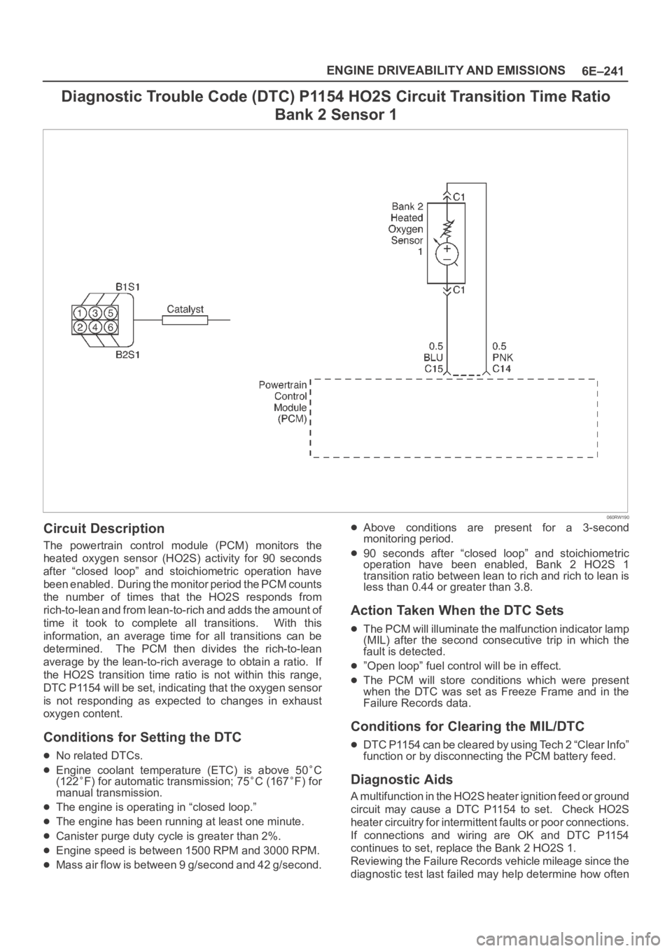
Diagnostic Trouble Code (DTC) P1154 HO2S Circuit Transition Time Ratio
Bank 2 Sensor 1
060RW190
Circuit Description
The powertrain control module (PCM) monitors the
heated oxygen sensor (HO2S) activity for 90 seconds
after “closed loop” and stoichiometric operation have
been enabled. During the monitor period the PCM counts
the number of times that the HO2S responds from
rich-to-lean and from lean-to-rich and adds the amount of
time it took to complete all transitions. With this
information, an average time for all transitions can be
determined. The PCM then divides the rich-to-lean
average by the lean-to-rich average to obtain a ratio. If
the HO2S transition time ratio is not within this range,
DTC P1154 will be set, indicating that the oxygen sensor
is not responding as expected to changes in exhaust
oxygen content.
Conditions for Setting the DTC
No related DTCs.
Engine coolant temperature (ETC) is above 50C
(122F) for automatic transmission; 75C (167F) for
manual transmission.
The engine is operating in “closed loop.”
The engine has been running at least one minute.
Canister purge duty cycle is greater than 2%.
Engine speed is between 1500 RPM and 3000 RPM.
Mass air flow is between 9 g/second and 42 g/second.
Above conditions are present for a 3-second
monitoring period.
90 seconds after “closed loop” and stoichiometric
operation have been enabled, Bank 2 HO2S 1
transition ratio between lean to rich and rich to lean is
less than 0.44 or greater than 3.8.
Action Taken When the DTC Sets
The PCM will illuminate the malfunction indicator lamp
(MIL) after the second consecutive trip in which the
fault is detected.
”Open loop” fuel control will be in effect.
The PCM will store conditions which were present
when the DTC was set as Freeze Frame and in the
Failure Records data.
Conditions for Clearing the MIL/DTC
DTC P1154 can be cleared by using Tech 2 “Clear Info”
function or by disconnecting the PCM battery feed.
Diagnostic Aids
A multifunction in the HO2S heater ignition feed or ground
circuit may cause a DTC P1154 to set. Check HO2S
heater circuitry for intermittent faults or poor connections.
If connections and wiring are OK and DTC P1154
continues to set, replace the Bank 2 HO2S 1.
Reviewing the Failure Records vehicle mileage since the
diagnostic test last failed may help determine how often
Page 4906 of 6000
6E–249 ENGINE DRIVEABILITY AND EMISSIONS
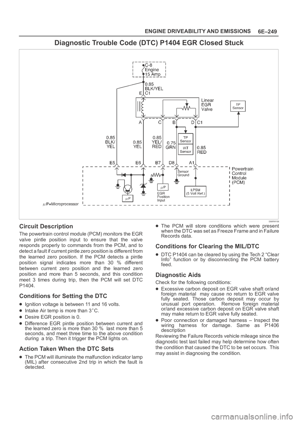
Diagnostic Trouble Code (DTC) P1404 EGR Closed Stuck
D06RW106
Circuit Description
The powertrain control module (PCM) monitors the EGR
valve pintle position input to ensure that the valve
responds properly to commands from the PCM, and to
detect a fault if current pintle zero position is different from
the learned zero position. If the PCM detects a pintle
position signal indicates more than 30 % different
between current zero position and the learned zero
position and more than 5 seconds, and this condition
meet 3 times during trip, then the PCM will set DTC
P1404.
Conditions for Setting the DTC
Ignition voltage is between 11 and 16 volts.
Intake Air temp is more than 3C.
Desire EGR position is 0.
Difference EGR pintle position between current and
the learned zero is more than 30 % last more than 5
seconds, and meet three time to the above condition
during a trip. Then it trigger the PCM lights on.
Action Taken When the DTC Sets
The PCM will illuminate the malfunction indicator lamp
(MIL) after consecutive 2nd trip in which the fault is
detected.
The PCM will store conditions which were present
when the DTC was set as Freeze Frame and in Failure
Records data.
Conditions for Clearing the MIL/DTC
DTC P1404 can be cleared by using the Tech 2 “Clear
Info” function or by disconnecting the PCM battery
feed.
Diagnostic Aids
Check for the following conditions:
Excessive carbon deposit on EGR valve shaft or/and
foreign material may cause no return to EGR valve
fully seated. Those carbon deposit may occur by
unusual port operation. Remove foreign material
or/and excessive carbon deposit on EGR valve shaft
may make return to EGR valve fully seated.
Poor connection or damaged harness – Inspect the
wiring harness for damage. Same as P1406
description
Reviewing the Failure Records vehicle mileage since the
diagnostic test last failed may help determine how often
the condition that caused the DTC to be set occurs. This
may assist in diagnosing the condition.
Page 4908 of 6000
6E–251 ENGINE DRIVEABILITY AND EMISSIONS
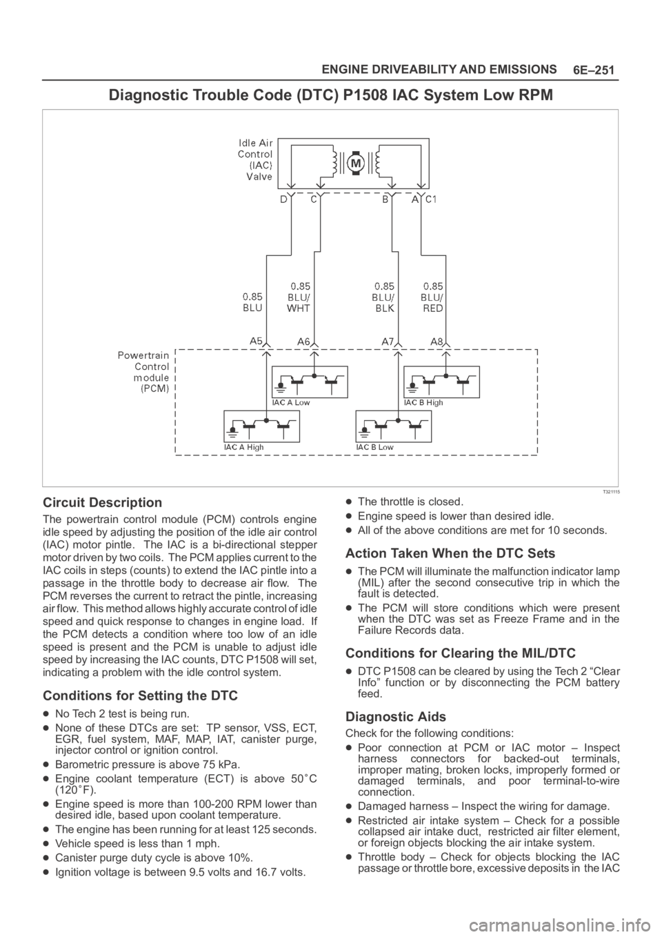
Diagnostic Trouble Code (DTC) P1508 IAC System Low RPM
T321115
Circuit Description
The powertrain control module (PCM) controls engine
idle speed by adjusting the position of the idle air control
(IAC) motor pintle. The IAC is a bi-directional stepper
motor driven by two coils. The PCM applies current to the
IAC coils in steps (counts) to extend the IAC pintle into a
passage in the throttle body to decrease air flow. The
PCM reverses the current to retract the pintle, increasing
air flow. This method allows highly accurate control of idle
speed and quick response to changes in engine load. If
the PCM detects a condition where too low of an idle
speed is present and the PCM is unable to adjust idle
speed by increasing the IAC counts, DTC P1508 will set,
indicating a problem with the idle control system.
Conditions for Setting the DTC
No Tech 2 test is being run.
None of these DTCs are set: TP sensor, VSS, ECT,
EGR, fuel system, MAF, MAP, IAT, canister purge,
injector control or ignition control.
Barometric pressure is above 75 kPa.
Engine coolant temperature (ECT) is above 50C
(120
F).
Engine speed is more than 100-200 RPM lower than
desired idle, based upon coolant temperature.
The engine has been running for at least 125 seconds.
Vehicle speed is less than 1 mph.
Canister purge duty cycle is above 10%.
Ignition voltage is between 9.5 volts and 16.7 volts.
The throttle is closed.
Engine speed is lower than desired idle.
All of the above conditions are met for 10 seconds.
Action Taken When the DTC Sets
The PCM will illuminate the malfunction indicator lamp
(MIL) after the second consecutive trip in which the
fault is detected.
The PCM will store conditions which were present
when the DTC was set as Freeze Frame and in the
Failure Records data.
Conditions for Clearing the MIL/DTC
DTC P1508 can be cleared by using the Tech 2 “Clear
Info” function or by disconnecting the PCM battery
feed.
Diagnostic Aids
Check for the following conditions:
Poor connection at PCM or IAC motor – Inspect
harness connectors for backed-out terminals,
improper mating, broken locks, improperly formed or
damaged terminals, and poor terminal-to-wire
connection.
Damaged harness – Inspect the wiring for damage.
Restricted air intake system – Check for a possible
collapsed air intake duct, restricted air filter element,
or foreign objects blocking the air intake system.
Throttle body – Check for objects blocking the IAC
passage or throttle bore, excessive deposits in the IAC
Page 4911 of 6000
6E–254
ENGINE DRIVEABILITY AND EMISSIONS
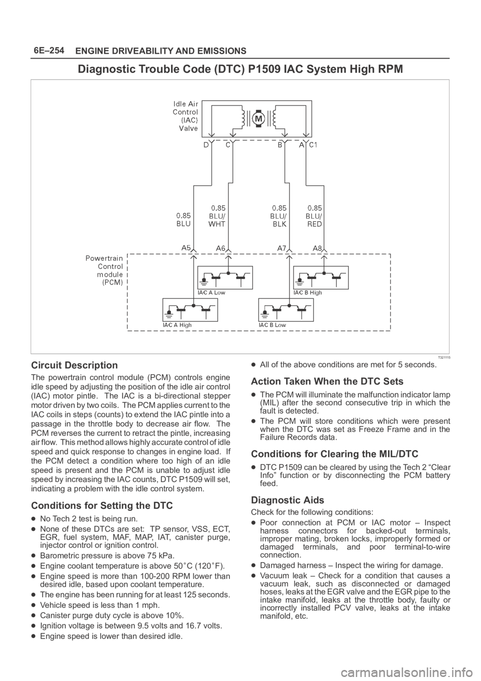
Diagnostic Trouble Code (DTC) P1509 IAC System High RPM
T321115
Circuit Description
The powertrain control module (PCM) controls engine
idle speed by adjusting the position of the idle air control
(IAC) motor pintle. The IAC is a bi-directional stepper
motor driven by two coils. The PCM applies current to the
IAC coils in steps (counts) to extend the IAC pintle into a
passage in the throttle body to decrease air flow. The
PCM reverses the current to retract the pintle, increasing
air flow. This method allows highly accurate control of idle
speed and quick response to changes in engine load. If
the PCM detect a condition where too high of an idle
speed is present and the PCM is unable to adjust idle
speed by increasing the IAC counts, DTC P1509 will set,
indicating a problem with the idle control system.
Conditions for Setting the DTC
No Tech 2 test is being run.
None of these DTCs are set: TP sensor, VSS, ECT,
EGR, fuel system, MAF, MAP, IAT, canister purge,
injector control or ignition control.
Barometric pressure is above 75 kPa.
Engine coolant temperature is above 50C (120F).
Engine speed is more than 100-200 RPM lower than
desired idle, based upon coolant temperature.
The engine has been running for at least 125 seconds.
Vehicle speed is less than 1 mph.
Canister purge duty cycle is above 10%.
Ignition voltage is between 9.5 volts and 16.7 volts.
Engine speed is lower than desired idle.
All of the above conditions are met for 5 seconds.
Action Taken When the DTC Sets
The PCM will illuminate the malfunction indicator lamp
(MIL) after the second consecutive trip in which the
fault is detected.
The PCM will store conditions which were present
when the DTC was set as Freeze Frame and in the
Failure Records data.
Conditions for Clearing the MIL/DTC
DTC P1509 can be cleared by using the Tech 2 “Clear
Info” function or by disconnecting the PCM battery
feed.
Diagnostic Aids
Check for the following conditions:
Poor connection at PCM or IAC motor – Inspect
harness connectors for backed-out terminals,
improper mating, broken locks, improperly formed or
damaged terminals, and poor terminal-to-wire
connection.
Damaged harness – Inspect the wiring for damage.
Vacuum leak – Check for a condition that causes a
vacuum leak, such as disconnected or damaged
h o s e s , l e a k s a t t h e E G R v a l v e a n d t h e E G R p i p e t o t h e
intake manifold, leaks at the throttle body, faulty or
incorrectly installed PCV valve, leaks at the intake
manifold, etc.
Page 4922 of 6000
6E–265 ENGINE DRIVEABILITY AND EMISSIONS
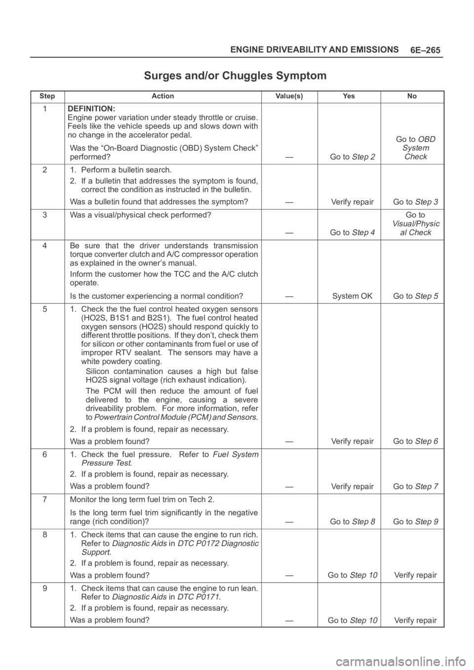
Surges and/or Chuggles Symptom
StepActionVa l u e ( s )Ye sNo
1DEFINITION:
Engine power variation under steady throttle or cruise.
Feels like the vehicle speeds up and slows down with
no change in the accelerator pedal.
Was the “On-Board Diagnostic (OBD) System Check”
performed?
—Go to Step 2
Go to OBD
System
Check
21. Perform a bulletin search.
2. If a bulletin that addresses the symptom is found,
correct the condition as instructed in the bulletin.
Was a bulletin found that addresses the symptom?
—Verify repairGo to Step 3
3Was a visual/physical check performed?
—Go to Step 4
Go to
Visual/Physic
al Check
4Be sure that the driver understands transmission
torque converter clutch and A/C compressor operation
as explained in the owner’s manual.
Inform the customer how the TCC and the A/C clutch
operate.
Is the customer experiencing a normal condition?
—System OKGo to Step 5
51. Check the the fuel control heated oxygen sensors
(HO2S, B1S1 and B2S1). The fuel control heated
oxygen sensors (HO2S) should respond quickly to
different throttle positions. If they don’t, check them
for silicon or other contaminants from fuel or use of
improper RTV sealant. The sensors may have a
white powdery coating.
Silicon contamination causes a high but false
HO2S signal voltage (rich exhaust indication).
The PCM will then reduce the amount of fuel
delivered to the engine, causing a severe
driveability problem. For more information, refer
to
Powertrain Control Module (PCM) and Sensors.
2. If a problem is found, repair as necessary.
Was a problem found?
—Verify repairGo to Step 6
61. Check the fuel pressure. Refer to Fuel System
Pressure Test
.
2. If a problem is found, repair as necessary.
Was a problem found?
—Verify repairGo to Step 7
7Monitor the long term fuel trim on Tech 2.
Is the long term fuel trim significantly in the negative
range (rich condition)?
—Go to Step 8Go to Step 9
81. Check items that can cause the engine to run rich.
Refer to
Diagnostic Aids in DTC P0172 Diagnostic
Support
.
2. If a problem is found, repair as necessary.
Was a problem found?
—Go to Step 10Verify repair
91. Check items that can cause the engine to run lean.
Refer to
Diagnostic Aids in DTC P0171.
2. If a problem is found, repair as necessary.
Was a problem found?
—Go to Step 10Verify repair
Page 4942 of 6000
6E–285 ENGINE DRIVEABILITY AND EMISSIONS
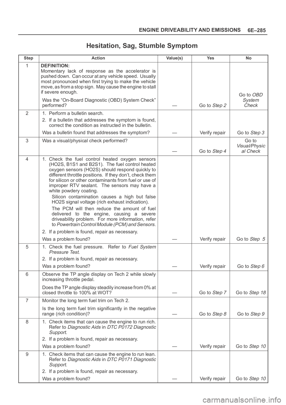
Hesitation, Sag, Stumble Symptom
StepActionVa l u e ( s )Ye sNo
1DEFINITION:
Momentary lack of response as the accelerator is
pushed down. Can occur at any vehicle speed. Usually
most pronounced when first trying to make the vehicle
move, as from a stop sign. May cause the engine to stall
if severe enough.
Was the “On-Board Diagnostic (OBD) System Check”
performed?
—Go to Step 2
Go to OBD
System
Check
21. Perform a bulletin search.
2. If a bulletin that addresses the symptom is found,
correct the condition as instructed in the bulletin.
Was a bulletin found that addresses the symptom?
—Verify repairGo to Step 3
3Was a visual/physical check performed?
—Go to Step 4
Go to
Visual/Physic
al Check
41. Check the fuel control heated oxygen sensors
(HO2S, B1S1 and B2S1). The fuel control heated
oxygen sensors (HO2S) should respond quickly to
different throttle positions. If they don’t, check them
for silicon or other contaminants from fuel or use of
improper RTV sealant. The sensors may have a
white powdery coating.
Silicon contamination causes a high but false
HO2S signal voltage (rich exhaust indication).
The PCM will then reduce the amount of fuel
delivered to the engine, causing a severe
driveability problem. For more information, refer
to
Powertrain Control Module (PCM) and Sensors.
2. If a problem is found, repair as necessary.
Was a problem found?
—Verify repairGo to Step 5
51. Check the fuel pressure. Refer to Fuel System
Pressure Test.
2. If a problem is found, repair as necessary.
Was a problem found?
—Verify repairGo to Step 6
6Observe the TP angle display on Tech 2 while slowly
increasing throttle pedal.
Does the TP angle display steadily increase from 0% at
closed throttle to 100% at WOT?
—Go to Step 7Go to Step 18
7Monitor the long term fuel trim on Tech 2.
Is the long term fuel trim significantly in the negative
range (rich condition)?
—Go to Step 8Go to Step 9
81. Check items that can cause the engine to run rich.
Refer to
Diagnostic Aids in DTC P0172 Diagnostic
Support
.
2. If a problem is found, repair as necessary.
Was a problem found?
—Verify repairGo to Step 10
91. Check items that can cause the engine to run lean.
Refer to
Diagnostic Aids in DTC P0171 Diagnostic
Support
.
2. If a problem is found, repair as necessary.
Was a problem found?
—Verify repairGo to Step 10
Page 4995 of 6000
6E–338
ENGINE DRIVEABILITY AND EMISSIONS
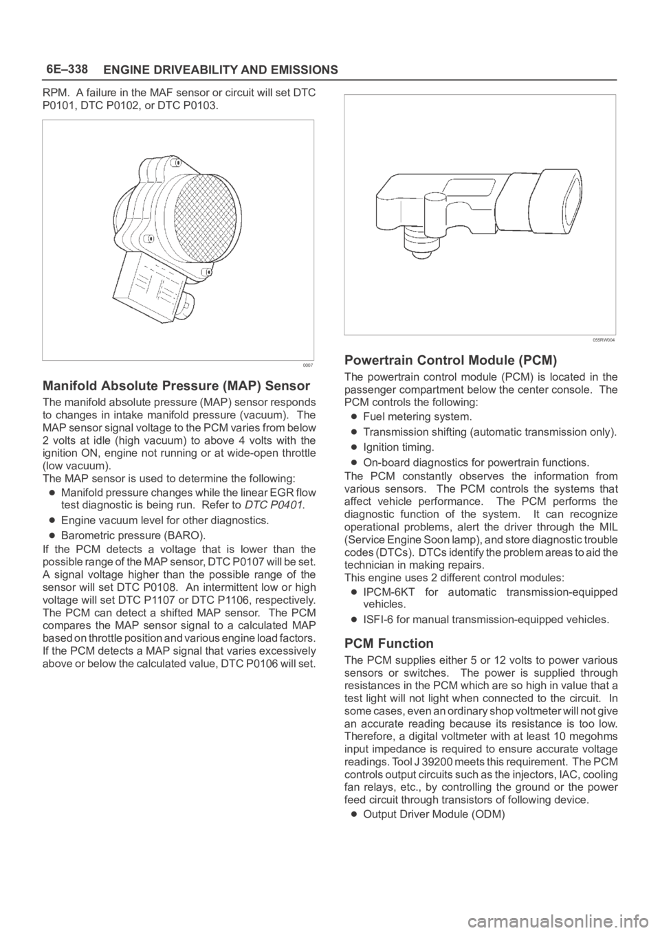
RPM. A failure in the MAF sensor or circuit will set DTC
P0101, DTC P0102, or DTC P0103.
0007
Manifold Absolute Pressure (MAP) Sensor
The manifold absolute pressure (MAP) sensor responds
to changes in intake manifold pressure (vacuum). The
MAP sensor signal voltage to the PCM varies from below
2 volts at idle (high vacuum) to above 4 volts with the
ignition ON, engine not running or at wide-open throttle
(low vacuum).
The MAP sensor is used to determine the following:
Manifold pressure changes while the linear EGR flow
test diagnostic is being run. Refer to
DTC P0401.
Engine vacuum level for other diagnostics.
Barometric pressure (BARO).
If the PCM detects a voltage that is lower than the
possible range of the MAP sensor, DTC P0107 will be set.
A signal voltage higher than the possible range of the
sensor will set DTC P0108. An intermittent low or high
voltage will set DTC P1107 or DTC P1106, respectively.
The PCM can detect a shifted MAP sensor. The PCM
compares the MAP sensor signal to a calculated MAP
based on throttle position and various engine load factors.
If the PCM detects a MAP signal that varies excessively
above or below the calculated value, DTC P0106 will set.
055RW004
Powertrain Control Module (PCM)
The powertrain control module (PCM) is located in the
passenger compartment below the center console. The
PCM controls the following:
Fuel metering system.
Transmission shifting (automatic transmission only).
Ignition timing.
On-board diagnostics for powertrain functions.
The PCM constantly observes the information from
various sensors. The PCM controls the systems that
affect vehicle performance. The PCM performs the
diagnostic function of the system. It can recognize
operational problems, alert the driver through the MIL
(Service Engine Soon lamp), and store diagnostic trouble
codes (DTCs). DTCs identify the problem areas to aid the
technician in making repairs.
This engine uses 2 different control modules:
IPCM-6KT for automatic transmission-equipped
vehicles.
ISFI-6 for manual transmission-equipped vehicles.
PCM Function
The PCM supplies either 5 or 12 volts to power various
sensors or switches. The power is supplied through
resistances in the PCM which are so high in value that a
test light will not light when connected to the circuit. In
some cases, even an ordinary shop voltmeter will not give
an accurate reading because its resistance is too low.
Therefore, a digital voltmeter with at least 10 megohms
input impedance is required to ensure accurate voltage
readings. Tool J 39200 meets this requirement. The PCM
controls output circuits such as the injectors, IAC, cooling
fan relays, etc., by controlling the ground or the power
feed circuit through transistors of following device.
Output Driver Module (ODM)