1998 OPEL FRONTERA ESP
[x] Cancel search: ESPPage 4549 of 6000
6A–53
ENGINE MECHANICAL
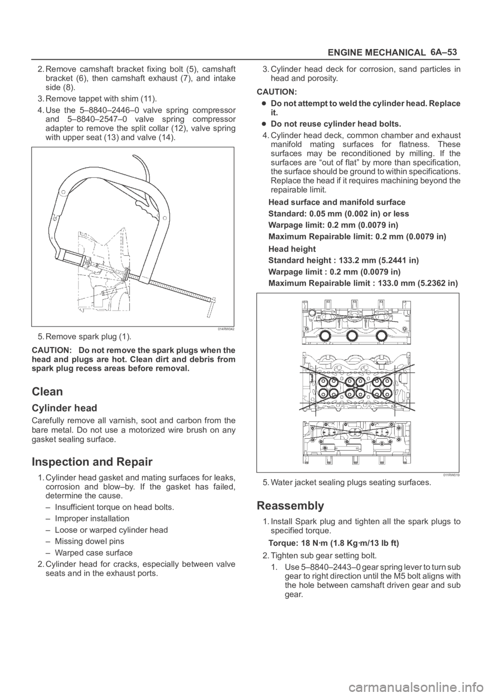
2. Remove camshaft bracket fixing bolt (5), camshaft
bracket (6), then camshaft exhaust (7), and intake
side (8).
3. Remove tappet with shim (11).
4. Use the 5–8840–2446–0 valve spring compressor
and 5–8840–2547–0 valve spring compressor
adapter to remove the split collar (12), valve spring
with upper seat (13) and valve (14).
014RW042
5. Remove spark plug (1).
CAUTION: Do not remove the spark plugs when the
head and plugs are hot. Clean dirt and debris from
spark plug recess areas before removal.
Clean
Cylinder head
Carefully remove all varnish, soot and carbon from the
bare metal. Do not use a motorized wire brush on any
gasket sealing surface.
Inspection and Repair
1. Cylinder head gasket and mating surfaces for leaks,
corrosion and blow–by. If the gasket has failed,
determine the cause.
– Insufficient torque on head bolts.
– Improper installation
– Loose or warped cylinder head
– Missing dowel pins
– Warped case surface
2. Cylinder head for cracks, especially between valve
seats and in the exhaust ports.3. Cylinder head deck for corrosion, sand particles in
head and porosity.
CAUTION:
Do not attempt to weld the cylinder head. Replace
it.
Do not reuse cylinder head bolts.
4. Cylinder head deck, common chamber and exhaust
manifold mating surfaces for flatness. These
surfaces may be reconditioned by milling. If the
surfaces are “out of flat” by more than specification,
the surface should be ground to within specifications.
Replace the head if it requires machining beyond the
repairable limit.
Head surface and manifold surface
Standard: 0.05 mm (0.002 in) or less
Warpage limit: 0.2 mm (0.0079 in)
Maximum Repairable limit: 0.2 mm (0.0079 in)
Head height
Standard height : 133.2 mm (5.2441 in)
Warpage limit : 0.2 mm (0.0079 in)
Maximum Repairable limit : 133.0 mm (5.2362 in)
011RW019
5. Water jacket sealing plugs seating surfaces.
Reassembly
1. Install Spark plug and tighten all the spark plugs to
specified torque.
Torque: 18 Nꞏm (1.8 Kgꞏm/13 lb ft)
2. Tighten sub gear setting bolt.
1. Use 5–8840–2443–0 gear spring lever to turn sub
gear to right direction until the M5 bolt aligns with
the hole between camshaft driven gear and sub
gear.
Page 4610 of 6000
6C–3
ENGINE FUEL
Adhere to all Notices and Cautions.
All gasoline engines are designed to use only unleaded
gasoline. Unleaded gasoline must be used for proper
emission control system operation.
Its use will also minimize spark plug fouling and extend
engine oil life. Using leaded gasoline can damage the
emission control system and could result in loss of
emission warranty coverage.
All cars are equipped with an Evaporative Emission
Control System. The purpose of the system is to minimize
the escape of fuel vapors to the atmosphere.
Fuel Metering
The Engine Control Module (ECM) is in complete control
of this fuel delivery system during normal driving
conditions.
The intake manifold function, like that of a diesel, is used
only to let air into the engine. The fuel is injected by
separate injectors that are mounted over the intake
manifold.
The Manifold Absolute Pressure (MAP) sensor measures
the changes in the intake manifold pressure which result
from engine load and speed changes, which the MAP
sensor converts to a voltage output.
This sensor generates the voltage to change
corresponding to the flow of the air drawn into the engine.
The changing voltage is transformed into an electric
signal and provided to the ECM.
With receipt of the signals sent from the MAP sensor,
Intake Air Temperature sensor and others, the ECM
determines an appropriate fuel injection pulse width
feeding such information to the fuel injector valves to
effect an appropriate air/fuel ratio.
The Multiport Fuel Injection system utilizes an injection
system where the injectors turn on at every crankshaft
re vol u tion . Th e EC M con tro ls t he in je cto r on tim e so t ha t
the correct amount of fuel is metered depending on
driving conditions.
Two interchangeable “O” rings are used on the injector
that must be replaced when the injectors are removed.
The fuel rail is attached to the top of the intake manifold
and supplies fuel to all the injectors.
Fuel is recirculated through the rail continually while the
engine is running. This removes air and vapors from the
fuel as well as keeping the fuel cool during hot weather
operation.
The fuel pressure control valve that is mounted on the fuel
rail maintains a pressure differential across the injectors
under all operating conditions. It is accomplished by
controlling the amount of fuel that is recirculated back to
the fuel tank based on engine demand.
See Section “Driveability and Emission” for more
information and diagnosis.
Page 4627 of 6000
6D2–2
IGNITION SYSTEM
General Description
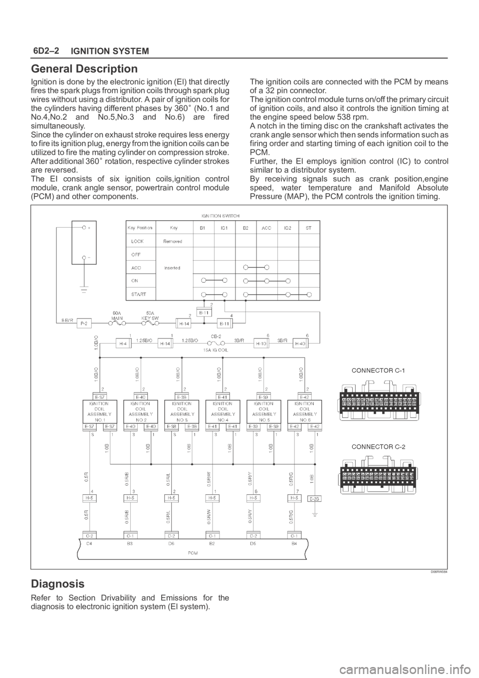
Ignition is done by the electronic ignition (El) that directly
fires the spark plugs from ignition coils through spark plug
wires without using a distributor. A pair of ignition coils for
the cylinders having different phases by 360
(No.1 and
No.4,No.2 and No.5,No.3 and No.6) are fired
simultaneously.
Since the cylinder on exhaust stroke requires less energy
to fire its ignition plug, energy from the ignition coils can be
utilized to fire the mating cylinder on compression stroke.
After additional 360
rotation, respective cylinder strokes
are reversed.
The EI consists of six ignition coils,ignition control
module, crank angle sensor, powertrain control module
(PCM) and other components.The ignition coils are connected with the PCM by means
of a 32 pin connector.
The ignition control module turns on/off the primary circuit
of ignition coils, and also it controls the ignition timing at
the engine speed below 538 rpm.
A notch in the timing disc on the crankshaft activates the
crank angle sensor which then sends information such as
firing order and starting timing of each ignition coil to the
PCM.
Further, the El employs ignition control (IC) to control
similar to a distributor system.
By receiving signals such as crank position,engine
speed, water temperature and Manifold Absolute
Pressure (MAP), the PCM controls the ignition timing.
D06RW084
Diagnosis
Refer to Section Drivability and Emissions for the
diagnosis to electronic ignition system (El system).
Page 4655 of 6000
6D3–24STARTING AND CHARGING SYSTEM
Stator Coil
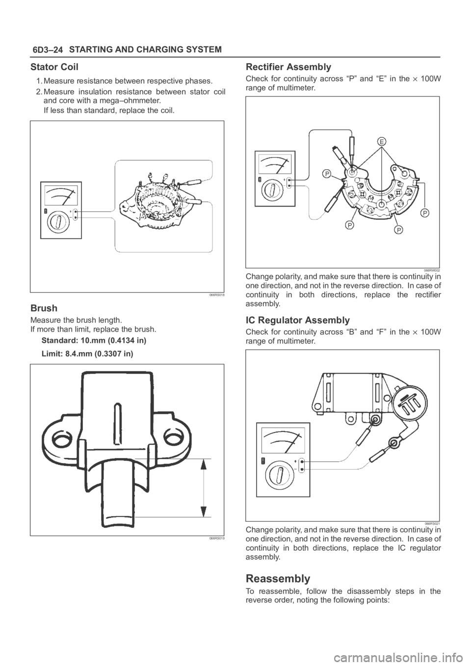
1. Measure resistance between respective phases.
2. Measure insulation resistance between stator coil
and core with a mega–ohmmeter.
If less than standard, replace the coil.
066RS018
Brush
Measure the brush length.
If more than limit, replace the brush.
Standard: 10.mm (0.4134 in)
Limit: 8.4.mm (0.3307 in)
066RS019
Rectifier Assembly
Check for continuity across “P” and “E” in the 100W
range of multimeter.
066RW002Change polarity, and make sure that there is continuity in
one direction, and not in the reverse direction. In case of
continuity in both directions, replace the rectifier
assembly.
IC Regulator Assembly
Check for continuity across “B” and “F” in the 100W
range of multimeter.
066RS021Change polarity, and make sure that there is continuity in
one direction, and not in the reverse direction. In case of
continuity in both directions, replace the IC regulator
assembly.
Reassembly
To reassemble, follow the disassembly steps in the
reverse order, noting the following points:
Page 4679 of 6000
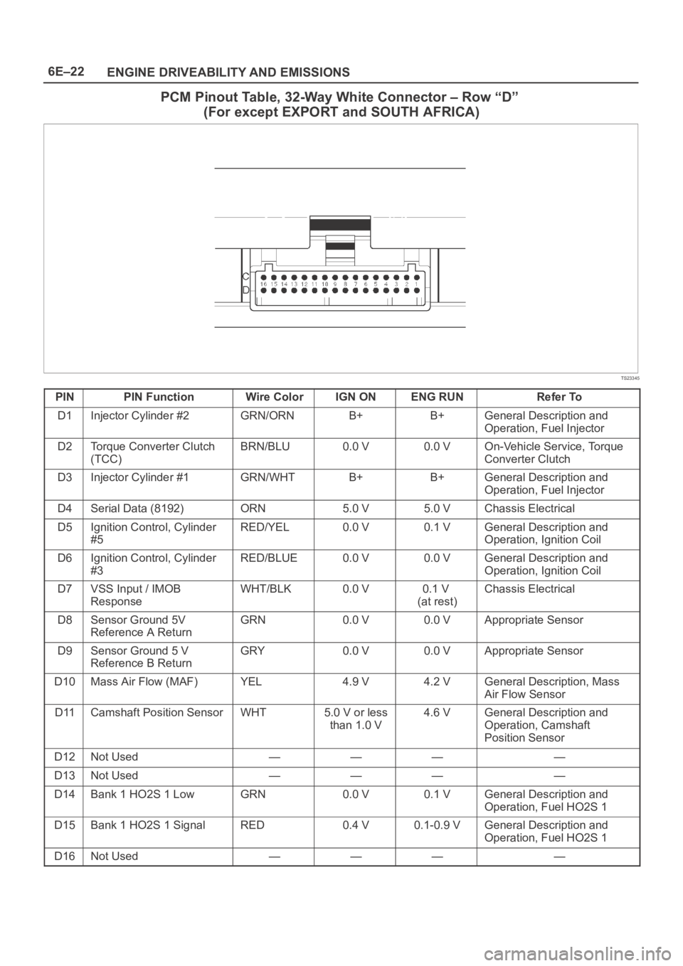
6E–22
ENGINE DRIVEABILITY AND EMISSIONS
PCM Pinout Table, 32-Way White Connector – Row “D”
(For except EXPORT and SOUTH AFRICA)
TS23345
PINPIN FunctionWire ColorIGN ONENG RUNRefer To
D1Injector Cylinder #2GRN/ORNB+B+General Description and
Operation, Fuel Injector
D2Torque Converter Clutch
(TCC)BRN/BLU0.0 V0.0 VOn-Vehicle Service, Torque
Converter Clutch
D3Injector Cylinder #1GRN/WHTB+B+General Description and
Operation, Fuel Injector
D4Serial Data (8192)ORN5.0 V5.0 VChassis Electrical
D5Ignition Control, Cylinder
#5RED/YEL0.0 V0.1 VGeneral Description and
Operation, Ignition Coil
D6Ignition Control, Cylinder
#3RED/BLUE0.0 V0.0 VGeneral Description and
Operation, Ignition Coil
D7VSS Input / IMOB
ResponseWHT/BLK0.0 V0.1 V
(at rest)Chassis Electrical
D8Sensor Ground 5V
Reference A ReturnGRN0.0 V0.0 VAppropriate Sensor
D9Sensor Ground 5 V
Reference B ReturnGRY0.0 V0.0 VAppropriate Sensor
D10Mass Air Flow (MAF)YEL4.9 V4.2 VGeneral Description, Mass
Air Flow Sensor
D11Camshaft Position SensorWHT5.0 V or less
than 1.0 V4.6 VGeneral Description and
Operation, Camshaft
Position Sensor
D12Not Used————
D13Not Used————
D14Bank 1 HO2S 1 LowGRN0.0 V0.1 VGeneral Description and
Operation, Fuel HO2S 1
D15Bank 1 HO2S 1 SignalRED0.4 V0.1-0.9 VGeneral Description and
Operation, Fuel HO2S 1
D16Not Used————
Page 4680 of 6000
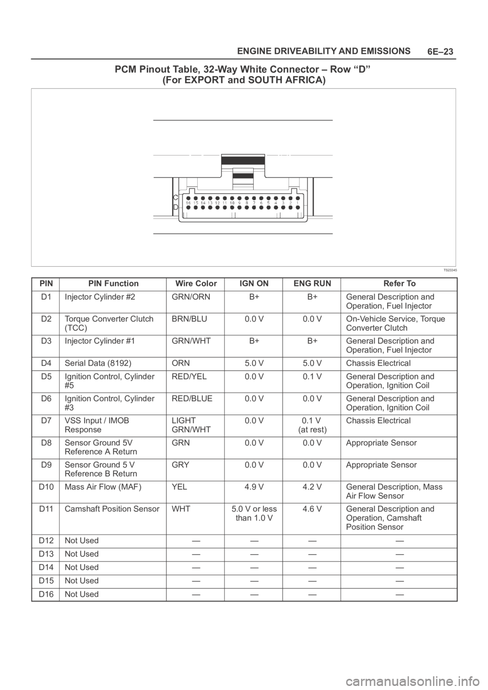
6E–23 ENGINE DRIVEABILITY AND EMISSIONS
PCM Pinout Table, 32-Way White Connector – Row “D”
(For EXPORT and SOUTH AFRICA)
TS23345
PINPIN FunctionWire ColorIGN ONENG RUNRefer To
D1Injector Cylinder #2GRN/ORNB+B+General Description and
Operation, Fuel Injector
D2Torque Converter Clutch
(TCC)BRN/BLU0.0 V0.0 VOn-Vehicle Service, Torque
Converter Clutch
D3Injector Cylinder #1GRN/WHTB+B+General Description and
Operation, Fuel Injector
D4Serial Data (8192)ORN5.0 V5.0 VChassis Electrical
D5Ignition Control, Cylinder
#5RED/YEL0.0 V0.1 VGeneral Description and
Operation, Ignition Coil
D6Ignition Control, Cylinder
#3RED/BLUE0.0 V0.0 VGeneral Description and
Operation, Ignition Coil
D7VSS Input / IMOB
ResponseLIGHT
GRN/WHT0.0 V0.1 V
(at rest)Chassis Electrical
D8Sensor Ground 5V
Reference A ReturnGRN0.0 V0.0 VAppropriate Sensor
D9Sensor Ground 5 V
Reference B ReturnGRY0.0 V0.0 VAppropriate Sensor
D10Mass Air Flow (MAF)YEL4.9 V4.2 VGeneral Description, Mass
Air Flow Sensor
D11Camshaft Position SensorWHT5.0 V or less
than 1.0 V4.6 VGeneral Description and
Operation, Camshaft
Position Sensor
D12Not Used————
D13Not Used————
D14Not Used————
D15Not Used————
D16Not Used————
Page 4696 of 6000
6E–39 ENGINE DRIVEABILITY AND EMISSIONS
The data displayed on the other Tech 2 will appear the
same, with some exceptions. Some Tech 2s will only be
able to display certain vehicle parameters as values that
are a coded representation of the true or actual value. For
more information on this system of coding, refer to
Decimal/Binary/Hexadecimal Conversions. On this
vehicle Tech 2 displays the actual values for vehicle
parameters. It will not be necessary to perform any
conversions from coded values to actual values.
On-Board Diagnostic (OBD)
On-Board Diagnostic Tests
A diagnostic test is a series of steps, the result of which is
a pass or fail reported to the diagnostic executive. When
a diagnostic test reports a pass result, the diagnostic
executive records the following data:
The diagnostic test has been completed since the last
ignition cycle.
The diagnostic test has passed during the current
ignition cycle.
The fault identified by the diagnostic test is not
currently active.
W h e n a d i a g n o s t i c t e s t r e p o r t s a fail result, the diagnostic
executive records the following data:
The diagnostic test has been completed since the last
ignition cycle.
The fault identified by the diagnostic test is currently
active.
The fault has been active during this ignition cycle.
The operating conditions at the time of the failure.
Remember, a fuel trim DTC may be triggered by a list of
vehicle faults. Make use of all information available (other
DTCs stored, rich or lean condition, etc.) when
diagnosing a fuel trim fault.
Comprehensive Component Monitor
Diagnostic Operation
Input Components:
Input components are monitored for circuit continuity and
out-of-range values. This includes rationality checking.
Rationality checking refers to indicating a fault when the
signal from a sensor does not seem reasonable, i.e.
Throttle Position (TP) sensor that indicates high throttle
position at low engine loads or MAP voltage. Input
components may include, but are not limited to the
following sensors:
Vehicle Speed Sensor (VSS)
Crankshaft Position (CKP) sensor
Knock Sensor (KS)
Throttle Position (TP) sensor
Engine Coolant Temperature (ECT) sensor
Camshaft Position (CMP) sensor
Manifold Absolute Pressure (MAP) sensor
Mass Air Flow (MAF) sensorIn addition to the circuit continuity and rationality check,
the ECT sensor is monitored for its ability to achieve a
steady state temperature to enable closed loop fuel
control.
Output Components:
Output components are diagnosed for proper response to
control module commands. Components where
functional monitoring is not feasible will be monitored for
circuit continuity and out-of-range values if applicable.
Output components to be monitored include, but are not
limited to, the following circuits:
Idle Air Control (IAC) Motor
Electronic Transmission controls
A/C relays
Cooling fan relay
VSS output
MIL control
Cruise control inhibit
Refer to PCM and Sensors in General Descriptions.
Passive and Active Diagnostic Tests
A passive test is a diagnostic test which simply monitors a
vehicle system or component. Conversely, an active test,
actually takes some sort of action when performing
diagnostic functions, often in response to a failed passive
test. For example, the EGR diagnostic active test will
force the EGR valve open during closed throttle decel
and/or force the EGR valve closed during a steady state.
Either action should result in a change in manifold
pressure.
Intrusive Diagnostic Tests
This is any on-board test run by the Diagnostic
Management System which may have an effect on
vehicle performance or emission levels.
Warm-Up Cycle
A warm-up cycle means that engine at temperature must
reach a minimum of 70
C (160F) and rise at least 22C
(40
F) over the course of a trip.
Freeze Frame
Freeze Frame is an element of the Diagnostic
Management System which stores various vehicle
information at the moment an emissions-related fault is
stored in memory and when the MIL is commanded on.
These data can help to identify the cause of a fault. Refer
to
Storing And Erasing Freeze Fame Data for more
detailed information.
Failure Records
Failure Records data is an enhancement of the OBD
Freeze Frame feature. Failure Records store the same
vehicle information as does Freeze Frame, but it will store
that information for any fault which is stored in on-board
memory, while Freeze Frame stores information only for
emission-related faults that command the MIL on.
Page 4697 of 6000
6E–40
ENGINE DRIVEABILITY AND EMISSIONS
Common OBD Terms
Diagnostic
When used as a noun, the word diagnostic refers to any
on-board test run by the vehicle’s Diagnostic
Management System. A diagnostic is simply a test run on
a system or component to determine if the system or
component is operating according to specification. There
are many diagnostics, shown in the following list:
Oxygen sensors
Oxygen sensor heaters
EGR
Catalyst monitoring
Enable Criteria
The term “enable criteria” is engineering language for the
conditions necessary for a given diagnostic test to run.
Each diagnostic has a specific list of conditions which
must be met before the diagnostic will run. “Enable
criteria” is another way of saying “conditions required”.
The enable criteria for each diagnostic is listed on the first
page of the DTC description under the heading
“Conditions for Setting the DTC”. Enable criteria varies
with each diagnostic, and typically includes, but is not
limited to the following items:
engine speed
vehicle speed
ECT
MAF/MAP
barometric pressure
IAT
TP
fuel trim
TCC enabled
A/C on
Tr i p
Technically, a trip is a key on-run-key off cycle in which all
the enable criteria for a given diagnostic are met, allowing
the diagnostic to run. Unfortunately, this concept is not
quite that simple. A trip is official when all the enable
criteria for a given diagnostic are met. But because the
enable criteria vary from one diagnostic to another, the
definition of trip varies as well. Some diagnostic are run
when the vehicle is at operating temperature, some when
the vehicle first start up; some require that the vehicle be
cruising at a steady highway speed, some run only when
the vehicle is idle; some diagnostics function with the
TCC disables. Some run only immediately following a
cold engine start-up.
A trip then, is defined as a key on-run-key off cycle in
which the vehicle was operated in such a way as to satisfy
the enables criteria for a given diagnostic, and this
diagnostic will consider this cycle to be one trip. However,
another diagnostic with a different set of enable criteria
(which were not met) during this driving event, would not
consider it a trip. No trip will occur for that particular
diagnostic until the vehicle is driven in such a way as to
meet all the enable criteria.
The Diagnostic Executive
The Diagnostic Executive is a unique segment of
software which is designed to coordinate and prioritize
the diagnostic procedures as well as define the protocol
for recording and displaying their results. The main
responsibilities of the Diagnostic Executive are listed as
following:
Commanding the MIL (“Check Engine” lamp) on and
off
DTC logging and clearing
Freeze Frame data for the first emission related DTC
recorded
Non-emission related Service Lamp (future)
Operating conditions Failure Records buffer, (the
number of records will vary)
Current status information on each diagnostic
The Diagnostic Executive records DTCs and turns on the
MIL when emission-related faults occur. It can also turn
off the MIL if the conditions cease which caused the DTC
to set.
Diagnostic Information
The diagnostic charts and functional checks are designed
to locate a faulty circuit or component through a process
of logical decisions. The charts are prepared with the
requirement that the vehicle functioned correctly at the
time of assembly and that there are not multiple faults
present.
There is a continuous self-diagnosis on certain control
functions. This diagnostic capability is complemented by
the diagnostic procedures contained in this manual. The
language of communicating the source of the malfunction
is a system of diagnostic trouble codes. When a
malfunction is detected by the control module, a
diagnostic trouble code is set and the Malfunction
Indicator Lamp (MIL) (“Check Engine” lamp) is
illuminated.
Malfunction Indicator Lamp (MIL)
The Malfunction Indicator Lamp (MIL) looks the same as
the MIL you are already familiar with (“Check Engine”
lamp). However, OBD requires that the it illuminate under
a strict set of guide lines.
Basically, the MIL is turned on when the PCM detects a
DTC that will impact the vehicle emissions.
The MIL is under the control of the Diagnostic Executive.
The MIL will be turned on if an emissions-related
diagnostic test indicates a malfunction has occurred. It
will stay on until the system or component passes the
same test, for three consecutive trips, with no
emissionsrelated faults.
Extinguishing the MIL
When the MIL is on, the Diagnostic Executive will turn off
the MIL after
three consecutive trips that a “test passed”
has been reported for the diagnostic test that originally
caused the MIL to illuminate.
Although the MIL has been turned off, the DTC will remain
in the PCM memory (both Freeze Frame and Failure
Records) until
forty(40) warm-up cycles after no faults
have been completed.