Page 558 of 6000

4B1–25 DRIVE LINE CONTROL SYSTEM (SHIFT ON THE FLY)
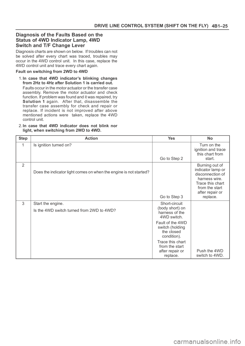
Diagnosis of the Faults Based on the
Status of 4WD Indicator Lamp, 4WD
Switch and T/F Change Lever
Diagnosis charts are shown on below. If troubles can not
be solved after every chart was traced, troubles may
occur in the 4WD control unit. In this case, replace the
4WD control unit and trace every chart again.
Fault on switching from 2WD to 4WD
1.In case that 4WD indicator’s blinking changes
from 2Hz to 4Hz after Solution 1 is carried out.
Faults occur in the motor actuator or the transfer case
assembly. Remove the motor actuator and check
function. If problem was found and it was repaired, try
Solution 1 again. After that, disassemble the
transfer case assembly for check and repair or
replace. If incident is not improved after above
mentioned actions were taken, replace the 4WD
control unit.
2.In case that 4WD indicator does not blink nor
light, when switching from 2WD to 4WD.
Step
ActionYe sNo
1Is ignition turned on?
Go to Step 2
Turn on the
ignition and trace
this chart from
start.
2
Does the indicator light comes on when the engine is not started?
Go to Step 3
Burning out of
indicator lamp or
disconnection of
harness wire.
Trace this chart
from the start
after repair or
replace.
3Start the engine.
Is the 4WD switch turned from 2WD to 4WD?Short-circuit
(body short) on
harness of the
4WD switch.
Fault of the 4WD
switch (holding
the closed
condition).
Trace this chart
from the start
after repair or
replace.
Push the 4WD
switch to 4WD.
Page 563 of 6000

4B1–30
DRIVE LINE CONTROL SYSTEM (SHIFT ON THE FLY)
Front Axle Diagnosis
When the 4WD switch is operated from 4H to 2H,
indicator light does not go out.
Step
ActionYe sNo
1Drive slow 100 — 200m after a few minutes” idling.
Has indicator light gone out?
All right.Go to Step 2
2Jack up front tires.
Does the right side of front wheel rotate when the left side of f r o n t
wheel is rotated?
Go to Step 4Go to Step 3
31. Check the actuator switch.
2. Check the circuit to indicator.
Was a problem found?
Trace this chart
from the start
after repair or
replace.
Disassemble axle
ASM for check.
Trace this chart
from the start
after repair or
replace.
41. Check the VSV valve.
2. Check the circuit to VSV valve.
Was a problem found?Trace this chart
from the start
after repair or
replace.
Go to Step 5
5I s v a c u u m p i p i n g a l l r i g h t ? ( t a n k , h o s e , & p i p e d a m a g e o r t r o u ble)
Go to Step 6
Trace this chart
from the start
after repair or
replace.
6Does actuator work all right?
Trace this chart
from the start.
Disassemble axle
ASM for check.
Trace this chart
from the start
after repair or
replace.
Page 564 of 6000

4B1–31 DRIVE LINE CONTROL SYSTEM (SHIFT ON THE FLY)
When the 4WD switch is operated from 2H to 4H,
indicator light is not actuated.
Step
ActionYe sNo
1Drive slow 100 — 200m after a few minutes” idling.
Has indicator light actuated?
All right.Go to Step 2
2Jack up front tires.
Does not the right side of front wheel rotate when the left side of
front wheel is rotated?
Go to Step 4Go to Step 3
31. Check the actuator switch.
2. Check the circuit to indicator.
Was a problem found?
Trace this chart
from the start
after repair or
replace.
Disassemble axle
ASM for check.
Trace this chart
from the start
after repair or
replace.
41. Check the VSV valve.
2. Check the circuit to VSV valve.
Was a problem found?Trace this chart
from the start
after repair or
replace.
Go to Step 5
5I s v a c u u m p i p i n g a l l r i g h t ? ( t a n k , h o s e , & p i p e d a m a g e o r t r o u ble)
Go to Step 6
Trace this chart
from the start
after repair or
replace.
6Does actuator work all right?
Trace this chart
from the start.
Disassemble axle
ASM for check.
Trace this chart
from the start
after repair or
replace.
Page 583 of 6000
DRIVE LINE CONTROL SYSTEM (TOD) 4B2–12
Diagnosis
General Information Diagnosis
The troubles on TOD are classified into the group that can
be identified by the lighting status of the TOD indicator
lamps and those that can be recognized as abnormal
phenomena of the vehicle by the driver.
The troubles that can be identified by the lighting status of
the TOD indicator lamps are examined by the procedures“Diagnosis from Trouble Codes” and “Trouble Diagnosis
Depending on The Status of TOD indicator”. The troubles
that can be recognized as abnormal phenomena of the
vehicle by the driver are examined by the procedure
“Diagnosis from symptom”.
Self-diagnosis
The control unit has a function of self-diagnosis. If a
trouble occurs in the course of system startup, the control
unit blinks the CHECK lamp and saves the trouble code.
C07RW021
NOTE: If an intermittent fault occurs, the control unit
stops blinking upon removal of the fault. The trouble code
is saved to the control unit.
Page 586 of 6000

4B2–15 DRIVE LINE CONTROL SYSTEM (TOD)
7. Slowly start the vehicle in the 4L mode, and
accelerate to at least 20 km/h. Apply the brake to
completely stop the vehicle.
If the CHECK lamp starts blinking during the test run, read
the trouble codes and give appropriate maintenance
according to the fault diagnostic procedure. If the TOD
indicator lamps are lit abnormally during the run, check
the lighting condition and give appropriate maintenance
according to the fault diagnostic procedure. Even if the
phenomena are not observed, try to reproduce the
abnormal state reported by the customer to the possible
extent.
Post-Repair Check
As long as the starter is not turned off, the TOD indicator
lamps continue blinking even after the failed control unit is
repaired. Therefore, upon completion of repair, be sure to
turn off the starter switch once and then turn on it to
conduct the test run sequence specified in steps 1
through 6 above and check that the TOD indicator lamps
no longer show any faulty status.
Page 595 of 6000
DRIVE LINE CONTROL SYSTEM (TOD) 4B2–24
No.NAMECONTENTS
1VIGPower supply (IG)
2N.CNot used
34WD OUT4WD signal output
4SOL (+)Electromagnetic solenoid
5ADC (+)Axle disconnect output
6LIGHTING SWLighting SW input
7BRAKEBrake SW input
84H SW4H SW input
94L SW4L SW input
10AXEL SWAXEL SW input
11ABS INOperation signal input
12TOD SWTOD SW input
13DIAGSelf-diagnosis input
14D-G MAPD-G MAP recognition input (Only V6 engine)
15Ref.Vehicle speed sensor supply
16N.CNot used
17US/JAPDestination recognition input
18COM (–)Vehicle speed sensor GND
19S-GNDSensor GND
20P-GNDPower GND
21TPSThrottle position sensor
22TECH 2TECH 2 output
23Rer. SigRear vehicle speed sensor input
24Frt. SigFront vehicle speed sensor input
25IND.a4WD disply signal a
26IND.b4WD display signal b
27IND.c4WD display signal c
28IND.AUTOAUTO display output
29IND RrRear display output
30CHECKTOD warning lamp
Page 597 of 6000

DRIVE LINE CONTROL SYSTEM (TOD) 4B2–26
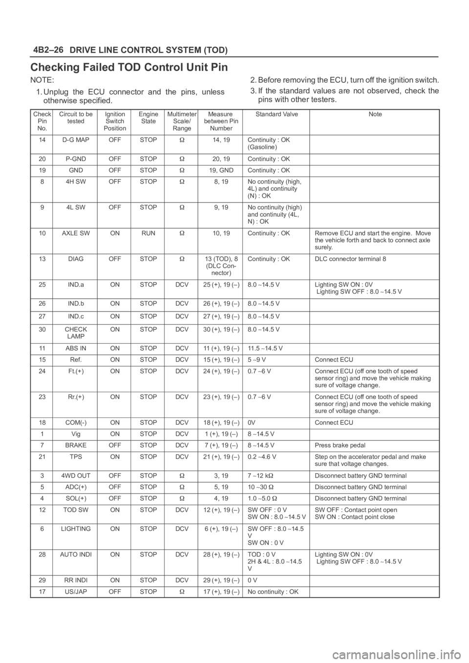
Checking Failed TOD Control Unit Pin
NOTE:
1. Unplug the ECU connector and the pins, unless
otherwise specified.2. Before removing the ECU, turn off the ignition switch.
3. If the standard values are not observed, check the
pins with other testers.
Check
Pin
No.Circuit to be
testedIgnition
Switch
PositionEngine
StateMultimeter
Scale/
RangeMeasure
between Pin
NumberStandard ValveNote
14D-G MAPOFFSTOP14, 19Continuity : OK
(Gasoline)
20P-GNDOFFSTOP20, 19Continuity : OK
19GNDOFFSTOP19, GNDContinuity : OK
84H SWOFFSTOP8, 19No continuity (high,
4L) and continuity
(N) : OK
94L SWOFFSTOP9, 19No continuity (high)
and continuity (4L,
N) : OK
10AXLE SWONRUN10, 19Continuity : OKRemove ECU and start the engine. Move
the vehicle forth and back to connect axle
surely.
13DIAGOFFSTOP13 (TOD), 8
(DLC Con-
nector)Continuity : OKDLC connector terminal 8
25IND.aONSTOPDCV25 (+), 19 (–)8.0 14.5 VLighting SW ON : 0V
Lighting SW OFF : 8.0 14.5 V
26IND.bONSTOPDCV26 (+), 19 (–)8.0 14.5 V
27IND.cONSTOPDCV27 (+), 19 (–)8.0 14.5 V
30CHECK
LAMPONSTOPDCV30 (+), 19 (–)8.0 14.5 V
11ABS INONSTOPDCV11 (+), 19 (–)11 . 5 14.5 V
15Ref.ONSTOPDCV15 (+), 19 (–)5 9 VConnect ECU
24Ft.(+)ONSTOPDCV24 (+), 19 (–)0.7 6 VConnect ECU (off one tooth of speed
sensor ring) and move the vehicle making
sure of voltage change.
23Rr.(+)ONSTOPDCV23 (+), 19 (–)0.7 6 VConnect ECU (off one tooth of speed
sensor ring) and move the vehicle making
sure of voltage change.
18COM(-)ONSTOPDCV18 (+), 19 (–)0VConnect ECU
1VigONSTOPDCV1 (+), 19 (–)8 14.5 V
7BRAKEOFFSTOPDCV7 (+), 19 (–)8 14.5 VPress brake pedal
21TPSONSTOPDCV21 (+), 19 (–)0.2 4.6 VStep on the accelerator pedal and make
sure that voltage changes.
34WD OUTOFFSTOP3, 197 12 kDisconnect battery GND terminal
5ADC(+)OFFSTOP5, 1910 30 Disconnect battery GND terminal
4SOL(+)OFFSTOP4, 191.0 5.0 Disconnect battery GND terminal
12TOD SWONSTOPDCV12 (+), 19 (–)SW OFF : 0 V
SW ON : 8.0 14.5 VSW OFF : Contact point open
SW ON : Contact point close
6LIGHTINGONSTOPDCV6 (+), 19 (–)SW OFF : 8.0 14.5
V
SW ON : 0 V
28AUTO INDIONSTOPDCV28 (+), 19 (–)TOD : 0 V
2H & 4L : 8.0 14.5
VLighting SW ON : 0V
Lighting SW OFF : 8.0 14.5 V
29RR INDIONSTOPDCV29 (+), 19 (–)0 V
17US/JAPOFFSTOP17 (+), 19 (–)No continuity : OK
Page 629 of 6000
DRIVE LINE CONTROL SYSTEM (TOD) 4B2–58
Trouble Diagnosis Depending on The
Status of TOD Indicator
Functional check with TOD indicator light is conducted
prior to check on Charts A–H.
After the starter is switched on, check and see if the
status has become as tabulated below.
C07RW012
If the status is as tabulated above, there is no
problem. If not as tabulated above, inspect the
harness.