1998 OPEL FRONTERA light
[x] Cancel search: lightPage 960 of 6000
6A–4
ENGINE MECHANICAL
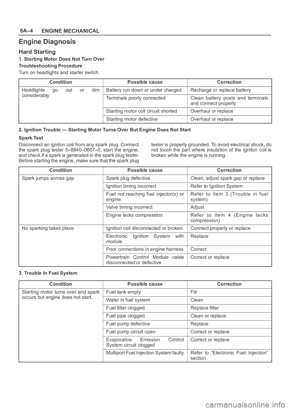
Engine Diagnosis
Hard Starting
1. Starting Motor Does Not Turn Over
Troubleshooting Procedure
Turn on headlights and starter switch.
Condition
Possible causeCorrection
Headlights go out or dim
considerably
Battery run down or under chargedRecharge or replace battery
considerablyTerminals poorly connectedClean battery posts and terminals
and connect properly
Starting motor coil circuit shortedOverhaul or replace
Starting motor defectiveOverhaul or replace
2. Ignition Trouble — Starting Motor Turns Over But Engine Does Not Start
Spark Test
Disconnect an igniton coil from any spark plug. Connect
the spark plug tester 5–8840–0607–0, start the engine,
a n d c h e c k i f a s p a r k i s g e n e r a t e d in t h e s p a r k p l u g t e s t e r.
Before starting the engine, make sure that the spark plugtester is properly grounded. To avoid electrical shock, do
not touch the part where insulation of the igniton coil is
broken while the engine is running.
Condition
Possible causeCorrection
Spark jumps across gapSpark plug defectiveClean, adjust spark gap or replace
Ignition timing incorrectRefer to Ignition System
Fuel not reaching fuel injector(s) or
engineRefer to item 3 (Trouble in fuel
system)
Valve timing incorrectAdjust
Engine lacks compressionRefer to item 4 (Engine lacks
compression)
No sparking takes placeIgnition coil disconnected or brokenConnect properly or replace
Electronic Ignition System with
moduleReplace
Poor connections in engine harnessCorrect
Powertrain Control Module cable
disconnected or defectiveCorrect or replace
3. Trouble In Fuel System
Condition
Possible causeCorrection
Starting motor turns over and spark
occurs but engine does not start
Fuel tank emptyFill
occurs but engine does not start.Water in fuel systemClean
Fuel filter cloggedReplace filter
Fuel pipe cloggedClean or replace
Fuel pump defectiveReplace
Fuel pump circuit openCorrect or replace
Evaporative Emission Control
System circuit cloggedCorrect or replace
Multiport Fuel Injection System faultyRefer to “Electronic Fuel Injection”
section
Page 968 of 6000
6A–12
ENGINE MECHANICAL
ConditionPossible causeCorrection
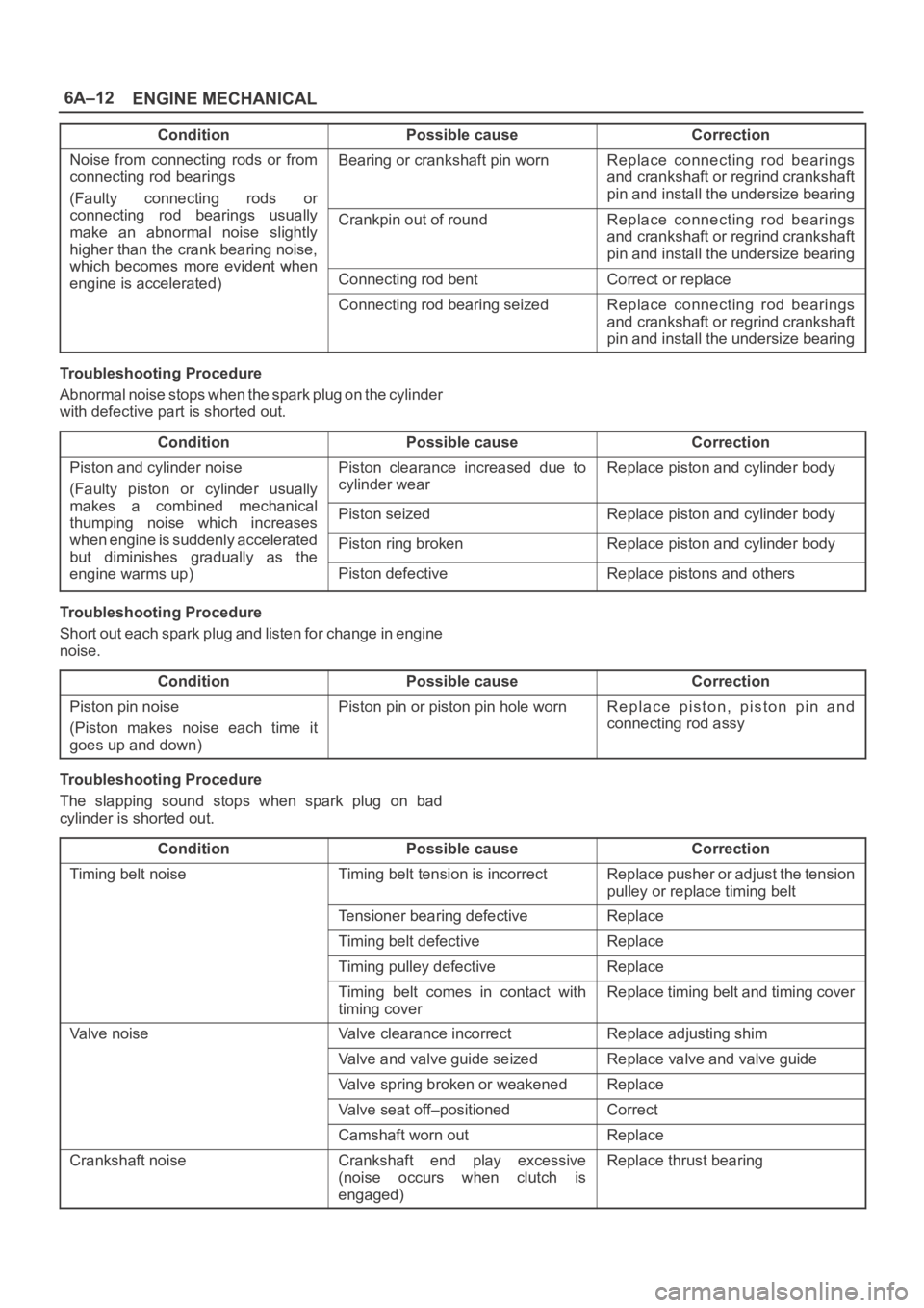
Noise from connecting rods or from
connecting rod bearings
(Faulty connecting rods orBearing or crankshaft pin wornReplace connecting rod bearings
and crankshaft or regrind crankshaft
pin and install the undersize bearing
yg
connecting rod bearings usually
make an abnormal noise slightly
higher than the crank bearing noise,
which becomes more evident when
Crankpin out of roundReplace connecting rod bearings
and crankshaft or regrind crankshaft
pin and install the undersize bearing
which becomes more evident when
engine is accelerated)Connecting rod bentCorrect or replaceg)
Connecting rod bearing seizedReplace connecting rod bearings
and crankshaft or regrind crankshaft
pin and install the undersize bearing
Troubleshooting Procedure
Abnormal noise stops when the spark plug on the cylinder
with defective part is shorted out.
Condition
Possible causeCorrection
Piston and cylinder noise
(Faulty piston or cylinder usually
kbidhil
Piston clearance increased due to
cylinder wearReplace piston and cylinder body
makes a combined mechanical
thumping noise which increasesPiston seizedReplace piston and cylinder bodyg
when engine is suddenly accelerated
but diminishes
gradually as thePiston ring brokenReplace piston and cylinder bodybut diminishes gradually as the
engine warms up)Piston defectiveReplace pistons and others
Troubleshooting Procedure
Short out each spark plug and listen for change in engine
noise.
Condition
Possible causeCorrection
Piston pin noise
(Piston makes noise each time it
goes up and down)Piston pin or piston pin hole wornReplace piston, piston pin and
connecting rod assy
Troubleshooting Procedure
The slapping sound stops when spark plug on bad
cylinder is shorted out.
Condition
Possible causeCorrection
Timing belt noiseTiming belt tension is incorrectReplace pusher or adjust the tension
pulley or replace timing belt
Tensioner bearing defectiveReplace
Timing belt defectiveReplace
Timing pulley defectiveReplace
Timing belt comes in contact with
timing coverReplace timing belt and timing cover
Valve noiseValve clearance incorrectReplace adjusting shim
Valve and valve guide seizedReplace valve and valve guide
Valve spring broken or weakenedReplace
Valve seat off–positionedCorrect
Camshaft worn outReplace
Crankshaft noiseCrankshaft end play excessive
(noise occurs when clutch is
engaged)Replace thrust bearing
Page 985 of 6000

6A–29
ENGINE MECHANICAL
Timing Belt
Removal
1. Disconnect battery ground cable.
2. Remove air cleaner assembly.
3. Remove radiator upper fan shroud from radiator.
4. Move drive belt tensioner to loose side using wrench
then remove drive belt.
850RW001
Legend
(1) Crankshaft Pulley
(2) Cooling Fan Pulley
(3) Tensioner
(4) Generator
(5) Air Conditioner Compressor
(6) Power Steering Oil Pump
(7) Drive Belt
5. Remove cooling fan assembly four nuts, then the
cooling fan assembly.
6. Remove cooling fan drive pulley assembly.
7. Remove idle pulley assembly.
8. Remove serpentine belt tensioner assembly.
9. Remove power steering pump assembly.
10. Remove crankshaft pulley assembly using
5–8840–0133–0 crankshaft holder, hold crankshaft
pulley remove center bolt, then the pulley.
11. Remove right side timing belt cover then left side
timing belt cover.
12. Remove lower timing belt cover
13. Remove pusher.CAUTION: The pusher prevents air from entering
the oil chamber. Its rod must always be facing
upward.
014RW011
Legend
(1) Up Side
(2) Down Side
(3) Direction For Installation
(4) Locking Pin
14. Remove timing belt.
CAUTION:
1. Do not bend or twist the belt, otherwise its core
could be damaged. The belt should not be bent at
a radius less than 30 mm.
2. Do not allow oil or other chemical substances to
come in contact with the belt. They will shorten
the life.
3. Do not attempt to pry or stretch the belt with a
screw driver or any other tool during installation.
4. Store timing belt in a cool and dark place. Never
expose the belt direct sunlight or heat.
Page 1075 of 6000
6C–8
ENGINE FUEL
7. Disconnect two fuel tank wiring connectors(4) on
front right side of tank.
8. Disconnect evapo fuel hose(5).
9. Disconnect fuel feed tube and fuel return tube(6).
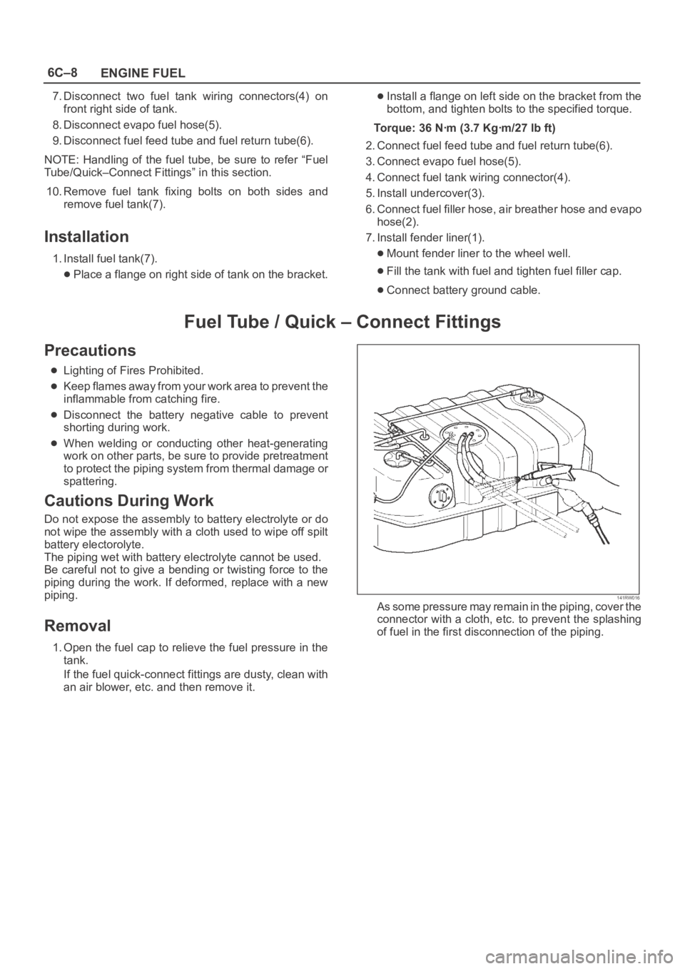
NOTE: Handling of the fuel tube, be sure to refer “Fuel
Tube/Quick–Connect Fittings” in this section.
10. Remove fuel tank fixing bolts on both sides and
remove fuel tank(7).
Installation
1. Install fuel tank(7).
Place a flange on right side of tank on the bracket.
Install a flange on left side on the bracket from the
bottom, and tighten bolts to the specified torque.
Torque: 36 Nꞏm (3.7 Kgꞏm/27 lb ft)
2. Connect fuel feed tube and fuel return tube(6).
3. Connect evapo fuel hose(5).
4. Connect fuel tank wiring connector(4).
5. Install undercover(3).
6. Connect fuel filler hose, air breather hose and evapo
hose(2).
7. Install fender liner(1).
Mount fender liner to the wheel well.
Fill the tank with fuel and tighten fuel filler cap.
Connect battery ground cable.
Fuel Tube / Quick – Connect Fittings
Precautions
Lighting of Fires Prohibited.
Keep flames away from your work area to prevent the
inflammable from catching fire.
Disconnect the battery negative cable to prevent
shorting during work.
When welding or conducting other heat-generating
work on other parts, be sure to provide pretreatment
to protect the piping system from thermal damage or
spattering.
Cautions During Work
Do not expose the assembly to battery electrolyte or do
not wipe the assembly with a cloth used to wipe off spilt
battery electorolyte.
The piping wet with battery electrolyte cannot be used.
Be careful not to give a bending or twisting force to the
piping during the work. If deformed, replace with a new
piping.
Removal
1. Open the fuel cap to relieve the fuel pressure in the
tank.
If the fuel quick-connect fittings are dusty, clean with
an air blower, etc. and then remove it.
141RW016As some pressure may remain in the piping, cover the
connector with a cloth, etc. to prevent the splashing
of fuel in the first disconnection of the piping.
Page 1076 of 6000
6C–9
ENGINE FUEL
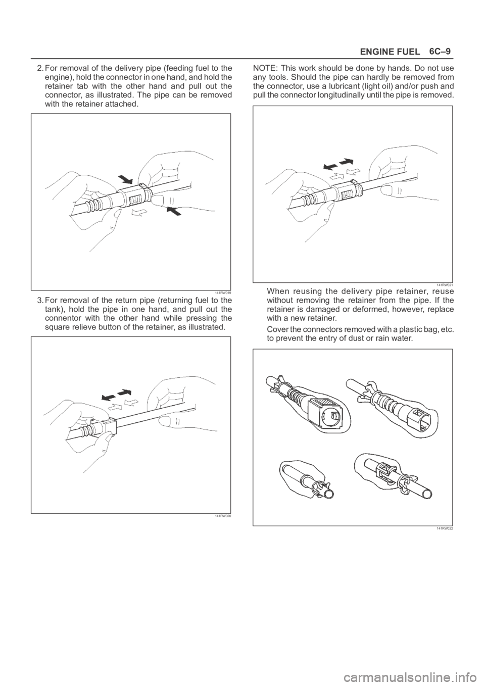
2. For removal of the delivery pipe (feeding fuel to the
engine), hold the connector in one hand, and hold the
retainer tab with the other hand and pull out the
connector, as illustrated. The pipe can be removed
with the retainer attached.
141RW019
3. For removal of the return pipe (returning fuel to the
tank), hold the pipe in one hand, and pull out the
connentor with the other hand while pressing the
square relieve button of the retainer, as illustrated.
141RW020
NOTE: This work should be done by hands. Do not use
any tools. Should the pipe can hardly be removed from
the connector, use a lubricant (light oil) and/or push and
pull the connector longitudinally until the pipe is removed.
141RW021When reusing the delivery pipe retainer, reuse
without removing the retainer from the pipe. If the
retainer is damaged or deformed, however, replace
with a new retainer.
Cover the connectors removed with a plastic bag, etc.
to prevent the entry of dust or rain water.
141RW022
Page 1077 of 6000
6C–10
ENGINE FUEL
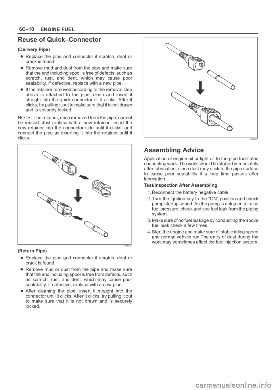
Reuse of Quick–Connector
(Delivery Pipe)
Replace the pipe and connector if scratch, dent or
crack is found.
Remove mud and dust from the pipe and make sure
that the end including spool is free of defects, such as
scratch, rust, and dent, which may cause poor
sealability. If defective, replace with a new pipe.
If the retainer removed according to the removal step
above is attached to the pipe, clean and insert it
straight into the quick-connector till it clicks. After it
clicks, try pulling it out to make sure that it is not drawn
and is securely locked.
NOTE: The retainer, once removed from the pipe, cannot
be reused. Just replace with a new retainer. Insert the
new retainer into the connector side until it clicks, and
connect the pipe as inserting it into the retainer until it
clicks.
141RW018
(Return Pipe)
Replace the pipe and connector if scratch, dent or
crack is found.
Remove mud or dust from the pipe and make sure
that the end including spool is free from defects, such
as scratch, rust, and dent, which may cause poor
sealability. If defective, replace with a new pipe.
After cleaning the pipe, insert it straight into the
connector until it clicks. After it clicks, try pulling it out
to make sure that it is not drawn and is securely
locked.
141RW017
Assembling Advice
Application of engine oil or light oil to the pipe facilitates
connecting work. The work should be started immediately
after lubrication, since dust may stick to the pipe surface
to cause poor sealability if a long time passes after
lubrication.
Test/Inspection After Assembling
1. Reconnect the battery negative cable.
2. Turn the ignition key to the “ON” position and check
pump startup sound. As the pump is actuated to raise
fuel pressure, check and see fuel leak from the piping
system.
3. Make sure of no fuel leakage by conducting the above
fuel leak check a few times.
4. Start the engine and make sure of stable idling speed
and normal vehicle run.The entry of dust during the
work may sometimes affect the fuel injection system.
Page 1081 of 6000
6D1–2
ENGINE ELECTRICAL
Battery
General Description
There are six battery fluid caps on top of the battery.
These are covered by a paper label.
The battery is completely sealed except for the six small
vent holes on the side. These vent holes permit the
escape of small amounts of gas generated by the battery.
This type of battery has the following advantages over
conventional batteries:
1. There is no need to add water during the entire
service life of the battery.
2. The battery protects itself against overcharging.
The battery will refuse to accept an extensive charge.
(A conventional battery will accept an excessive
charge, resulting in gassing and loss of battery fluid.)
3. The battery is much less vulnerable to self discharge
than a conventional type battery.
Diagnosis
1. Visual Inspection
Inspect the battery for obvious physical damage, such as
a cracked or broken case, which would permit electrolyte
loss.
Replace the battery if obvious physical damage is
discovered during inspection.
Check for any other physical damage and correct it as
necessary.
2. Hydrometer Check
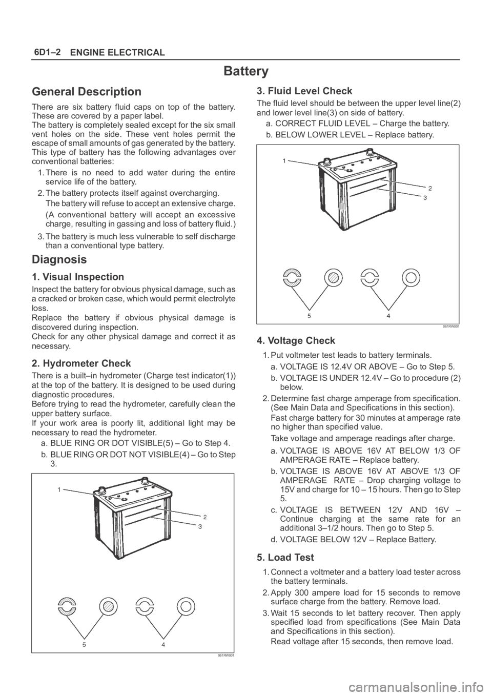
There is a built–in hydrometer (Charge test indicator(1))
at the top of the battery. It is designed to be used during
diagnostic procedures.
Before trying to read the hydrometer, carefully clean the
upper battery surface.
If your work area is poorly lit, additional light may be
necessary to read the hydrometer.
a. BLUE RING OR DOT VISIBLE(5) – Go to Step 4.
b . B L U E R I N G O R D O T N O T V I S I B L E ( 4 ) – G o t o S t e p
3.
061RW001
3. Fluid Level Check
The fluid level should be between the upper level line(2)
and lower level line(3) on side of battery.
a. CORRECT FLUID LEVEL – Charge the battery.
b. BELOW LOWER LEVEL – Replace battery.
061RW001
4. Voltage Check
1. Put voltmeter test leads to battery terminals.
a. VOLTAGE IS 12.4V OR ABOVE – Go to Step 5.
b. VOLTAGE IS UNDER 12.4V – Go to procedure (2)
below.
2. Determine fast charge amperage from specification.
(See Main Data and Specifications in this section).
Fast charge battery for 30 minutes at amperage rate
no higher than specified value.
Take voltage and amperage readings after charge.
a. VOLTAGE IS ABOVE 16V AT BELOW 1/3 OF
AMPERAGE RATE – Replace battery.
b. VOLTAGE IS ABOVE 16V AT ABOVE 1/3 OF
AMPERAGE RATE – Drop charging voltage to
15V and charge for 10 – 15 hours. Then go to Step
5.
c. VOLTAGE IS BETWEEN 12V AND 16V –
Continue charging at the same rate for an
additional 3–1/2 hours. Then go to Step 5.
d. VOLTAGE BELOW 12V – Replace Battery.
5. Load Test
1. Connect a voltmeter and a battery load tester across
the battery terminals.
2. Apply 300 ampere load for 15 seconds to remove
surface charge from the battery. Remove load.
3. Wait 15 seconds to let battery recover. Then apply
specified load from specifications (See Main Data
and Specifications in this section).
Read voltage after 15 seconds, then remove load.
Page 1082 of 6000
ENGINE ELECTRICAL6D1–3
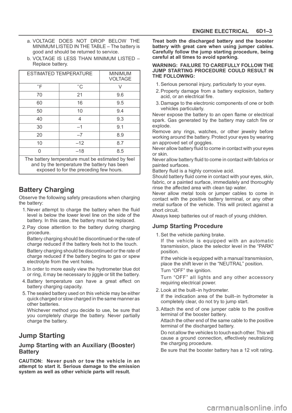
a. VOLTAGE DOES NOT DROP BELOW THE
MINIMUM LISTED IN THE TABLE – The battery is
good and should be returned to service.
b. VOLTAGE IS LESS THAN MINIMUM LISTED –
Replace battery.
ESTIMATED TEMPERATURE
MINIMUM
VOLTAGE
FCV
70219.6
60169.5
50109.4
4049.3
30–19.1
20–78.9
10–128.7
0–188.5
The battery temperature must be estimated by feel
and by the temperature the battery has been
exposed to for the preceding few hours.
Battery Charging
Observe the following safety precautions when charging
the battery:
1. Never attempt to charge the battery when the fluid
level is below the lower level line on the side of the
battery. In this case, the battery must be replaced.
2. Pay close attention to the battery during charging
procedure.
Battery charging should be discontinued or the rate of
charge reduced if the battery feels hot to the touch.
Battery charging should be discontinued or the rate of
charge reduced if the battery begins to gas or spew
electrolyte from the vent holes.
3. In order to more easily view the hydrometer blue dot
or ring, it may be necessary to jiggle or tilt the battery.
4. Battery temperature can have a great effect on
battery charging capacity.
5. The sealed battery used on this vehicle may be either
quick charged or slow charged in the same manner as
other batteries.
Whichever method you decide to use, be sure that
you completely charge the battery. Never partially
charge the battery.
Jump Starting
Jump Starting with an Auxiliary (Booster)
Battery
CAUTION: Never push or tow the vehicle in an
attempt to start it. Serious damage to the emission
system as well as other vehicle parts will result.Treat both the discharged battery and the booster
battery with great care when using jumper cables.
Carefully follow the jump starting procedure, being
careful at all times to avoid sparking.
WARNING: FAILURE TO CAREFULLY FOLLOW THE
JUMP STARTING PROCEDURE COULD RESULT IN
THE FOLLOWING:
1. Serious personal injury, particularly to your eyes.
2. Property damage from a battery explosion, battery
acid, or an electrical fire.
3. Damage to the electronic components of one or both
vehicles particularly.
Never expose the battery to an open flame or electrical
spark. Gas generated by the battery may catch fire or
explode.
Remove any rings, watches, or other jewelry before
working around the battery. Protect your eyes by wearing
an approved set of goggles.
Never allow battery fluid to come in contact with your eyes
or skin.
Never allow battery fluid to come in contact with fabrics or
painted surfaces.
Battery fluid is a highly corrosive acid.
Should battery fluid come in contact with your eyes, skin,
fabric, or a painted surface, immediately and thoroughly
rinse the affected area with clean tap water.
Never allow metal tools or jumper cables to come in
contact with the positive battery terminal, or any other
metal surface of the vehicle. This will protect against a
short circuit.
Always keep batteries out of reach of young children.
Jump Starting Procedure
1. Set the vehicle parking brake.
If the vehicle is equipped with an automatic
transmission, place the selector level in the “PARK”
position.
If the vehicle is equipped with a manual transmission,
place the shift lever in the “NEUTRAL” position.
Turn “OFF” the ignition.
Turn “OFF” all lights and any other accessory
requiring electrical power.
2. Look at the built–in hydrometer.
If the indication area of the built–in hydrometer is
completely clear, do not try to jump start.
3. Attach the end of one jumper cable to the positive
terminal of the booster battery.
Attach the other end of the same cable to the positive
terminal of the discharged battery.
Do not allow the vehicles to touch each other. This will
cause a ground connection, effectively neutralizing
the charging procedure.
Be sure that the booster battery has a 12 volt rating.