1998 OPEL FRONTERA catalytic converter
[x] Cancel search: catalytic converterPage 1393 of 6000
6E–276
ENGINE DRIVEABILITY AND EMISSIONS
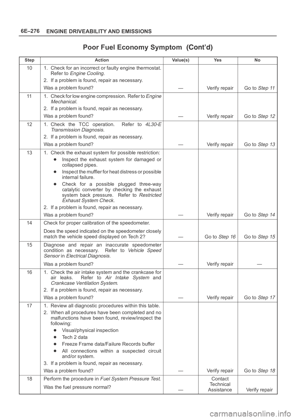
Poor Fuel Economy Symptom
StepNo Ye s Va l u e ( s ) Action
101. Check for an incorrect or faulty engine thermostat.
Refer to
Engine Cooling.
2. If a problem is found, repair as necessary.
Was a problem found?
—Verify repairGo to Step 11
111. Check for low engine compression. Refer to Engine
Mechanical
.
2. If a problem is found, repair as necessary.
Was a problem found?
—Verify repairGo to Step 12
121. Check the TCC operation. Refer to 4L30-E
Transmission Diagnosis
.
2. If a problem is found, repair as necessary.
Was a problem found?
—Verify repairGo to Step 13
131. Check the exhaust system for possible restriction:
Inspect the exhaust system for damaged or
collapsed pipes.
Inspect the muffler for heat distress or possible
internal failure.
Check for a possible plugged three-way
catalytic converter by checking the exhaust
system back pressure. Refer to
Restricted
Exhaust System Check
.
2. If a problem is found, repair as necessary.
Was a problem found?
—Verify repairGo to Step 14
14Check for proper calibration of the speedometer.
Does the speed indicated on the speedometer closely
match the vehicle speed displayed on Tech 2?
—Go to Step 16Go to Step 15
15Diagnose and repair an inaccurate speedometer
condition as necessary. Refer to
Vehicle Speed
Sensor
in Electrical Diagnosis.
Was a problem found?
—Verify repair—
161. Check the air intake system and the crankcase for
air leaks. Refer to
Air Intake System and
Crankcase Ventilation System.
2. If a problem is found, repair as necessary.
Was a problem found?
—Verify repairGo to Step 17
171. Review all diagnostic procedures within this table.
2. When all procedures have been completed and no
malfunctions have been found, review/inspect the
following:
Visual/physical inspection
Te c h 2 d a t a
Freeze Frame data/Failure Records buffer
All connections within a suspected circuit
and/or system.
3. If a problem is found, repair as necessary.
Was a problem found?
—Verify repairGo to Step 18
18Perform the procedure in Fuel System Pressure Test.
Was the fuel pressure normal?
—
Contact
Te c h n i c a l
Assistance
Verify repair
Page 1411 of 6000
6E–294
ENGINE DRIVEABILITY AND EMISSIONS
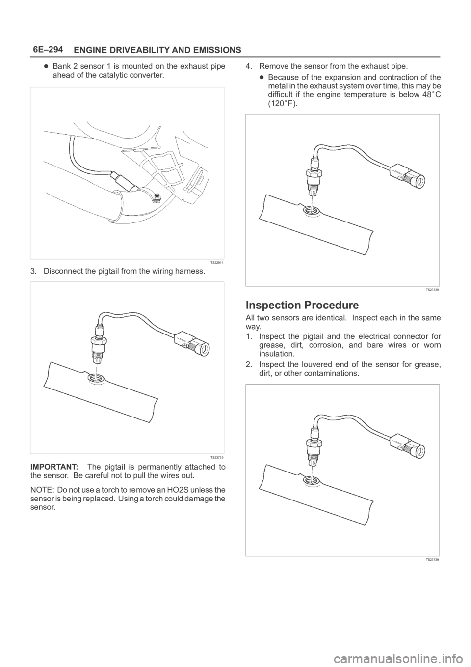
Bank 2 sensor 1 is mounted on the exhaust pipe
ahead of the catalytic converter.
TS22914
3. Disconnect the pigtail from the wiring harness.
TS23739
IMPORTANT:The pigtail is permanently attached to
the sensor. Be careful not to pull the wires out.
NOTE: Do not use a torch to remove an HO2S unless the
sensor is being replaced. Using a torch could damage the
sensor.4. Remove the sensor from the exhaust pipe.
Because of the expansion and contraction of the
metal in the exhaust system over time, this may be
difficult if the engine temperature is below 48
C
(120
F).
TS23739
Inspection Procedure
All two sensors are identical. Inspect each in the same
way.
1. Inspect the pigtail and the electrical connector for
grease, dirt, corrosion, and bare wires or worn
insulation.
2. Inspect the louvered end of the sensor for grease,
dirt, or other contaminations.
TS23739
Page 1442 of 6000
6E–325 ENGINE DRIVEABILITY AND EMISSIONS
Spark Plug Gap Check
Check the gap of all spark plugs before installation.
Use a round wire feeler gauge to ensure an accurate
check.
Plugs installed with the wrong gap can cause poor
engine performance and excessive emissions.
Installation Procedure
NOTE: The plug must thread smoothly into the cylinder
head and be fully seated. Use a thread chaser if
necessary to clean the threads in the cylinder head.
Cross-threading or failure to fully seat the spark plug can
cause plug overheating, exhaust blow-by gas, or thread
damage. Do not overtighten the spark plugs. Over
tightening can cause aluminum threads to strip.
1. Install the spark plug in the engine. Use the
appropriate spark plug socket.
Tighten
Tighten the spark plug to 18 Nꞏm (13 lb ft.).
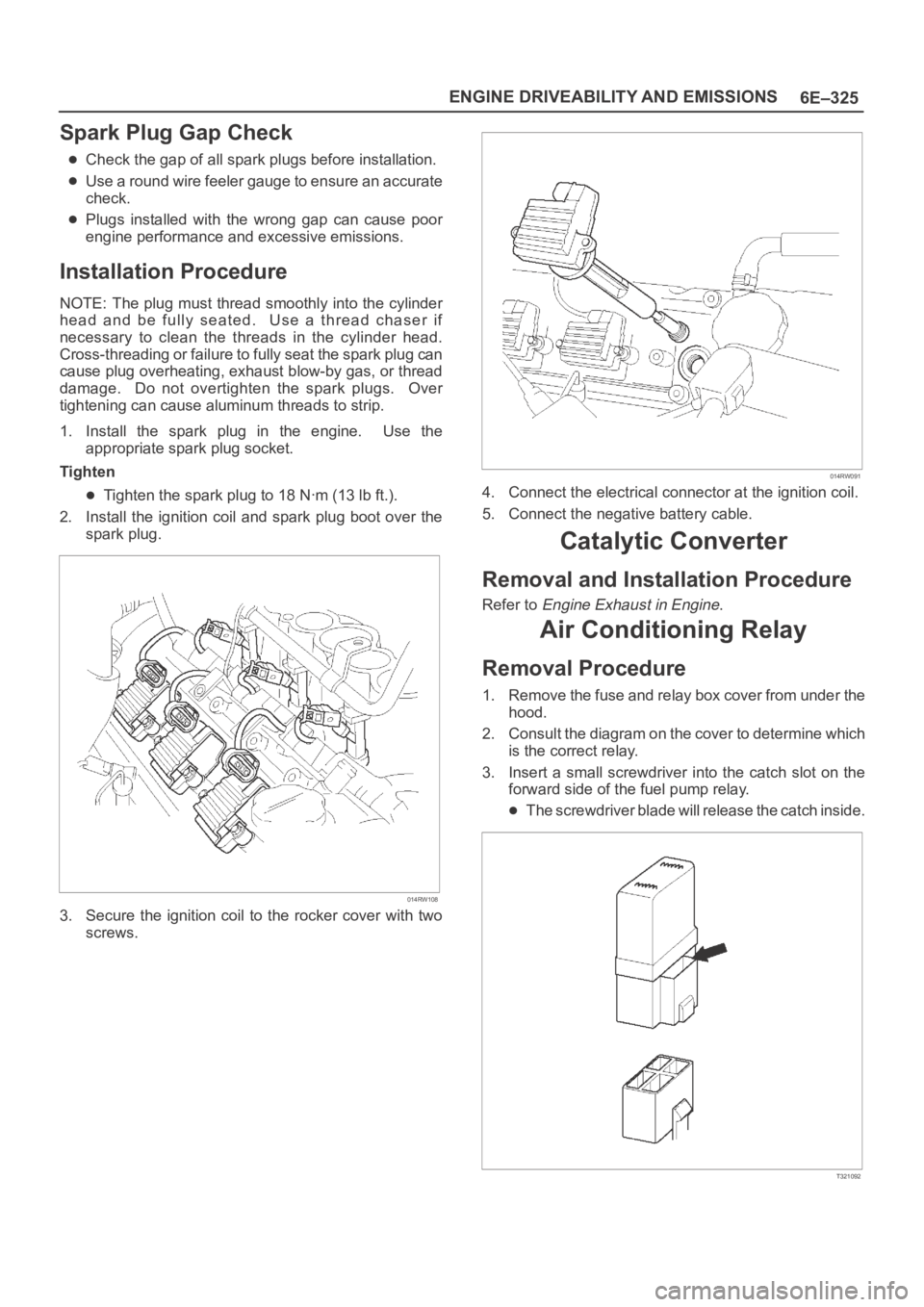
2. Install the ignition coil and spark plug boot over the
spark plug.
014RW108
3. Secure the ignition coil to the rocker cover with two
screws.
014RW091
4. Connect the electrical connector at the ignition coil.
5. Connect the negative battery cable.
Catalytic Converter
Removal and Installation Procedure
Refer to Engine Exhaust in Engine.
Air Conditioning Relay
Removal Procedure
1. Remove the fuse and relay box cover from under the
hood.
2. Consult the diagram on the cover to determine which
is the correct relay.
3. Insert a small screwdriver into the catch slot on the
forward side of the fuel pump relay.
The screwdriver blade will release the catch inside.
T321092
Page 1459 of 6000
6E–342
ENGINE DRIVEABILITY AND EMISSIONS
PCM to calculate true sequential multiport fuel injection
(SFI). Loss of this signal will set a DTC P0341. If the CMP
signal is lost while the engine is running, the fuel injection
system will shift to a calculated sequential fuel injection
based on the last fuel injection pulse, and the engine will
continue to run. The engine can be restarted and will run
in the calculated sequential mode as long as the fault is
present, with a 1-in-6 chance of being correct.
Clear Flood Mode
Clear a flooded engine by pushing the accelerator pedal
down all the way. The PCM then de-energizes the fuel
injectors. The PCM holds the fuel injectors de-energized
as long as the throttle remains above 80% and the engine
speed is below 800 RPM. If the throttle position becomes
less than 80%, the PCM again begins to pulse the
injectors “ON” and “OFF,” allowing fuel into the cylinders.
Deceleration Mode
The PCM reduces the amount of fuel injected when it
detects a decrease in the throttle position and the air flow.
When deceleration is very fast, the PCM may cut off fuel
completely for short periods.
Engine Speed/Vehicle Speed/Fuel Disable
Mode
The PCM monitors engine speed. It turns off the fuel
injectors when the engine speed increase above 6400
RPM. The fuel injectors are turned back on when engine
speed decreases below 6150 RPM.
Fuel Cutoff Mode
No fuel is delivered by the fuel injectors when the ignition
is “OFF.” This prevents engine run-on. In addition, the
PCM suspends fuel delivery if no reference pulses are
detected (engine not running) to prevent engine flooding.
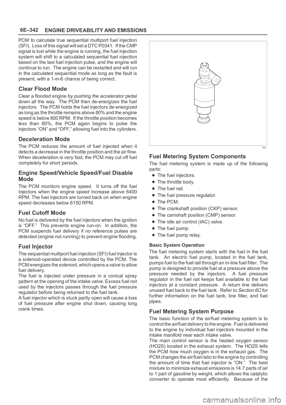
Fuel Injector
The sequential multiport fuel injection (SFI) fuel injector is
a solenoid-operated device controlled by the PCM. The
PCM energizes the solenoid, which opens a valve to allow
fuel delivery.
The fuel is injected under pressure in a conical spray
pattern at the opening of the intake valve. Excess fuel not
used by the injectors passes through the fuel pressure
regulator before being returned to the fuel tank.
A fuel injector which is stuck partly open will cause a loss
of fuel pressure after engine shut down, causing long
crank times.
0003
Fuel Metering System Components
The fuel metering system is made up of the following
parts:
The fuel injectors.
The throttle body.
The fuel rail.
The fuel pressure regulator.
The PCM.
The crankshaft position (CKP) sensor.
The camshaft position (CMP) sensor.
The idle air control (IAC) valve.
The fuel pump.
The fuel pump relay.
Basic System Operation
The fuel metering system starts with the fuel in the fuel
tank. An electric fuel pump, located in the fuel tank,
pumps fuel to the fuel rail through an in-line fuel filter. The
pump is designed to provide fuel at a pressure above the
pressure needed by the injectors. A fuel pressure
regulator in the fuel rail keeps fuel available to the fuel
injectors at a constant pressure. A return line delivers
unused fuel back to the fuel tank. Refer to
Section 6C f o r
further information on the fuel tank, line filter, and fuel
pipes.
Fuel Metering System Purpose
The basic function of the air/fuel metering system is to
control the air/fuel delivery to the engine. Fuel is delivered
to the engine by individual fuel injectors mounted in the
intake manifold near each intake valve.
The main control sensor is the heated oxygen sensor
(HO2S) located in the exhaust system. The HO2S tells
the PCM how much oxygen is in the exhaust gas. The
PCM changes the air/fuel ratio to the engine by controlling
the amount of time that fuel injector is “ON.” The best
mixture to minimize exhaust emissions is 14.7 parts of air
to 1 part of gasoline by weight, which allows the catalytic
converter to operate most efficiently. Because of the
Page 1472 of 6000
6F–1 ENGINE EXHAUST
ENGINE
ENGINE EXHAUST
CONTENTS
Service Precaution 6F–1. . . . . . . . . . . . . . . . . . . . . .
General Description 6F–2. . . . . . . . . . . . . . . . . . . . .
Front Exhaust Pipe 6F–4. . . . . . . . . . . . . . . . . . . . . .
Front Exhaust Pipe and Associated Parts 6F–4.
Removal 6F–4. . . . . . . . . . . . . . . . . . . . . . . . . . . . .
Installation 6F–4. . . . . . . . . . . . . . . . . . . . . . . . . . . .
Three Way Catalytic Converter 6F–5. . . . . . . . . . . .
Removal 6F–5. . . . . . . . . . . . . . . . . . . . . . . . . . . . .
Installation 6F–5. . . . . . . . . . . . . . . . . . . . . . . . . . . . Exhaust Silencer 6F–6. . . . . . . . . . . . . . . . . . . . . . . .
Exhaust Silencer and Associated Parts 6F–6. . .
Removal 6F–6. . . . . . . . . . . . . . . . . . . . . . . . . . . . .
Installation 6F–6. . . . . . . . . . . . . . . . . . . . . . . . . . . .
Rear Exhaust pipe 6F–7. . . . . . . . . . . . . . . . . . . . . . .
Rear Exhaust pipe and Associated Parts 6F–7.
Removal 6F–7. . . . . . . . . . . . . . . . . . . . . . . . . . . . .
Installation 6F–7. . . . . . . . . . . . . . . . . . . . . . . . . . . .
Main Data and Specifications 6F–8. . . . . . . . . . . . .
Service Precaution
WARNING: IF SO EQUIPPED WITH A
SUPPLEMENTAL RESTRAINT SYSTEM (SRS),
REFER TO THE SRS COMPONENT AND WIRING
LOCATION VIEW IN ORDER TO DETERMINE
WHETHER YOU ARE PERFORMING SERVICE ON OR
NEAR THE SRS COMPONENTS OR THE SRS
WIRING. WHEN YOU ARE PERFORMING SERVICE
ON OR NEAR THE SRS COMPONENTS OR THE SRS
WIRING, REFER TO THE SRS SERVICE
INFORMATION. FAILURE TO FOLLOW WARNINGS
COULD RESULT IN POSSIBLE AIR BAG
DEPLOYMENT, PERSONAL INJURY, OR
OTHERWISE UNNEEDED SRS SYSTEM REPAIRS.
CAUTION: Always use the correct fastener in the
proper location. When you replace a fastener, use
ONLY the exact part number for that application.
ISUZU will call out those fasteners that require a
replacement after removal. ISUZU will also call out
the fasteners that require thread lockers or thread
sealant. UNLESS OTHERWISE SPECIFIED, do not
use supplemental coatings (Paints, greases, or other
corrosion inhibitors) on threaded fasteners or
fastener joint interfaces. Generally, such coatings
adversely affect the fastener torque and the joint
clamping force, and may damage the fastener. When
you install fasteners, use the correct tightening
sequence and specifications. Following these
instructions can help you avoid damage to parts and
systems.
Page 1473 of 6000
6F–2ENGINE EXHAUST
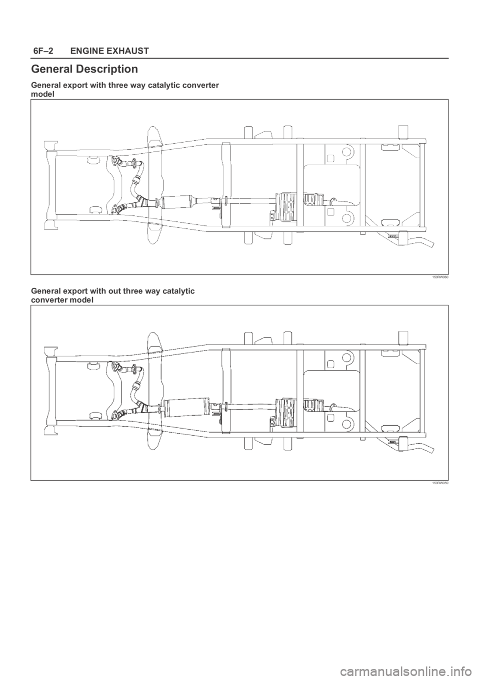
General Description
General export with three way catalytic converter
model
150RW060
General export with out three way catalytic
converter model
150RW059
Page 1474 of 6000
6F–3 ENGINE EXHAUST
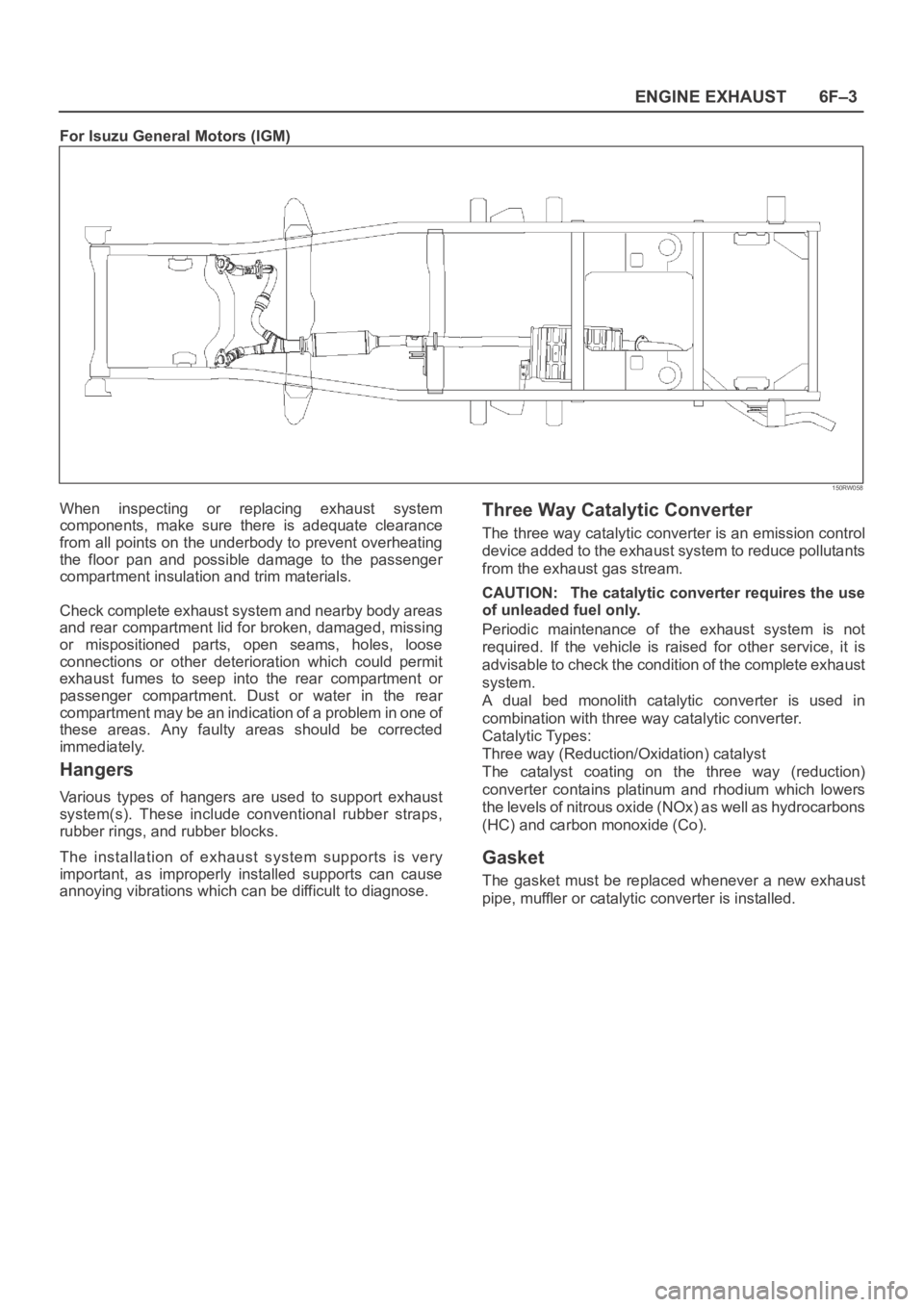
For Isuzu General Motors (IGM)
150RW058
When inspecting or replacing exhaust system
components, make sure there is adequate clearance
from all points on the underbody to prevent overheating
the floor pan and possible damage to the passenger
compartment insulation and trim materials.
Check complete exhaust system and nearby body areas
and rear compartment lid for broken, damaged, missing
or mispositioned parts, open seams, holes, loose
connections or other deterioration which could permit
exhaust fumes to seep into the rear compartment or
passenger compartment. Dust or water in the rear
compartment may be an indication of a problem in one of
these areas. Any faulty areas should be corrected
immediately.
Hangers
Various types of hangers are used to support exhaust
system(s). These include conventional rubber straps,
rubber rings, and rubber blocks.
The installation of exhaust system supports is very
important, as improperly installed supports can cause
annoying vibrations which can be difficult to diagnose.
Three Way Catalytic Converter
The three way catalytic converter is an emission control
device added to the exhaust system to reduce pollutants
from the exhaust gas stream.
CAUTION: The catalytic converter requires the use
of unleaded fuel only.
Periodic maintenance of the exhaust system is not
required. If the vehicle is raised for other service, it is
advisable to check the condition of the complete exhaust
system.
A dual bed monolith catalytic converter is used in
combination with three way catalytic converter.
Catalytic Types:
Three way (Reduction/Oxidation) catalyst
The catalyst coating on the three way (reduction)
converter contains platinum and rhodium which lowers
the levels of nitrous oxide (NOx) as well as hydrocarbons
(HC) and carbon monoxide (Co).
Gasket
The gasket must be replaced whenever a new exhaust
pipe, muffler or catalytic converter is installed.
Page 1476 of 6000
6F–5 ENGINE EXHAUST
Three Way Catalytic Converter
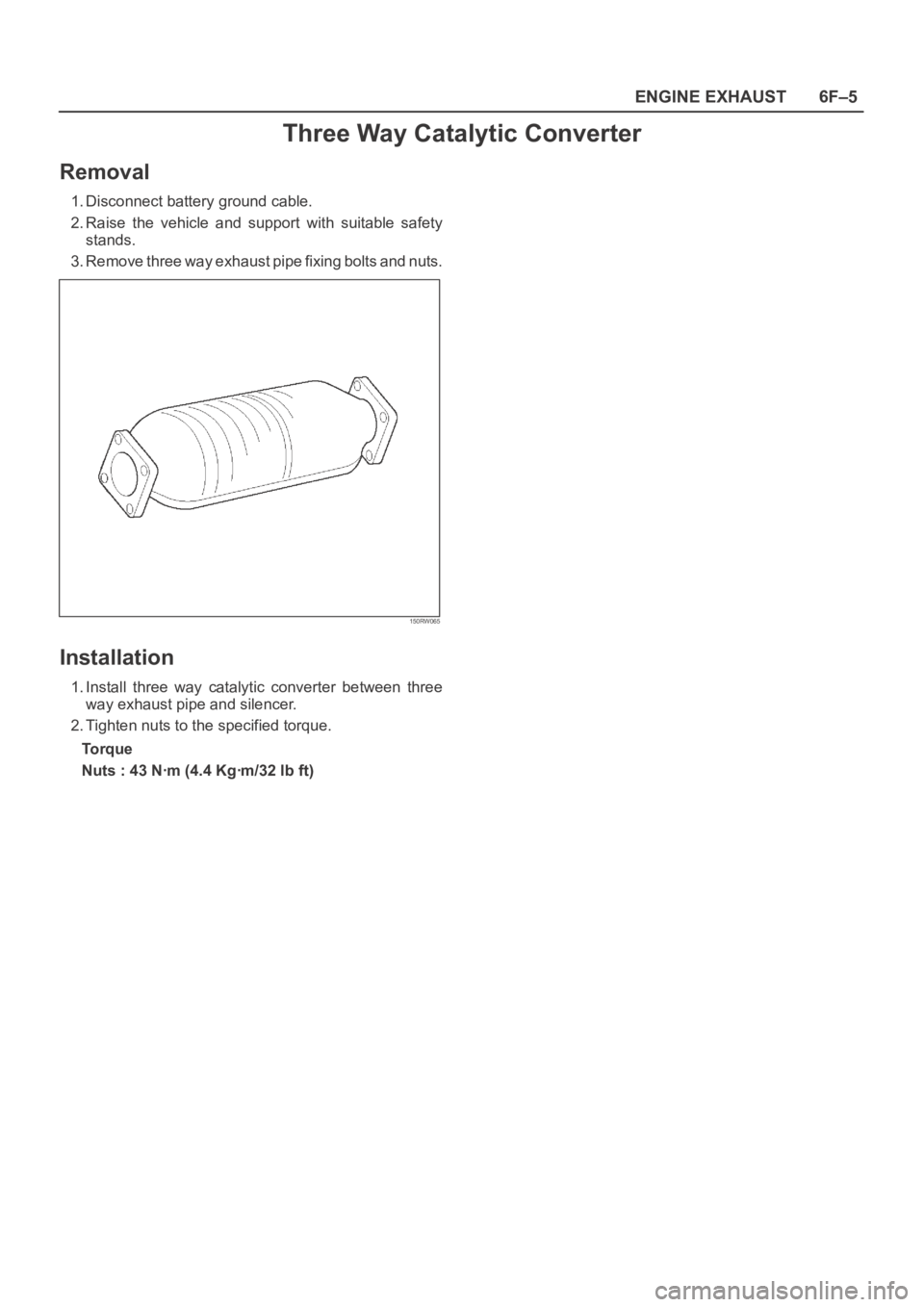
Removal
1. Disconnect battery ground cable.
2. Raise the vehicle and support with suitable safety
stands.
3. Remove three way exhaust pipe fixing bolts and nuts.
150RW065
Installation
1. Install three way catalytic converter between three
way exhaust pipe and silencer.
2. Tighten nuts to the specified torque.
Torque
Nuts : 43 Nꞏm (4.4 Kgꞏm/32 lb ft)