1998 OPEL FRONTERA catalytic converter
[x] Cancel search: catalytic converterPage 4730 of 6000
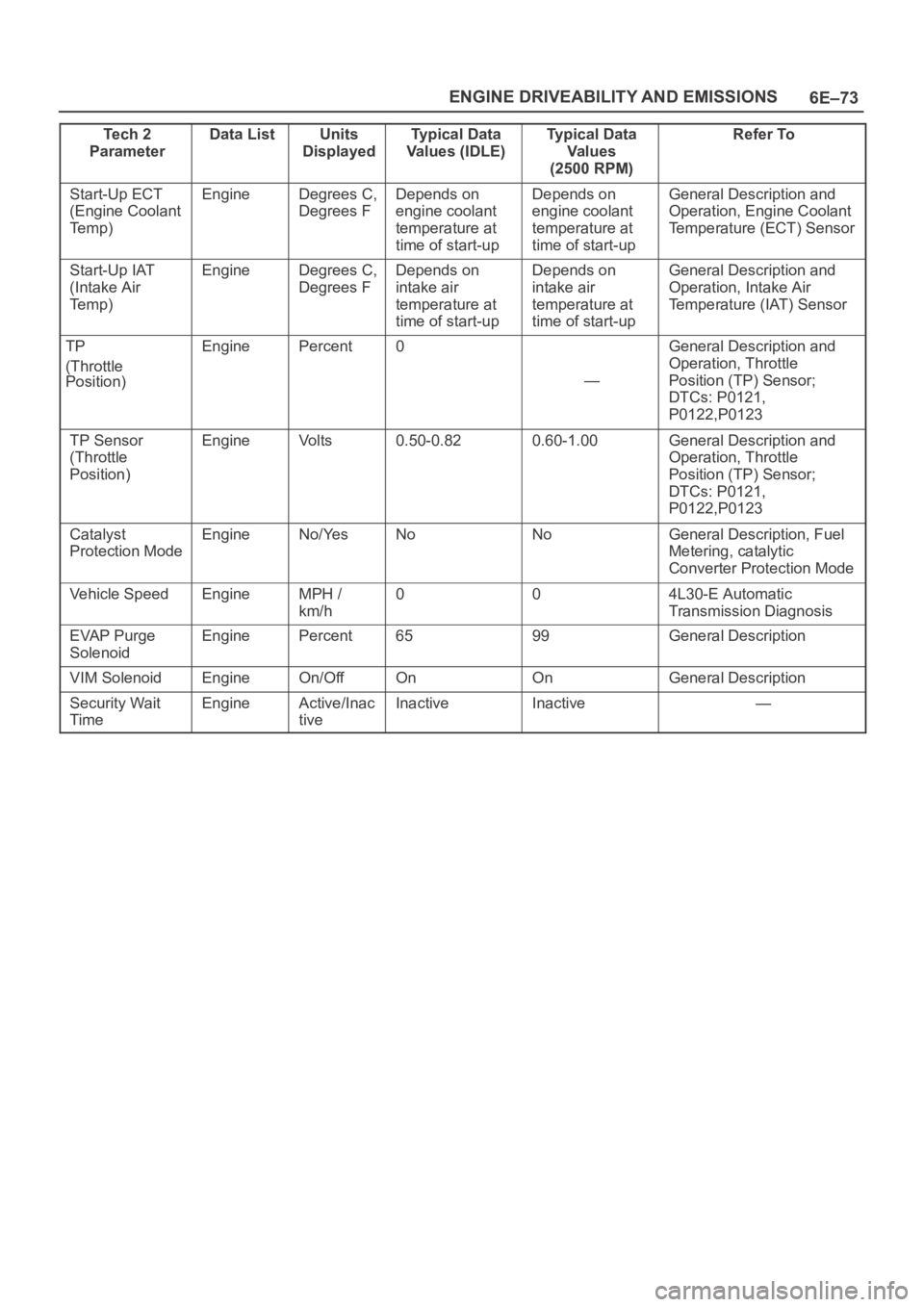
6E–73 ENGINE DRIVEABILITY AND EMISSIONS
Te c h 2
ParameterRefer To Typical Data
Va l u e s
(2500 RPM) Typical Data
Values (IDLE) Units
Displayed Data List
Start-Up ECT
(Engine Coolant
Te m p )EngineDegrees C,
Degrees FDepends on
engine coolant
temperature at
time of start-upDepends on
engine coolant
temperature at
time of start-upGeneral Description and
Operation, Engine Coolant
Temperature (ECT) Sensor
Start-Up IAT
(Intake Air
Te m p )EngineDegrees C,
Degrees FDepends on
intake air
temperature at
time of start-upDepends on
intake air
temperature at
time of start-upGeneral Description and
Operation, Intake Air
Temperature (IAT) Sensor
TP
(Throttle
Position)EnginePercent0
—
General Description and
Operation, Throttle
Position (TP) Sensor;
DTCs: P0121,
P0122,P0123
TP Sensor
(Throttle
Position)EngineVo l t s0.50-0.820.60-1.00General Description and
Operation, Throttle
Position (TP) Sensor;
DTCs: P0121,
P0122,P0123
Catalyst
Protection ModeEngineNo/YesNoNoGeneral Description, Fuel
Metering, catalytic
Converter Protection Mode
Vehicle SpeedEngineMPH /
km/h004L30-E Automatic
Transmission Diagnosis
EVAP Purge
SolenoidEnginePercent6599General Description
VIM SolenoidEngineOn/OffOnOnGeneral Description
Security Wait
TimeEngineActive/Inac
tiveInactiveInactive—
Page 4881 of 6000
6E–224
ENGINE DRIVEABILITY AND EMISSIONS
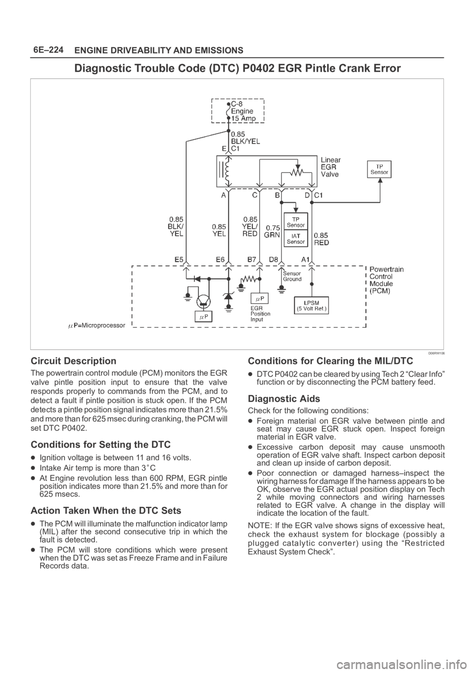
Diagnostic Trouble Code (DTC) P0402 EGR Pintle Crank Error
D06RW106
Circuit Description
The powertrain control module (PCM) monitors the EGR
valve pintle position input to ensure that the valve
responds properly to commands from the PCM, and to
detect a fault if pintle position is stuck open. If the PCM
detects a pintle position signal indicates more than 21.5%
and more than for 625 msec during cranking, the PCM will
set DTC P0402.
Conditions for Setting the DTC
Ignition voltage is between 11 and 16 volts.
Intake Air temp is more than 3C
At Engine revolution less than 600 RPM, EGR pintle
position indicates more than 21.5% and more than for
625 msecs.
Action Taken When the DTC Sets
The PCM will illuminate the malfunction indicator lamp
(MIL) after the second consecutive trip in which the
fault is detected.
The PCM will store conditions which were present
w h e n t h e D T C w a s s e t a s F r e e z e F r a m e a n d i n F a i l u r e
Records data.
Conditions for Clearing the MIL/DTC
DTC P0402 can be cleared by using Tech 2 “Clear Info”
function or by disconnecting the PCM battery feed.
Diagnostic Aids
Check for the following conditions:
Foreign material on EGR valve between pintle and
seat may cause EGR stuck open. Inspect foreign
material in EGR valve.
Excessive carbon deposit may cause unsmooth
operation of EGR valve shaft. Inspect carbon deposit
and clean up inside of carbon deposit.
Poor connection or damaged harness–inspect the
wiring harness for damage If the harness appears to be
OK, observe the EGR actual position display on Tech
2 while moving connectors and wiring harnesses
related to EGR valve. A change in the display will
indicate the location of the fault.
NOTE: If the EGR valve shows signs of excessive heat,
check the exhaust system for blockage (possibly a
plugged catalytic converter) using the “Restricted
Exhaust System Check”.
Page 4924 of 6000
6E–267 ENGINE DRIVEABILITY AND EMISSIONS
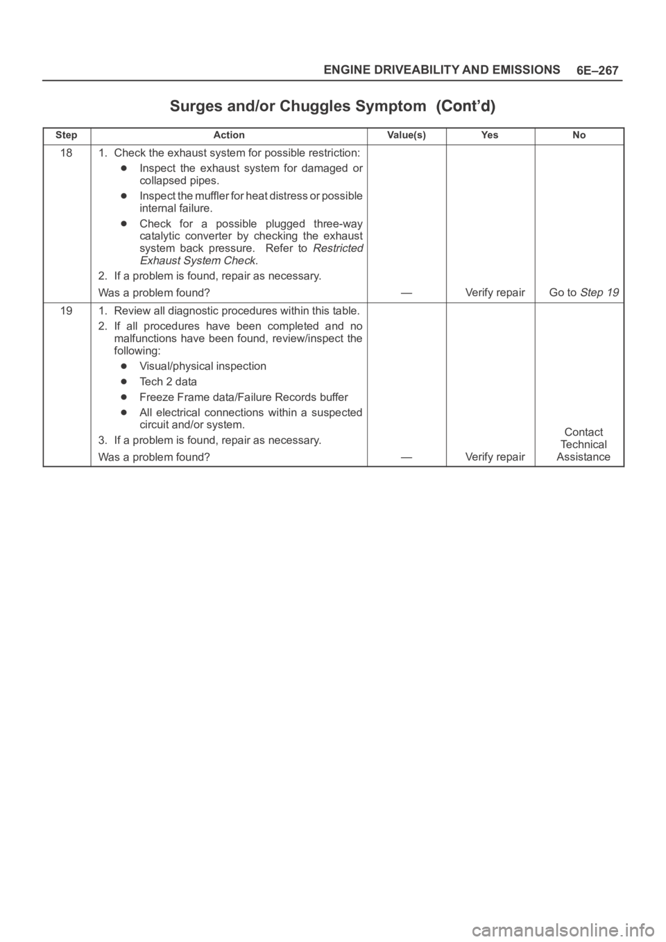
Surges and/or Chuggles Symptom
StepNo Ye s Va l u e ( s ) Action
181. Check the exhaust system for possible restriction:
Inspect the exhaust system for damaged or
collapsed pipes.
Inspect the muffler for heat distress or possible
internal failure.
Check for a possible plugged three-way
catalytic converter by checking the exhaust
system back pressure. Refer to
Restricted
Exhaust System Check
.
2. If a problem is found, repair as necessary.
Was a problem found?
—Verify repairGo to Step 19
191. Review all diagnostic procedures within this table.
2. If all procedures have been completed and no
malfunctions have been found, review/inspect the
following:
Visual/physical inspection
Te c h 2 d a t a
Freeze Frame data/Failure Records buffer
All electrical connections within a suspected
circuit and/or system.
3. If a problem is found, repair as necessary.
Was a problem found?
—Verify repair
Contact
Te c h n i c a l
Assistance
Page 4926 of 6000
6E–269 ENGINE DRIVEABILITY AND EMISSIONS
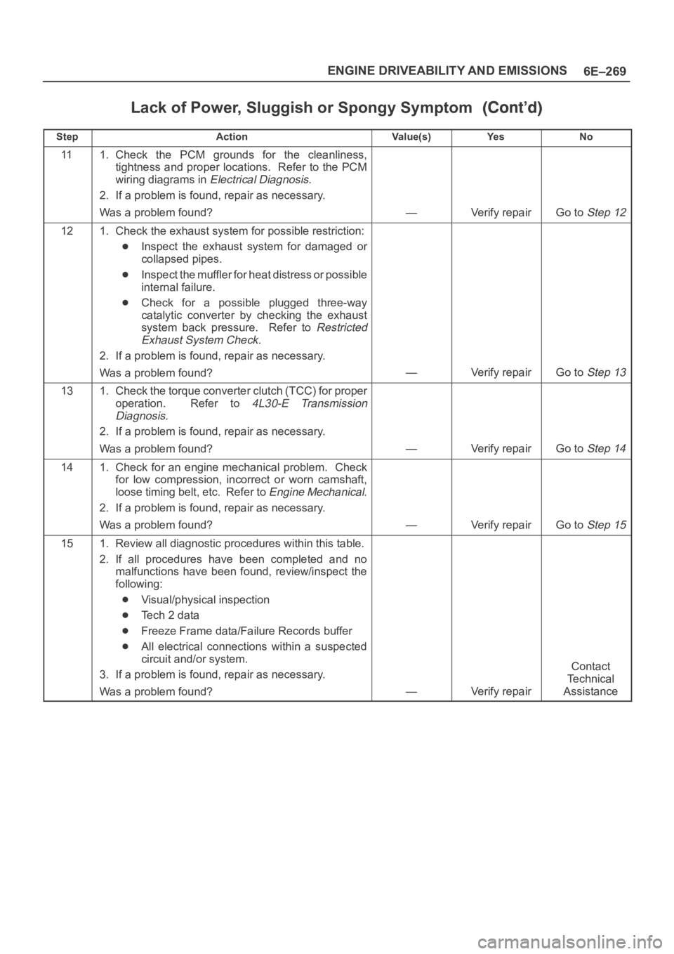
Lack of Power, Sluggish or Spongy Symptom
StepNo Ye s Va l u e ( s ) Action
111. Check the PCM grounds for the cleanliness,
tightness and proper locations. Refer to the PCM
wiring diagrams in
Electrical Diagnosis.
2. If a problem is found, repair as necessary.
Was a problem found?
—Verify repairGo to Step 12
121. Check the exhaust system for possible restriction:
Inspect the exhaust system for damaged or
collapsed pipes.
Inspect the muffler for heat distress or possible
internal failure.
Check for a possible plugged three-way
catalytic converter by checking the exhaust
system back pressure. Refer to
Restricted
Exhaust System Check
.
2. If a problem is found, repair as necessary.
Was a problem found?
—Verify repairGo to Step 13
131. Check the torque converter clutch (TCC) for proper
operation. Refer to
4L30-E Transmission
Diagnosis
.
2. If a problem is found, repair as necessary.
Was a problem found?
—Verify repairGo to Step 14
141. Check for an engine mechanical problem. Check
for low compression, incorrect or worn camshaft,
loose timing belt, etc. Refer to
Engine Mechanical.
2. If a problem is found, repair as necessary.
Was a problem found?
—Verify repairGo to Step 15
151. Review all diagnostic procedures within this table.
2. If all procedures have been completed and no
malfunctions have been found, review/inspect the
following:
Visual/physical inspection
Te c h 2 d a t a
Freeze Frame data/Failure Records buffer
All electrical connections within a suspected
circuit and/or system.
3. If a problem is found, repair as necessary.
Was a problem found?
—Verify repair
Contact
Te c h n i c a l
Assistance
Page 4933 of 6000
6E–276
ENGINE DRIVEABILITY AND EMISSIONS
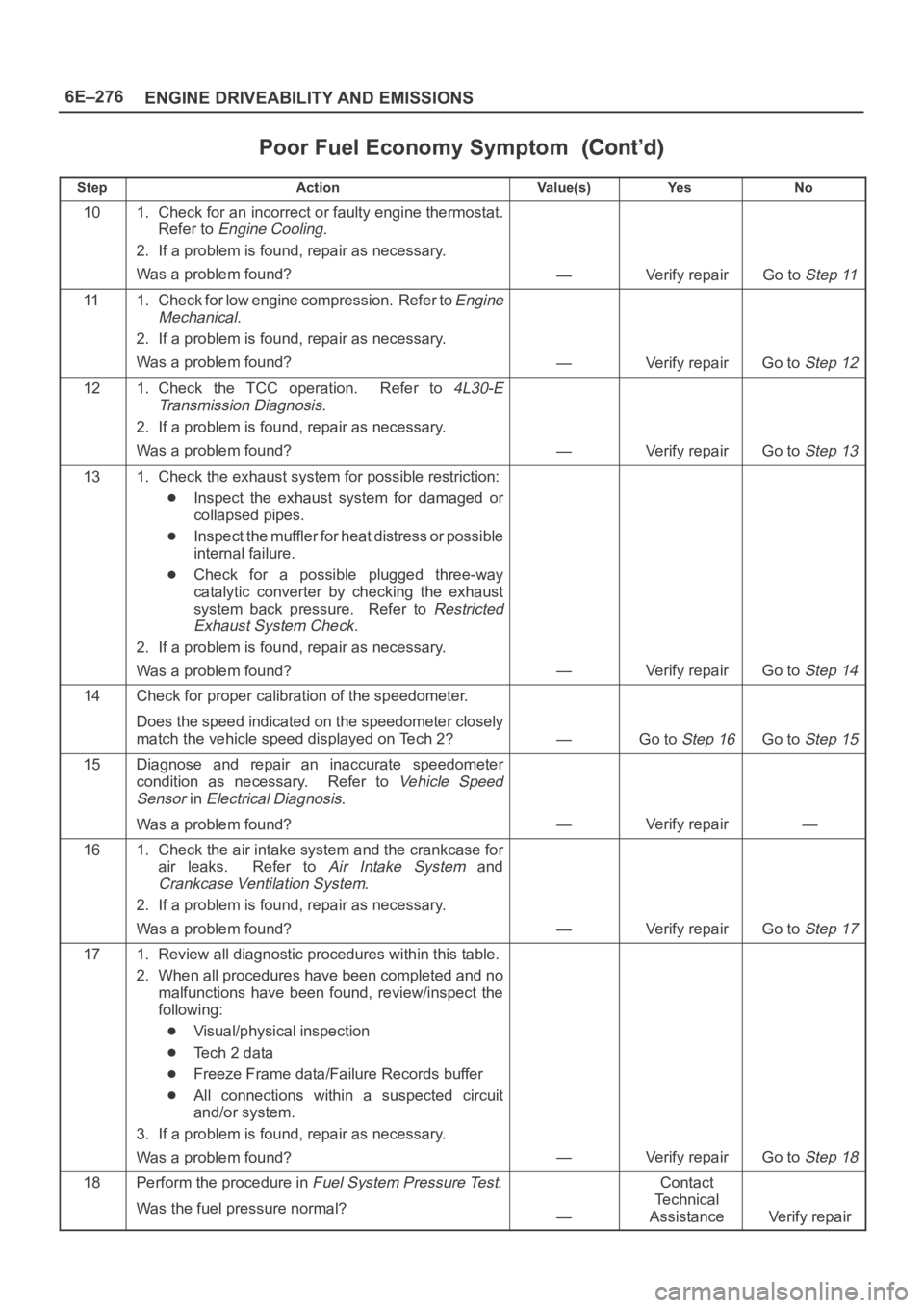
Poor Fuel Economy Symptom
StepNo Ye s Va l u e ( s ) Action
101. Check for an incorrect or faulty engine thermostat.
Refer to
Engine Cooling.
2. If a problem is found, repair as necessary.
Was a problem found?
—Verify repairGo to Step 11
111. Check for low engine compression. Refer to Engine
Mechanical
.
2. If a problem is found, repair as necessary.
Was a problem found?
—Verify repairGo to Step 12
121. Check the TCC operation. Refer to 4L30-E
Transmission Diagnosis
.
2. If a problem is found, repair as necessary.
Was a problem found?
—Verify repairGo to Step 13
131. Check the exhaust system for possible restriction:
Inspect the exhaust system for damaged or
collapsed pipes.
Inspect the muffler for heat distress or possible
internal failure.
Check for a possible plugged three-way
catalytic converter by checking the exhaust
system back pressure. Refer to
Restricted
Exhaust System Check
.
2. If a problem is found, repair as necessary.
Was a problem found?
—Verify repairGo to Step 14
14Check for proper calibration of the speedometer.
Does the speed indicated on the speedometer closely
match the vehicle speed displayed on Tech 2?
—Go to Step 16Go to Step 15
15Diagnose and repair an inaccurate speedometer
condition as necessary. Refer to
Vehicle Speed
Sensor
in Electrical Diagnosis.
Was a problem found?
—Verify repair—
161. Check the air intake system and the crankcase for
air leaks. Refer to
Air Intake System and
Crankcase Ventilation System.
2. If a problem is found, repair as necessary.
Was a problem found?
—Verify repairGo to Step 17
171. Review all diagnostic procedures within this table.
2. When all procedures have been completed and no
malfunctions have been found, review/inspect the
following:
Visual/physical inspection
Te c h 2 d a t a
Freeze Frame data/Failure Records buffer
All connections within a suspected circuit
and/or system.
3. If a problem is found, repair as necessary.
Was a problem found?
—Verify repairGo to Step 18
18Perform the procedure in Fuel System Pressure Test.
Was the fuel pressure normal?
—
Contact
Te c h n i c a l
Assistance
Verify repair
Page 4951 of 6000
6E–294
ENGINE DRIVEABILITY AND EMISSIONS
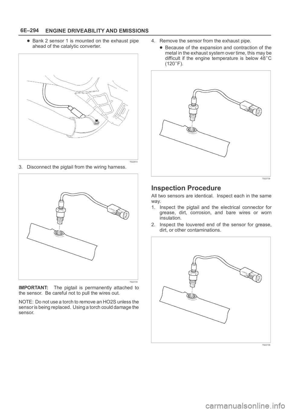
Bank 2 sensor 1 is mounted on the exhaust pipe
ahead of the catalytic converter.
TS22914
3. Disconnect the pigtail from the wiring harness.
TS23739
IMPORTANT:The pigtail is permanently attached to
the sensor. Be careful not to pull the wires out.
NOTE: Do not use a torch to remove an HO2S unless the
sensor is being replaced. Using a torch could damage the
sensor.4. Remove the sensor from the exhaust pipe.
Because of the expansion and contraction of the
metal in the exhaust system over time, this may be
difficult if the engine temperature is below 48
C
(120
F).
TS23739
Inspection Procedure
All two sensors are identical. Inspect each in the same
way.
1. Inspect the pigtail and the electrical connector for
grease, dirt, corrosion, and bare wires or worn
insulation.
2. Inspect the louvered end of the sensor for grease,
dirt, or other contaminations.
TS23739
Page 4982 of 6000
6E–325 ENGINE DRIVEABILITY AND EMISSIONS
Spark Plug Gap Check
Check the gap of all spark plugs before installation.
Use a round wire feeler gauge to ensure an accurate
check.
Plugs installed with the wrong gap can cause poor
engine performance and excessive emissions.
Installation Procedure
NOTE: The plug must thread smoothly into the cylinder
head and be fully seated. Use a thread chaser if
necessary to clean the threads in the cylinder head.
Cross-threading or failure to fully seat the spark plug can
cause plug overheating, exhaust blow-by gas, or thread
damage. Do not overtighten the spark plugs. Over
tightening can cause aluminum threads to strip.
1. Install the spark plug in the engine. Use the
appropriate spark plug socket.
Tighten
Tighten the spark plug to 18 Nꞏm (13 lb ft.).
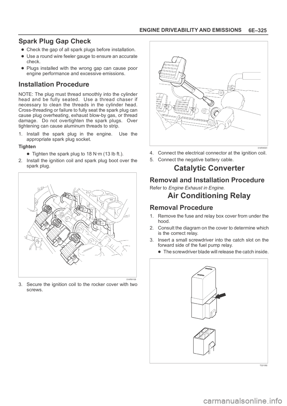
2. Install the ignition coil and spark plug boot over the
spark plug.
014RW108
3. Secure the ignition coil to the rocker cover with two
screws.
014RW091
4. Connect the electrical connector at the ignition coil.
5. Connect the negative battery cable.
Catalytic Converter
Removal and Installation Procedure
Refer to Engine Exhaust in Engine.
Air Conditioning Relay
Removal Procedure
1. Remove the fuse and relay box cover from under the
hood.
2. Consult the diagram on the cover to determine which
is the correct relay.
3. Insert a small screwdriver into the catch slot on the
forward side of the fuel pump relay.
The screwdriver blade will release the catch inside.
T321092
Page 4999 of 6000

6E–342
ENGINE DRIVEABILITY AND EMISSIONS
PCM to calculate true sequential multiport fuel injection
(SFI). Loss of this signal will set a DTC P0341. If the CMP
signal is lost while the engine is running, the fuel injection
system will shift to a calculated sequential fuel injection
based on the last fuel injection pulse, and the engine will
continue to run. The engine can be restarted and will run
in the calculated sequential mode as long as the fault is
present, with a 1-in-6 chance of being correct.
Clear Flood Mode
Clear a flooded engine by pushing the accelerator pedal
down all the way. The PCM then de-energizes the fuel
injectors. The PCM holds the fuel injectors de-energized
as long as the throttle remains above 80% and the engine
speed is below 800 RPM. If the throttle position becomes
less than 80%, the PCM again begins to pulse the
injectors “ON” and “OFF,” allowing fuel into the cylinders.
Deceleration Mode
The PCM reduces the amount of fuel injected when it
detects a decrease in the throttle position and the air flow.
When deceleration is very fast, the PCM may cut off fuel
completely for short periods.
Engine Speed/Vehicle Speed/Fuel Disable
Mode
The PCM monitors engine speed. It turns off the fuel
injectors when the engine speed increase above 6400
RPM. The fuel injectors are turned back on when engine
speed decreases below 6150 RPM.
Fuel Cutoff Mode
No fuel is delivered by the fuel injectors when the ignition
is “OFF.” This prevents engine run-on. In addition, the
PCM suspends fuel delivery if no reference pulses are
detected (engine not running) to prevent engine flooding.
Fuel Injector
The sequential multiport fuel injection (SFI) fuel injector is
a solenoid-operated device controlled by the PCM. The
PCM energizes the solenoid, which opens a valve to allow
fuel delivery.
The fuel is injected under pressure in a conical spray
pattern at the opening of the intake valve. Excess fuel not
used by the injectors passes through the fuel pressure
regulator before being returned to the fuel tank.
A fuel injector which is stuck partly open will cause a loss
of fuel pressure after engine shut down, causing long
crank times.
0003
Fuel Metering System Components
The fuel metering system is made up of the following
parts:
The fuel injectors.
The throttle body.
The fuel rail.
The fuel pressure regulator.
The PCM.
The crankshaft position (CKP) sensor.
The camshaft position (CMP) sensor.
The idle air control (IAC) valve.
The fuel pump.
The fuel pump relay.
Basic System Operation
The fuel metering system starts with the fuel in the fuel
tank. An electric fuel pump, located in the fuel tank,
pumps fuel to the fuel rail through an in-line fuel filter. The
pump is designed to provide fuel at a pressure above the
pressure needed by the injectors. A fuel pressure
regulator in the fuel rail keeps fuel available to the fuel
injectors at a constant pressure. A return line delivers
unused fuel back to the fuel tank. Refer to
Section 6C f o r
further information on the fuel tank, line filter, and fuel
pipes.
Fuel Metering System Purpose
The basic function of the air/fuel metering system is to
control the air/fuel delivery to the engine. Fuel is delivered
to the engine by individual fuel injectors mounted in the
intake manifold near each intake valve.
The main control sensor is the heated oxygen sensor
(HO2S) located in the exhaust system. The HO2S tells
the PCM how much oxygen is in the exhaust gas. The
PCM changes the air/fuel ratio to the engine by controlling
the amount of time that fuel injector is “ON.” The best
mixture to minimize exhaust emissions is 14.7 parts of air
to 1 part of gasoline by weight, which allows the catalytic
converter to operate most efficiently. Because of the