1998 OPEL FRONTERA Electrical
[x] Cancel search: ElectricalPage 1890 of 6000

ENGINE ELECTRICAL 6D – 23
QOS4 PREHEATING SYSTEM
GENERAL DESCRIPTION
QOS4 preheating system features a quick-on glow plug
with thermometer control of the glowing time and the
afterglow time function.
The system consists of the ECM, indicator lamp, ECT
sensor, vehicle speed sensor, relay and temperature
self-control type glow plugs.With the employment of the ECT sensor, the glow time
changes according to the engine coolant temperature,
thus allowing optimum starting conditions to be
obtained.
The after glow time function is controlled by ECM.
NOTE:
Refer to DTC P0380 and P0381 of 6E section.
SYSTEM DIAGRAM
+
-KEY
50A
ECM
50A
GLOW
50A
2
WHT/
RED
0.5
BLK/
BLU
ECM J1-15 3
WHT/
RED
3
RED/
BLKMAIN
80A
8BLK/RED
Glow
Relay
GLOW PLUG 4
BATTHeater & A/C
Relay
060RW132
Page 1891 of 6000
6D – 24 ENGINE ELECTRICAL
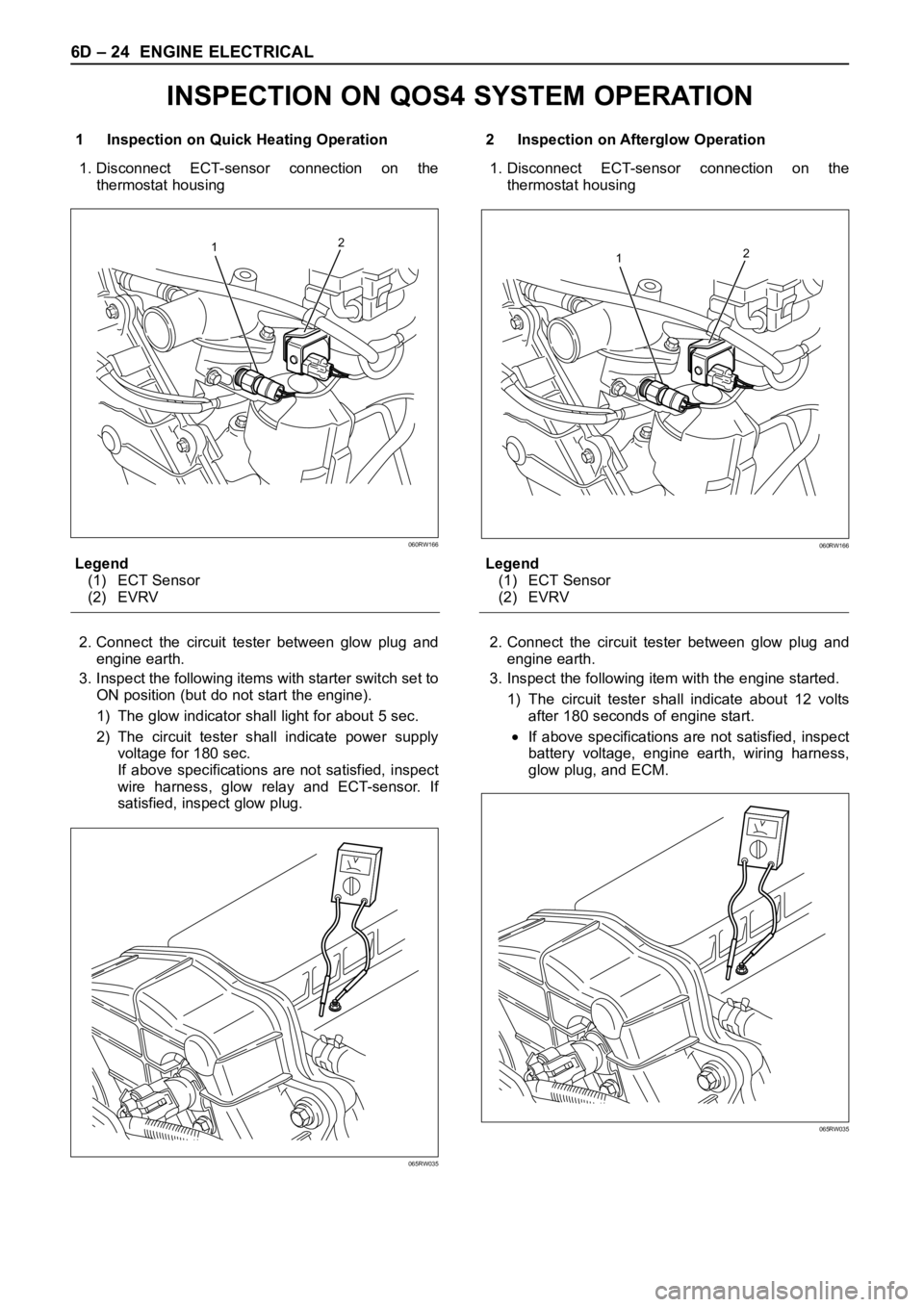
1 Inspection on Quick Heating Operation
1. Disconnect ECT-sensor connection on the
thermostat housing
Legend
(1) ECT Sensor
(2) EVRV
2. Connect the circuit tester between glow plug and
engine earth.
3. Inspect the following items with starter switch set to
ON position (but do not start the engine).
1) The glow indicator shall light for about 5 sec.
2) The circuit tester shall indicate power supply
voltage for 180 sec.
If above specifications are not satisfied, inspect
wire harness, glow relay and ECT-sensor. If
satisfied, inspect glow plug.2 Inspection on Afterglow Operation
1. Disconnect ECT-sensor connection on the
thermostat housing
Legend
(1) ECT Sensor
(2) EVRV
2. Connect the circuit tester between glow plug and
engine earth.
3. Inspect the following item with the engine started.
1) The circuit tester shall indicate about 12 volts
after 180 seconds of engine start.
If above specifications are not satisfied, inspect
battery voltage, engine earth, wiring harness,
glow plug, and ECM.
12
060RW166
065RW035
12
060RW166
065RW035
INSPECTION ON QOS4 SYSTEM OPERATION
Page 1892 of 6000

ENGINE ELECTRICAL 6D – 25
ECT SENSOR
Measure the resistance depending on the water
temperature.
Temperature (°C) Current (mA) Resistance (k
)
20 ± 1 1.0 2.0 – 3.0
50 ± 1 1.0 0.6 – 1.0
When installing the ECT sensor, apply sealant (Loctite
#262 or equivalent) to prevent water leakage.
Torque: 8 Nꞏm (0.8 kgꞏm/69 lb in)
Legend
(1) Sealing Material
GLOW PLUG
Inspect the resistance
Resistance at normal temperature: 0.8 – 1.0
Torque: 23 Nꞏm (2.3 kgꞏm/17 lbꞏft)
GLOW PLUG RELAY
Inspect the continuity
(2) – (4) No Continuity
(1) – (3) Continuity
If battery voltage is applied to the terminal between (1)
– (3)
(2) – (4) Continuity065RW058
065RW061
1
065RW060
2 42
311
34
065RW037
Page 1899 of 6000
6E–6
4JX1–TC ENGINE DRIVEABILITY AND EMISSIONS
Removal Procedure 6E–212. . . . . . . . . . . . . . . . . . . .
Installation Procedure 6E–212. . . . . . . . . . . . . . . . . .
Fuel Filter Cap 6E–213. . . . . . . . . . . . . . . . . . . . . . . . . .
General Description 6E–213. . . . . . . . . . . . . . . . . . . .
Inspection Procedure 6E–213. . . . . . . . . . . . . . . . . .
Fuel Filter 6E–213. . . . . . . . . . . . . . . . . . . . . . . . . . . . . .
Removal and Installation Procedure 6E–213. . . . . .
Fuel Gauge Unit 6E–213. . . . . . . . . . . . . . . . . . . . . . . .
Removal Procedure 6E–213. . . . . . . . . . . . . . . . . . . .
Installation Procedure 6E–214. . . . . . . . . . . . . . . . . .
Fuel Injectors 6E–214. . . . . . . . . . . . . . . . . . . . . . . . . . .
Removal and Installation Procedure 6E–214. . . . . .
Fuel Temperature Sensor 6E–214. . . . . . . . . . . . . . . .
Removal Procedure 6E–214. . . . . . . . . . . . . . . . . . . .
Installation Procedure 6E–215. . . . . . . . . . . . . . . . . .
Rail Pressure (RP) Sensor 6E–216. . . . . . . . . . . . . . .
Removal Procedure 6E–216. . . . . . . . . . . . . . . . . . . .
Installation Procedure 6E–216. . . . . . . . . . . . . . . . . .
Fuel Tank 6E–216. . . . . . . . . . . . . . . . . . . . . . . . . . . . . .
Removal Procedure 6E–216. . . . . . . . . . . . . . . . . . . .
Throttle Body (TB) 6E–217. . . . . . . . . . . . . . . . . . . . . . .
Removal Procedure 6E–217. . . . . . . . . . . . . . . . . . . .
Installation Procedure 6E–217. . . . . . . . . . . . . . . . . .
Air Conditioning (A/C) Relay 6E–217. . . . . . . . . . . . . .
Removal Procedure 6E–217. . . . . . . . . . . . . . . . . . . .
Installation Procedure 6E–217. . . . . . . . . . . . . . . . . .
Exhaust Gas Recirculation (EGR) Vacuum
Switch Valve (VSV) 6E–217. . . . . . . . . . . . . . . . . . . . .
Removal Procedure 6E–217. . . . . . . . . . . . . . . . . . . .
Installation Procedure 6E–218. . . . . . . . . . . . . . . . . .
Electronic Vacuum Regurating Valve (EVRV) 6E–219
Removal Procedure 6E–219. . . . . . . . . . . . . . . . . . . .
Installation Procedure 6E–220. . . . . . . . . . . . . . . . . .
Wiring and Connectors 6E–220. . . . . . . . . . . . . . . . . . .
Wiring Harness Service 6E–220. . . . . . . . . . . . . . . .
Connectors and Terminals 6E–220. . . . . . . . . . . . . .
Wire Harness Repair: Twisted Shielded
Cable 6E–220. . . . . . . . . . . . . . . . . . . . . . . . . . . . . . . . .
Removal Procedure 6E–220. . . . . . . . . . . . . . . . . . . .
Installation Procedure 6E–221. . . . . . . . . . . . . . . . . .
Twisted Leads 6E–221. . . . . . . . . . . . . . . . . . . . . . . . . .
Removal Procedure 6E–221. . . . . . . . . . . . . . . . . . . .
Installation Procedure 6E–222. . . . . . . . . . . . . . . . . .
Weather-Pack Connector 6E–223. . . . . . . . . . . . . . . . .
Tools Required 6E–223. . . . . . . . . . . . . . . . . . . . . . . .
Removal Procedure 6E–223. . . . . . . . . . . . . . . . . . . . Installation Procedure 6E–223. . . . . . . . . . . . . . . . . .
Com-Pack III 6E–224. . . . . . . . . . . . . . . . . . . . . . . . . . .
General Information 6E–224. . . . . . . . . . . . . . . . . . . .
Metri-Pack 6E–224. . . . . . . . . . . . . . . . . . . . . . . . . . . . .
Tools Required 6E–224. . . . . . . . . . . . . . . . . . . . . . . .
Removal Procedure 6E–224
. . . . . . . . . . . . . . . . . . . .
Installation Procedure 6E–224. . . . . . . . . . . . . . . . . .
General Description
(ECM and Sensors) 6E–225. . . . . . . . . . . . . . . . . . . . .
57X Reference ECM Input 6E–225. . . . . . . . . . . . . .
A/C Request Signal 6E–225. . . . . . . . . . . . . . . . . . . .
Crankshaft Position (CKP) Sensor 6E–225. . . . . . .
Camshaft Position (CMP) Sensor and
Signal 6E–225. . . . . . . . . . . . . . . . . . . . . . . . . . . . . . .
Engine Coolant Temperature (ECT) Sensor 6E–225
Electrically Erasable Programmable Read
Only Memory (EEPROM) 6E–225. . . . . . . . . . . . . .
Intake Air Temperature (IAT) Sensor 6E–225. . . . .
Manifold Absolute Pressure (MAP) Sensor 6E–226
Engine Control Module (ECM) 6E–226. . . . . . . . . . .
ECM Function 6E–226. . . . . . . . . . . . . . . . . . . . . . . . .
ECM Components 6E–226. . . . . . . . . . . . . . . . . . . . .
ECM Voltage Description 6E–226. . . . . . . . . . . . . . .
ECM Input/Outputs 6E–226. . . . . . . . . . . . . . . . . . . .
ECM Service Precautions 6E–227. . . . . . . . . . . . . .
Intake Throttle Position (ITP) Sensor 6E–227. . . . .
Transmission Range Switch 6E–227. . . . . . . . . . . . .
Accelerator Position Sensor (AP) 6E–227. . . . . . . .
Aftermarket Electrical and Vacuum
Equipment 6E–227. . . . . . . . . . . . . . . . . . . . . . . . . . .
Electrostatic Discharge Damage 6E–227. . . . . . . . .
General Description (Air Induction) 6E–228. . . . . . . .
Air Induction System 6E–228. . . . . . . . . . . . . . . . . . .
General Description (Fuel Metering) 6E–228. . . . . . .
Deceleration Mode 6E–228. . . . . . . . . . . . . . . . . . . .
Fuel Injector 6E–228. . . . . . . . . . . . . . . . . . . . . . . . . .
Fuel Metering System Components 6E–228. . . . . .
A/C Clutch Diagnosis 6E–228. . . . . . . . . . . . . . . . . . . .
A/C Request Signal 6E–228. . . . . . . . . . . . . . . . . . . .
General Description Exhaust Gas
Recirculation (EGR) System 6E–228. . . . . . . . . . . . .
EGR Purpose 6E–228. . . . . . . . . . . . . . . . . . . . . . . . .
Fuse and Relay Panel
(Underhood Electrical Center) RHD 6E–229. . . . . . .
Fuse and Relay Panel
(Underhood Electrical Center) LHD 6E–230. . . . . . .
Page 1917 of 6000
6E–24
4JX1–TC ENGINE DRIVEABILITY AND EMISSIONS
Diagnosis
Strategy-Based Diagnostics
Strategy-Based Diagnostics
The strategy-based diagnostic is a uniform approach to
repair all Electrical/Electronic (E/E) systems. The
diagnostic flow can always be used to resolve an E/E
system problem and is a starting point when repairs are
necessary. The following steps will instruct the technician
how to proceed with a diagnosis:
1. Verify the customer complaint.
To verify the customer complaint, the technician
should know the normal operation of the system.
2. Perform preliminary checks.
Conduct a thorough visual inspection.
Review the service history.
Detect unusual sounds or odors.
Gather diagnostic trouble code information to
achieve an effective repair.
3. Check bulletins and other service information.
This includes videos, newsletters, etc.
4. Refer to service information (manual) system
check(s).
“System checks” contain information on a system
that may not be supported by one or more DTCs.
System checks verify proper operation of the
system. This will lead the technician in an
organized approach to diagnostics.
5. Refer to service diagnostics.
DTC Stored
Follow the designated DTC chart exactly to make an
effective repair.
No DTC
Select the symptom from the symptom tables. Follow the
diagnostic paths or suggestions to complete the repair.
You may refer to the applicable component/system check
in the system checks.
No Matching Symptom
1. Analyze the complaint.
2. Develop a plan for diagnostics.
3. Utilize the wiring diagrams and the theory of
operation.
Call technical assistance for similar cases where repair
history may be available. Combine technician knowledge
with efficient use of the available service information.
Intermittents
Conditions that are not always present are called
intermittents. To resolve intermittents, perform the
following steps:
1. Observe history DTCs, DTC modes, and freezeframe
data.2. Evaluate the symptoms and the conditions described
by the customer.
3. Use a check sheet or other method to identify the
circuit or electrical system component.
4. Follow the suggestions for intermittent diagnosis
found in the service documentation.
Most scan tools, such as the Tech 2 and the DVM, have
data-capturing capabilities that can assist in detecting
intermittents.
No Trouble Found
This condition exists when the vehicle is found to operate
normally. The condition described by the customer may
be normal. Verify the customer complaint against another
vehicle that is operating normally. The condition may be
intermittent. Verify the complaint under the conditions
described by the customer before releasing the vehicle.
1. Re-examine the complaint.
When the complaint cannot be successfully found or
isolated, a re-evaluation is necessary. The complaint
should be re-verified and could be intermittent as
defined in
Intermittents, or could be normal.
2. Repair and verify.
After isolating the cause, the repairs should be made.
Validate for proper operation and verify that the
symptom has been corrected. This may involve road
testing or other methods to verify that the complaint
has been resolved under the following conditions:
Conditions noted by the customer.
If a DTC was diagnosed, verify a repair by
duplicating conditions present when the DTC was
set as noted in the Failure Records or Freeze
Frame data.
Verifying Vehicle Repair
Verification of the vehicle repair will be more
comprehensive for vehicles with OBD system
diagnostics. Following a repair, the technician should
perform the following steps:
IMPORTANT:Follow the steps below when you verify
repairs on OBD systems. Failure to follow these steps
could result in unnecessary repairs.
1. Review and record the Failure Records and the
Freeze Frame data for the DTC which has been
diagnosed (Freeze Frame data will only be stored for
the MIL (“Check Engine” lamp) has been requested).
2. Clear the DTC(s).
3. Operate the vehicle within conditions noted in the
Failure Records and Freeze Frame data.
4. Monitor the DTC status information for the specific
DTC which has been diagnosed until the diagnostic
test associated with that DTC runs.
Page 1939 of 6000
6E–46
4JX1–TC ENGINE DRIVEABILITY AND EMISSIONS
No Malfunction Indicator Lamp (MIL)
StepNo Ye s Va l u e ( s ) Action
15Locate and repair the short to ground in the ECM
ignition feed circuit or ECM battery feed circuit.
Is the action complete?
—Verify repair—
16Locate and repair the short to ground in the ignition
feed circuit to the instrument cluster, and replace the
fuse.
Is the action complete?
—Verify repair—
17Replace the ECM (Refer to the Data Programming in
Case of ECM change).
Is the action complete?
—Verify repair—
18Check the MIL driver circuit for a poor connection at the
instrument panel connector.
Was a problem found?
—Verify repair
Go to
Instrument
Panel
in
Electrical
Diagnosis
Page 1954 of 6000
6E–61 4JX1–TC ENGINE DRIVEABILITY AND EMISSIONS
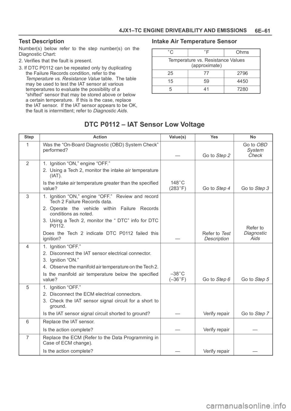
Test Description
Number(s) below refer to the step number(s) on the
Diagnostic Chart:
2. Verifies that the fault is present.
3. If DTC P0112 can be repeated only by duplicating
the Failure Records condition, refer to the
Temperature vs. Resistance Value table. The table
may be used to test the IAT sensor at various
temperatures to evaluate the possibility of a
“shifted” sensor that may be stored above or below
a certain temperature. If this is the case, replace
the IAT sensor. If the IAT sensor appears to be OK,
the fault is intermittent; refer to
Diagnostic Aids.
Intake Air Temperature Sensor
CFOhms
Temperature vs. Resistance Values
(approximate)
25772796
15594450
5417280
DTC P0112 – IAT Sensor Low Voltage
StepActionVa l u e ( s )Ye sNo
1Was the “On-Board Diagnostic (OBD) System Check”
performed?
—Go to Step 2
Go to OBD
System
Check
21. Ignition “ON,” engine “OFF.”
2. Using a Tech 2, monitor the intake air temperature
(IAT).
Is the intake air temperature greater than the specified
value?
148C
(283
F)Go to Step 4Go to Step 3
31. Ignition “ON,” engine “OFF.” Review and record
Tech 2 Failure Records data.
2. Operate the vehicle within Failure Records
conditions as noted.
3. Using a Tech 2, monitor the “ DTC” info for DTC
P0112.
Does the Tech 2 indicate DTC P0112 failed this
ignition?
—
Refer to Te s t
Description
Refer to
Diagnostic
Aids
41. Ignition “OFF.”
2. Disconnect the IAT sensor electrical connector.
3. Ignition “ON.”
4. Observe the manifold air temperature on the Tech 2.
Is the manifold air temperature below the specified
value?
–38C
(–36
F)Go to Step 6Go to Step 5
51. Ignition “OFF.”
2. Disconnect the ECM electrical connectors.
3. Check the IAT sensor signal circuit for a short to
ground.
Is the IAT sensor signal circuit shorted to ground?
—Verify repairGo to Step 7
6Replace the IAT sensor.
Is the action complete?
—Verify repair—
7Replace the ECM (Refer to the Data Programming in
Case of ECM change).
Is the action complete?
—Verify repair—
Page 1956 of 6000
6E–63 4JX1–TC ENGINE DRIVEABILITY AND EMISSIONS
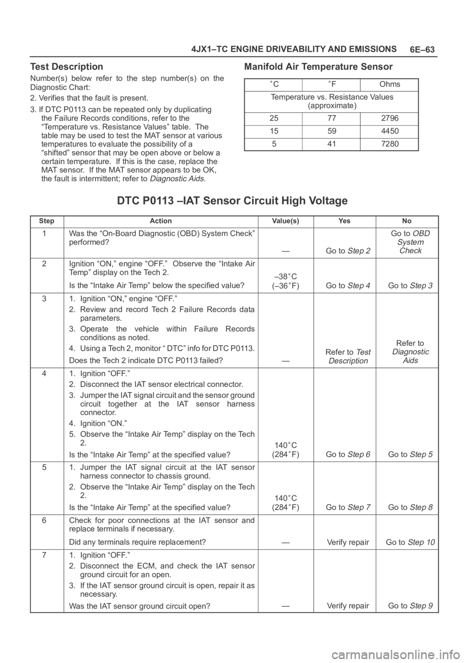
Test Description
Number(s) below refer to the step number(s) on the
Diagnostic Chart:
2. Verifies that the fault is present.
3. If DTC P0113 can be repeated only by duplicating
the Failure Records conditions, refer to the
“Temperature vs. Resistance Values” table. The
table may be used to test the MAT sensor at various
temperatures to evaluate the possibility of a
“shifted” sensor that may be open above or below a
certain temperature. If this is the case, replace the
MAT sensor. If the MAT sensor appears to be OK,
the fault is intermittent; refer to
Diagnostic Aids.
Manifold Air Temperature Sensor
CFOhms
Temperature vs. Resistance Values
(approximate)
25772796
15594450
5417280
DTC P0113 –IAT Sensor Circuit High Voltage
StepActionVa l u e ( s )Ye sNo
1Was the “On-Board Diagnostic (OBD) System Check”
performed?
—Go to Step 2
Go to OBD
System
Check
2Ignition “ON,” engine “OFF.” Observe the “Intake Air
Temp” display on the Tech 2.
Is the “Intake Air Temp” below the specified value?
–38C
(–36
F)Go to Step 4Go to Step 3
31. Ignition “ON,” engine “OFF.”
2. Review and record Tech 2 Failure Records data
parameters.
3. Operate the vehicle within Failure Records
conditions as noted.
4. Using a Tech 2, monitor “ DTC” info for DTC P0113.
Does the Tech 2 indicate DTC P0113 failed?
—
Refer to Te s t
Description
Refer to
Diagnostic
Aids
41. Ignition “OFF.”
2. Disconnect the IAT sensor electrical connector.
3. Jumper the IAT signal circuit and the sensor ground
circuit together at the IAT sensor harness
connector.
4. Ignition “ON.”
5. Observe the “Intake Air Temp” display on the Tech
2.
Is the “Intake Air Temp” at the specified value?
140C
(284
F)Go to Step 6Go to Step 5
51. Jumper the IAT signal circuit at the IAT sensor
harness connector to chassis ground.
2. Observe the “Intake Air Temp” display on the Tech
2.
Is the “Intake Air Temp” at the specified value?
140C
(284
F)Go to Step 7Go to Step 8
6Check for poor connections at the IAT sensor and
replace terminals if necessary.
Did any terminals require replacement?
—Verify repairGo to Step 10
71. Ignition “OFF.”
2. Disconnect the ECM, and check the IAT sensor
ground circuit for an open.
3. If the IAT sensor ground circuit is open, repair it as
necessary.
Was the IAT sensor ground circuit open?
—Verify repairGo to Step 9