1998 OPEL FRONTERA Electrical
[x] Cancel search: ElectricalPage 5776 of 6000
7A–87 AUTOMATIC TRANSMISSION (4L30–E)
(38) Seal, O–Ring
(39) Reservoir
(42) Gasket, Extension Case
(43) Extension Assembly
(44) Seal, O–Ring/Speed Sensor
(45) Sensor Assembly, Speed
(46) Screw, Speed Sensor
(50) Seal, Extension Assembly
(52) Screw, Extension/Main Case
(53) Spring, Parking Pawl Lock
(54) Pawl, Parking Lock
(55) Connector, Electrical/Main Case
(56) Actuator Assembly, Parking Lock
(57) Nut, Parking Lock Lever
(58) Link, Manual Valve
(59) Pin, Spring
(60) Lever, Parking Lock and Range Selector
(61) Shaft, Selector
(62) Seal, Selector Shaft
(63) Mode Switch Assembly
(64) Screw and Conical Washer Assembly
(65) Shield, Mode Switch
(67) Pan, Bottom/Adapter Case
(68) Gasket, Bottom Pan/Adapter Case
(69) Harness Assembly, Adapter Case
(70) Screw, Valve Body
(71) Valve Body Assembly, Adapter Case
(72) Gasket, Adapter Valve Body
(73) Plate, Adapter Valve Body/Transfer
(74) Pan, Bottom/Main Case(75) Gasket, Bottom Pan/Main Case
(76) Gasket, Oil Drain or Overfill Screw
(77) Screw, Oil Drain or Overfill
(78) Magnet, Chip Collector
(79) Filter Oil
(80) Harness Assembly, Main Case
(82) Roller and Spring Assembly, Manual Detent
(84) Valve Body Assembly, Main Case
(85) Ball, Check
(86) Gasket, Main V.B./Transfer Plate
(87) Plate, Main V.B./Transfer
(88) Gasket, Transfer/Main Case
(89) Screw, Transfer Plate on V.B.
(90) Screw, Servo Cover
(91) Cover, Servo Piston
(92) Gasket, Cover/Servo Piston
(93) Ring, Retaining Servo Piston
(94) Clip, Servo Piston
(95) Nut, Servo Screw
(96) Screw, Servo Piston
(97) Piston, Servo
(98) Seal, Ring/Servo Piston
(99) Spring, Cushion/Servo Piston
(100) Seat, Cushion Spring
(101) Sleeve, Servo Piston Adjust
(102) Rod, Apply/Servo Piston
(103) Spring, Return/Servo Piston
(104) Gasket, Adapter Case/Transfer Plate
(105) Powertrain Control Module
(106) Servo Piston Assembly
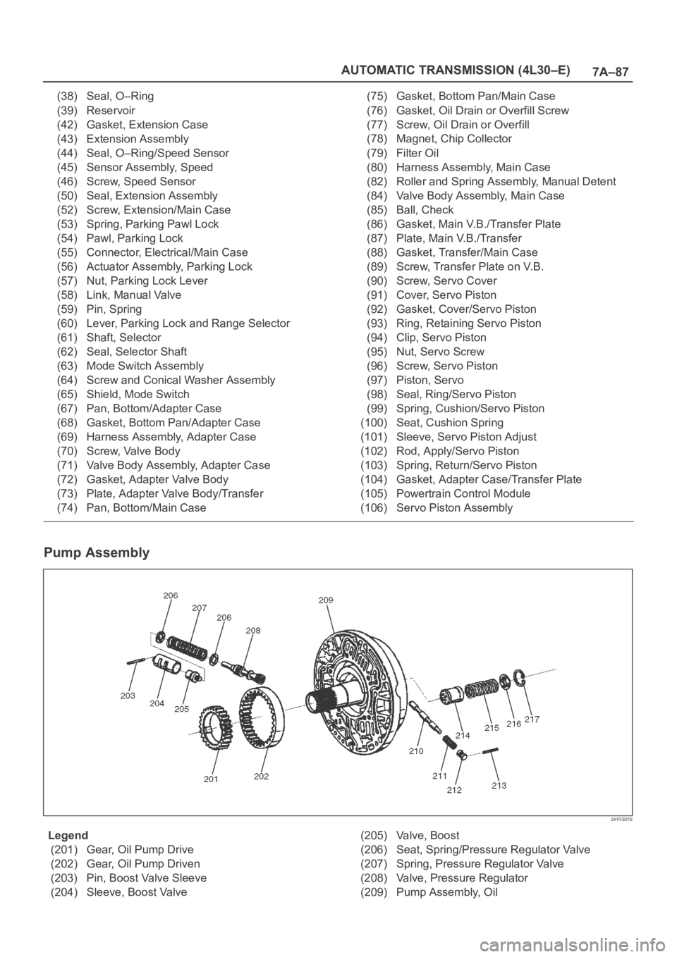
Pump Assembly
241RS019
Legend
(201) Gear, Oil Pump Drive
(202) Gear, Oil Pump Driven
(203) Pin, Boost Valve Sleeve
(204) Sleeve, Boost Valve(205) Valve, Boost
(206) Seat, Spring/Pressure Regulator Valve
(207) Spring, Pressure Regulator Valve
(208) Valve, Pressure Regulator
(209) Pump Assembly, Oil
Page 5794 of 6000
AUTOMATIC TRANSMISSION (AW30-40LE) 7A–13
DIAGNOSIS
BASIC TROUBLESHOOTING
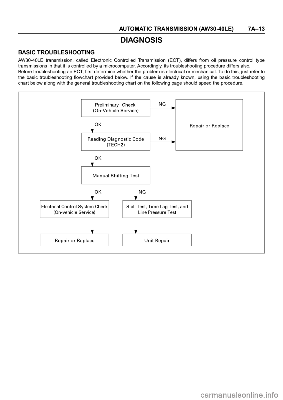
AW30-40LE transmission, called Electronic Controlled Transmission (ECT), differs from oil pressure control type
transmissions in that it is controlled by a microcomputer. Accordingly, its troubleshooting procedure differs also.
Before troubleshooting an ECT, first determine whether the problem is electrical or mechanical. To do this, just refer to
the basic troubleshooting flowchart provided below. If the cause is already known, using the basic troubleshooting
chart below along with the general troubleshooting char t on the following page should speed the procedure.
Page 5798 of 6000

AUTOMATIC TRANSMISSION (AW30-40LE) 7A–17
DIAGNOSIS WITH TECH2
In this AW30-40LE transmission, troubleshooting can be
performed for electrical faults using the Tech2 scan tool.
If the CHECK TRANS lamp blinks, or if an electrical fault in the
transmission may probably exist, check trouble codes using the
Tech2 scan tool.
In the diagnostic procedures described in this manual, first
repair the faulty positions indicated by trouble code in the order
of numbers and then perform troubleshooting for the faulty
positions that are not indicated by trouble code. For correct
troubleshooting, it is necessary to first repair the trouble codes
of lower-order numbers, then to repair the trouble codes of
higher-order numbers in sequence.
How to Use This Manual:
Check trouble codes using the Tech2 scan tool.
If no codes are set:
•Refer to
F1: Data Display and identify the electrical faults
that are not indicated by trouble code.
If codes are set:
• Record all the codes displayed by the Tech2 and check if the
codes are intermittent (intermittent faults).
• Clear the codes.
• Drive the vehicle for a test to reproduce the faulty status.
• Check trouble codes again using the Tech2.
• If no code is displayed by test driving, the fault is intermittent.
In this case, refer to the cautions on intermittent conditions.
• If a code is present, refer to "DIAGNOSTIC TROUBLE
CODES (DTC) CHECK" for diagnosis.
• Because a code of high-order number may be set for the
reason that a code of low-order number has been set after
occurrence of a fault, perform repair work starting with a
lower-order number is ascending order.
Page 5799 of 6000
7A–18 AUTOMATIC TRANSMISSION (AW30-40LE)
901RW176
F07RW033
740RY00013
740RY00014
901RY00014
TECH2 CONNECTION
The Tech2 scan tool is used to electrically diagnose the
automatic transmission system and to check the system. The
Tech2 enhances the diagnosis efficiency though all the
troubleshooting can be done without the Tech2.
The Tech2 is a portable, compact, and light tester. When it is
connected to the diagnosis connector of the vehicle, you can
perform a variety of diagnoses and tests by communicating
with the Transmission Control Module (TCM) of the vehicle.
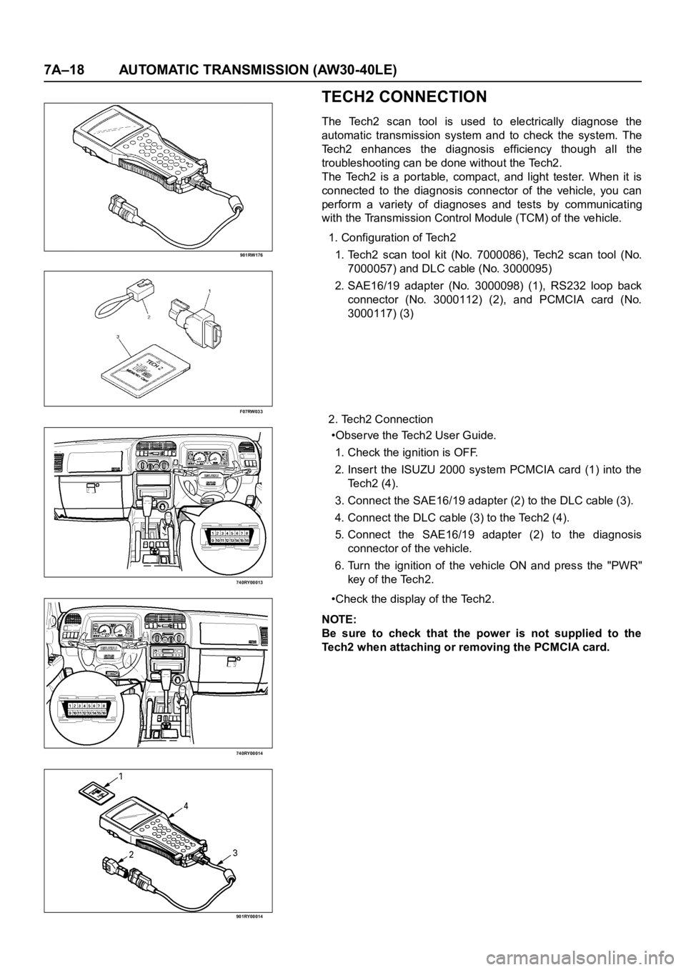
1. Configuration of Tech2
1. Tech2 scan tool kit (No. 7000086), Tech2 scan tool (No.
7000057) and DLC cable (No. 3000095)
2. SAE16/19 adapter (No. 3000098) (1), RS232 loop back
connector (No. 3000112) (2), and PCMCIA card (No.
3000117) (3)
2. Tech2 Connection
•Observe the Tech2 User Guide.
1. Check the ignition is OFF.
2. Inser t the ISUZU 2000 system PCMCIA card (1) into the
Te c h 2 ( 4 ) .
3. Connect the SAE16/19 adapter (2) to the DLC cable (3).
4. Connect the DLC cable (3) to the Tech2 (4).
5. Connect the SAE16/19 adapter (2) to the diagnosis
connector of the vehicle.
6. Turn the ignition of the vehicle ON and press the "PWR"
key of the Tech2.
•Check the display of the Tech2.
NOTE:
Be sure to check that the power is not supplied to the
Tech2 when attaching or removing the PCMCIA card.
Page 5804 of 6000

AUTOMATIC TRANSMISSION (AW30-40LE) 7A–23
INTERMITTENT CONDITIONS
If the Tech2 displays a code as intermittent, or if after a
test drive a code does not reappear, the problem is most
likely a faulty electrical connection or loose wiring.
Terminals should always be the prime suspect.
Intermittent rarely occur in sophisticated electronic
components such as the Transmission Control Module
(TCM).
When an intermittent problem is encountered, check
suspect circuits for:
• Poor terminal to wire connection.
• Terminals not fully seated in the connector body
(backed out).
• Improperly formed or damaged terminals.
• Loose, dirty, or corroded ground connections.
HINT: Any time you have an intermittent in more than
one circuit, check whether the circuits share a
common ground connection.
• Pinched or damaged wires.
• Electro-Magnetic Interference (EMI)
HINT: Check that all wires are properly routed away
from spark plug wires, distributor wires, coil,
and generator. Also check for improperly
installed electrical options, such as lights, 2-
way radios, etc.
Use the F2: SNAPSHOT mode of the Tech2 to help
isolate the cause of an intermittent fault. The snapshot
mode will record information before and after the
problem occurs. Set the snapshot to "trigger" on the
suspect code (or codes) or, if you notice the repor ted
symptom during test drive, trigger the snapshot
manually.
After the snapshot has been triggered, command the
Tech2 to play back the flow of data recorded from each
of the various sensors. Signs of an intermittent fault in a
sensor circuit are a sudden unexplainable jump in data
values out of the normal range.
Page 5843 of 6000
7A–62 AUTOMATIC TRANSMISSION (AW30-40LE)
826RY00018
F07RY00024
MANUAL SHIFTING TEST
NOTE:
With this test, it can be determined whether the trouble lies
within the electrical circuit or is a mechanical problem in
the transmission.
1. Disconnect TCM connector
With the engine OFF, disconnect the TCM connector.
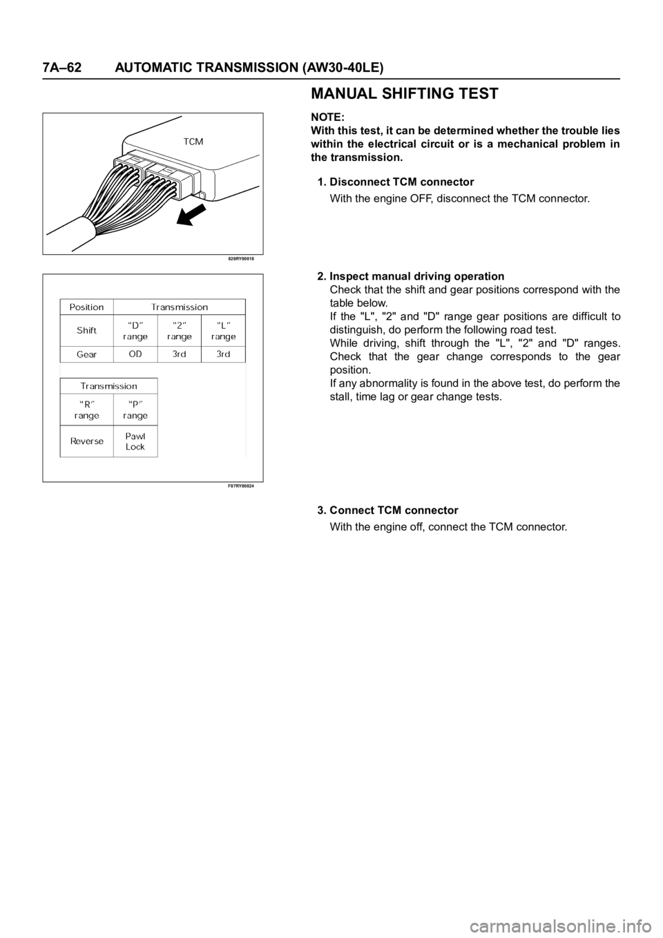
2. Inspect manual driving operation
Check that the shift and gear positions correspond with the
table below.
If the "L", "2" and "D" range gear positions are difficult to
distinguish, do perform the following road test.
While driving, shift through the "L", "2" and "D" ranges.
Check that the gear change corresponds to the gear
position.
If any abnormality is found in the above test, do perform the
stall, time lag or gear change tests.
3. Connect TCM connector
With the engine off, connect the TCM connector.
Page 5853 of 6000

7A–72 AUTOMATIC TRANSMISSION (AW30-40LE)
TCM STANDARD VOLTAGE
Check circuitTe r m i n a l
Measuring condition Voltage (V)
+-
Throttle position sensorC79-6 C79-28Throttle fully opened (WOT) 3.47
4.56
Throttle fully closed (idling) 0.25
0.45
C79-19 C79-18 Key switch ON 4.75
5.25
Output revolution sensor C79-4 C79-16 Engine idling in gear 0
3
Input revolution sensor C79-5 C79-17 Engine idling 0
3
Speed meter sensor C79-7C78-15
or -19Vehicle speed 10
20 km/h Less than 1.4
about 5
Brake switch C78-18C78-15
or -19Depress brake 7
16
Release brake Less than 1
O/D OFF switch C79-3C78-15
or -19O/D OFF switch ON (O/D OFF) 7
16
O/D OFF switch OFF (O/D ON) Less than 1
Neutral start switch
C79-2C78-15
or -19Selector “P” range 7
16
(P) Selector all ranges except “P” Less than 1
Neutral start switch
C79-1C78-15
or -19Selector “R” range 7
16
(R) Selector all ranges except “R” Less than 1
Neutral start switch
C79-9C78-15
or -19Selector “N” range 7
16
(N) Selector all ranges except “N” Less than 1
Neutral start switch
C79-8C78-15
or -19Selector “D” range 7
16
(D) Selector all ranges except “D” Less than 1
Neutral start switch
C79-21C78-15
or -19Selector “2” range 7
16
(2) Selector all ranges except “2” Less than 1
Neutral start switch
C79-20C78-15
or -19Selector “L” range 7
16
(L) Selector all ranges except “L” Less than 1
Engine revolution signal C79-15C78-15
or -19Engine idling Less than 1.4
9 16
Diagnosis terminal C79-24C78-15
or -19Self-diagnosis ON
0
1.5
Power pattern switch C79-23C78-15
or -19Power pattern switch OFF (NORMAL) 8
16
Power pattern switch ON (POWER) Less than 1.4
Winter select switch C79-13C78-15
or -19Switch OFF 8
16
Switch ON Less than 1.4
Electrical source (Battery) C78-13C78-15
or -19—
9
16
Electrical source (Ignition) C78-20C78-15
or -19Key switch ON
9
16
Oil temperature warning lamp C79-11C78-15
or -19Oil temperature warning lamp ON Less than 1
Oil temperature warning lamp OFF 8
16
“CHECK TRANS lamp” C79-10C78-15
or -19“CHECK TRANS” lamp ON Less than 1
“CHECK TRANS” lamp OFF 8
16
Power lamp C79-22C78-15
or -19Power lamp ON Less than 1
Powe r l a m p O F F 8
16
Page 5994 of 6000
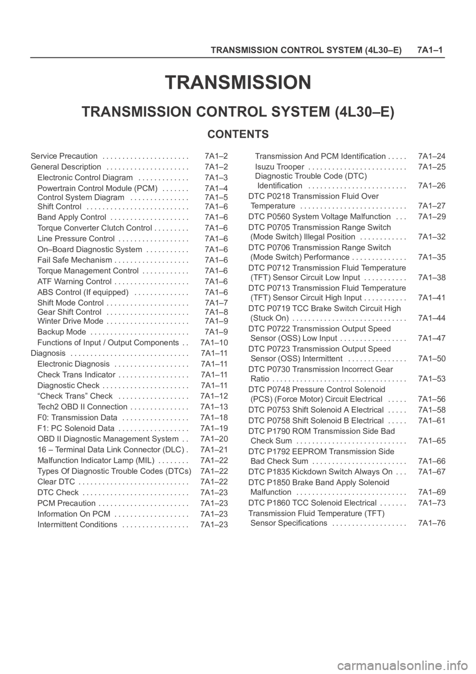
TRANSMISSION CONTROL SYSTEM (4L30–E)7A1–1
TRANSMISSION
TRANSMISSION CONTROL SYSTEM (4L30–E)
CONTENTS
Service Precaution 7A1–2. . . . . . . . . . . . . . . . . . . . . .
General Description 7A1–2. . . . . . . . . . . . . . . . . . . . .
Electronic Control Diagram 7A1–3. . . . . . . . . . . . .
Powertrain Control Module (PCM) 7A1–4. . . . . . .
Control System Diagram 7A1–5. . . . . . . . . . . . . . .
Shift Control 7A1–6. . . . . . . . . . . . . . . . . . . . . . . . . .
Band Apply Control 7A1–6. . . . . . . . . . . . . . . . . . . .
Torque Converter Clutch Control 7A1–6. . . . . . . . .
Line Pressure Control 7A1–6. . . . . . . . . . . . . . . . . .
On–Board Diagnostic System 7A1–6. . . . . . . . . . .
Fail Safe Mechanism 7A1–6. . . . . . . . . . . . . . . . . . .
Torque Management Control 7A1–6. . . . . . . . . . . .
ATF Warning Control 7A1–6. . . . . . . . . . . . . . . . . . .
ABS Control (If equipped) 7A1–6. . . . . . . . . . . . . .
Shift Mode Control 7A1–7. . . . . . . . . . . . . . . . . . . . .
Gear Shift Control 7A1–8. . . . . . . . . . . . . . . . . . . . .
Winter Drive Mode 7A1–9. . . . . . . . . . . . . . . . . . . . .
Backup Mode 7A1–9. . . . . . . . . . . . . . . . . . . . . . . . .
Functions of Input / Output Components 7A1–10. .
Diagnosis 7A1–11. . . . . . . . . . . . . . . . . . . . . . . . . . . . . .
Electronic Diagnosis 7A1–11. . . . . . . . . . . . . . . . . . .
Check Trans Indicator 7A1–11. . . . . . . . . . . . . . . . . .
Diagnostic Check 7A1–11. . . . . . . . . . . . . . . . . . . . . .
“Check Trans” Check 7A1–12. . . . . . . . . . . . . . . . . .
Tech2 OBD II Connection 7A1–13. . . . . . . . . . . . . . .
F0: Transmission Data 7A1–18. . . . . . . . . . . . . . . . .
F1: PC Solenoid Data 7A1–19. . . . . . . . . . . . . . . . . .
OBD II Diagnostic Management System 7A1–20. .
16 – Terminal Data Link Connector (DLC) 7A1–21.
Malfunction Indicator Lamp (MIL) 7A1–22. . . . . . . .
Types Of Diagnostic Trouble Codes (DTCs) 7A1–22
Clear DTC 7A1–22. . . . . . . . . . . . . . . . . . . . . . . . . . . .
DTC Check 7A1–23. . . . . . . . . . . . . . . . . . . . . . . . . . .
PCM Precaution 7A1–23. . . . . . . . . . . . . . . . . . . . . . .
Information On PCM 7A1–23. . . . . . . . . . . . . . . . . . .
Intermittent Conditions 7A1–23. . . . . . . . . . . . . . . . . Transmission And PCM Identification 7A1–24. . . . .
Isuzu Trooper 7A1–25. . . . . . . . . . . . . . . . . . . . . . . . .
Diagnostic Trouble Code (DTC)
Identification 7A1–26. . . . . . . . . . . . . . . . . . . . . . . . .
DTC P0218 Transmission Fluid Over
Temperature 7A1–27. . . . . . . . . . . . . . . . . . . . . . . . . . .
DTC P0560 System Voltage Malfunction 7A1–29. . .
DTC P0705 Transmission Range Switch
(Mode Switch) Illegal Position 7A1–32. . . . . . . . . . . .
DTC P0706 Transmission Range Switch
(Mode Switch) Performance 7A1–35. . . . . . . . . . . . . .
DTC P0712 Transmission Fluid Temperature
(TFT) Sensor Circuit Low Input 7A1–38. . . . . . . . . . .
DTC P0713 Transmission Fluid Temperature
(TFT) Sensor Circuit High Input 7A1–41. . . . . . . . . . .
DTC P0719 TCC Brake Switch Circuit High
(Stuck On) 7A1–44. . . . . . . . . . . . . . . . . . . . . . . . . . . . .
DTC P0722 Transmission Output Speed
Sensor (OSS) Low Input 7A1–47
. . . . . . . . . . . . . . . . .
DTC P0723 Transmission Output Speed
Sensor (OSS) Intermittent 7A1–50. . . . . . . . . . . . . . .
DTC P0730 Transmission Incorrect Gear
Ratio 7A1–53. . . . . . . . . . . . . . . . . . . . . . . . . . . . . . . . . .
DTC P0748 Pressure Control Solenoid
(PCS) (Force Motor) Circuit Electrical 7A1–56. . . . .
DTC P0753 Shift Solenoid A Electrical 7A1–58. . . . .
DTC P0758 Shift Solenoid B Electrical 7A1–61. . . . .
DTC P1790 ROM Transmission Side Bad
Check Sum 7A1–65. . . . . . . . . . . . . . . . . . . . . . . . . . . .
DTC P1792 EEPROM Transmission Side
Bad Check Sum 7A1–66. . . . . . . . . . . . . . . . . . . . . . . .
DTC P1835 Kickdown Switch Always On 7A1–67. . .
DTC P1850 Brake Band Apply Solenoid
Malfunction 7A1–69. . . . . . . . . . . . . . . . . . . . . . . . . . . .
DTC P1860 TCC Solenoid Electrical 7A1–73. . . . . . .
Transmission Fluid Temperature (TFT)
Sensor Specifications 7A1–76. . . . . . . . . . . . . . . . . . .