1998 OPEL FRONTERA Electrical
[x] Cancel search: ElectricalPage 5694 of 6000
7A–5 AUTOMATIC TRANSMISSION (4L30–E)
Normal Operation Of 2000 4L30–E
Tr a n s m i s s i o n
Torque Converter Clutch (TCC)
Application Conditions:
The TCC is normally applied in 2nd, 3rd and 4th gears
only when all of the following conditions exist:
— The engine coolant temperature is above 70
C
(158
F).
— The brake pedal is released.
— The shift pattern requests TCC apply.
Moreover, TCC is always applied in 2nd, 3rd and 4th
gears when the transmission oil temperature is above
135
C (275F).
This mode should be canceled at 125
C (257F).
ATF Warning Lamp
The ATF warning lamp will be constantly on (not flashing)
if the transmission oil temperature is above 145
C
(293
F).
The ATF warning lamp goes off again when the
transmission oil temperature is below 125
C (257F).
Special Shift Pattern When The Engine Is
Cold:
A special shift pattern is activated when the engine
coolant temperature is below 70
C (158F). (3–4 shifts,
for example, are delayed for small throttle openings and
will occur a few MPH higher.)
Diagnosis
Introduction
The systematic troubleshooting information covered by
this Section offers a practical and systematic approach to
diagnosing 4L30–E transmission, using information that
can be obtained from road tests, electrical diagnosis, oil
pressure checks or noise evaluation.
The key to correcting a complaint is to make use of all of
the available symptoms and logically letting them direct
you to the cause.
When dealing with automatic transmission complaints, it
is best to gather as many symptoms as possible before
making the decision to remove the transmission from the
vehicle.
Frequently, the correction of the complaint does not
require removal of the transmission from the vehicle.
Driver Information
To analyze the problem fill out a complete description of
the owner’s complaint.
Please draw a circle around the right information and
complete the following form. (The next page is an
example of a completed form). You can draw a circle
around many numbers if you are not sure.
Page 5711 of 6000
7A–22
AUTOMATIC TRANSMISSION (4L30–E)
Chart 16: Possible Causes Of
Transmission Fluid Leaks
Before attempting to correct an oil leak, the actual source
of the leak must be determined. In many cases, the
source of the leak may be difficult to determine due to
“wind flow” around the engine and transmission.
The suspected area should be wiped clean before in-
specting for the source of the leak.Oil leaks around the engine and transmission are gener-
ally carried toward the rear of the vehicle by the air
stream. In determining the source of an leak, the following
two checks should be made:
1. With the engine running, check for external line
pressure leaks.
2. With the engine off, check for oil leaks due to the
raised oil level caused by drainback of converter oil
into the transmission.
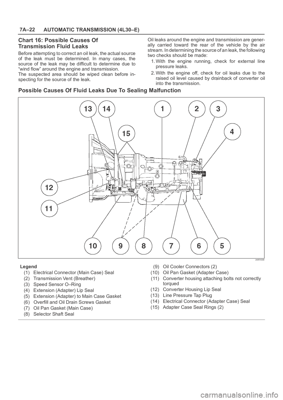
Possible Causes Of Fluid Leaks Due To Sealing Malfunction
240RX008
Legend
(1) Electrical Connector (Main Case) Seal
(2) Transmission Vent (Breather)
(3) Speed Sensor O–Ring
(4) Extension (Adapter) Lip Seal
(5) Extension (Adapter) to Main Case Gasket
(6) Overfill and Oil Drain Screws Gasket
(7) Oil Pan Gasket (Main Case)
(8) Selector Shaft Seal(9) Oil Cooler Connectors (2)
(10) Oil Pan Gasket (Adapter Case)
(11) Converter housing attaching bolts not correctly
torqued
(12) Converter Housing Lip Seal
(13) Line Pressure Tap Plug
(14) Electrical Connector (Adapter Case) Seal
(15) Adapter Case Seal Rings (2)
Page 5721 of 6000
7A–32
AUTOMATIC TRANSMISSION (4L30–E)
h. Reinstall the selector lever.
249RW001
Procedure 2
a. Place selector lever in neutral.
b. Disconnect transmission harness connector from
mode switch connector.
c. Remove mode switch connector with bracket from
the transmission case.
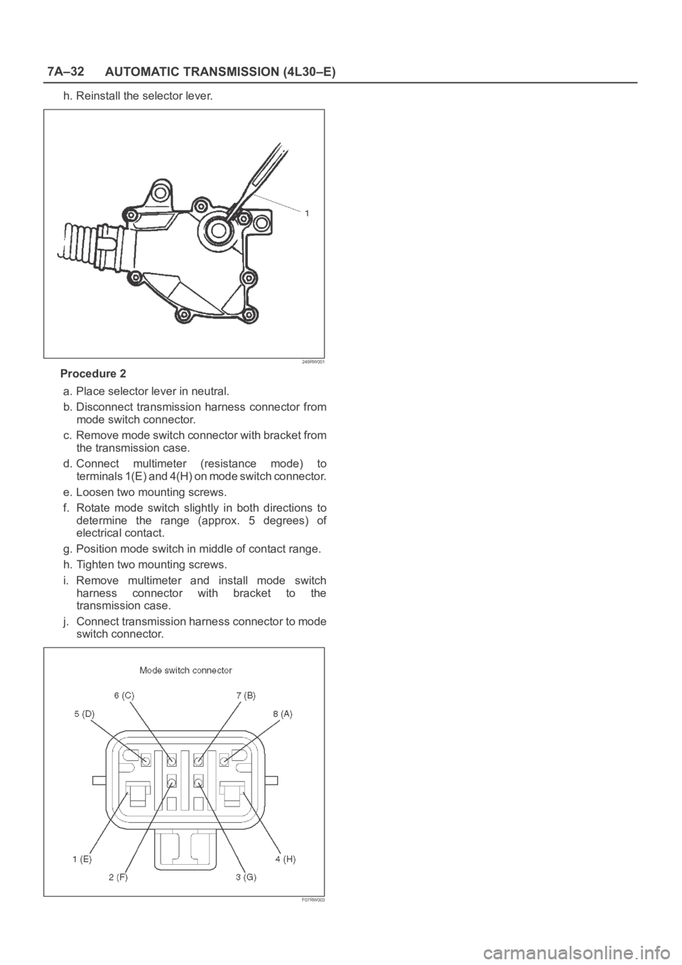
d. Connect multimeter (resistance mode) to
terminals 1(E) and 4(H) on mode switch connector.
e. Loosen two mounting screws.
f. Rotate mode switch slightly in both directions to
determine the range (approx. 5 degrees) of
electrical contact.
g. Position mode switch in middle of contact range.
h. Tighten two mounting screws.
i. Remove multimeter and install mode switch
harness connector with bracket to the
transmission case.
j. Connect transmission harness connector to mode
switch connector.
F07RW003
Page 5730 of 6000
7A–41 AUTOMATIC TRANSMISSION (4L30–E)
Valve Body Assembly (Main Case)
Removal
1. Raise the vehicle and support it on jack stands.
2. Disconnect battery ground cable.
3. Remove transfer and exhaust protectors.
4. Drain fluid.
5. Remove exhaust pipe and disconnect oxygen sensor
connector.
6. Support transfer case with a jack and remove third
crossmember.
7. Remove sixteen 10 mm screws, main case oil pan,
magnet and gasket.
8. Remove three 13 mm oil filter fixing screws, then
remove oil filter.
9. Remove two 13 mm manual detent fixing screws,
then remove roller and spring assembly.
10. Disconnect wiring harness from band control
solenoid and shift solenoids. Pull only on connectors,
not on wiring harness.
11. Remove four 13 mm servo cover fixing screws, then
remove servo cover and gasket.
12. Remove seven 13 mm valve body fixing screws.
Disconnect the ground wire from the main case
valve body.
13. Remove main case valve body with manual valve link
and transfer plate. Note the position of the link (long
end into valve, short end into range selector lever).
14. Remove transfer plate gasket from main case.
15. Remove two check balls from main case.
Installation
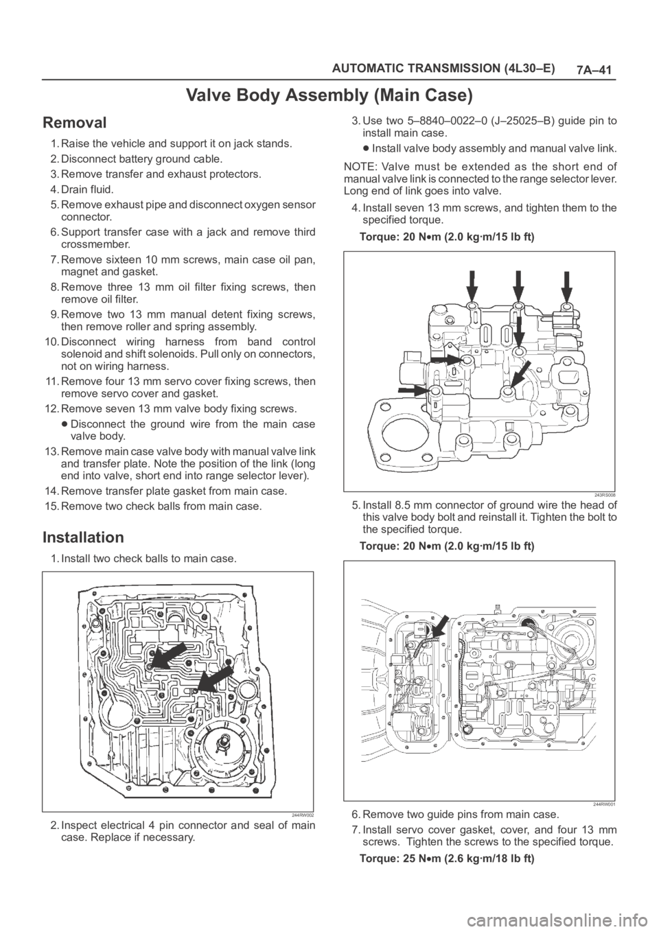
1. Install two check balls to main case.
244RW002
2. Inspect electrical 4 pin connector and seal of main
case. Replace if necessary.3. Use two 5–8840–0022–0 (J–25025–B) guide pin to
install main case.
Install valve body assembly and manual valve link.
NOTE: Valve must be extended as the short end of
manual valve link is connected to the range selector lever.
Long end of link goes into valve.
4. Install seven 13 mm screws, and tighten them to the
specified torque.
To r q u e : 2 0 N
m (2.0 kgꞏm/15 lb ft)
243RS008
5. Install 8.5 mm connector of ground wire the head of
this valve body bolt and reinstall it. Tighten the bolt to
the specified torque.
To r q u e : 2 0 N
m (2.0 kgꞏm/15 lb ft)
244RW001
6. Remove two guide pins from main case.
7. Install servo cover gasket, cover, and four 13 mm
screws. Tighten the screws to the specified torque.
To r q u e : 2 5 N
m (2.6 kgꞏm/18 lb ft)
Page 5732 of 6000
7A–43 AUTOMATIC TRANSMISSION (4L30–E)
Valve Body Assembly (Adapter Case)
Removal
1. Raise the vehicle and support it on jack stands.
2. Disconnect battery ground cable.
3. Drain fluid.
4. Remove transfer and exhaust protectors.
5. Remove exhaust pipe and disconnect oxygen sensor
connector.
6. Remove twelve 10 mm adapter case oil pan fixing
screws, adapter case oil pan, and gasket.
NOTE: Oil pan still contains transmission fluid. Place a
large drain container under the oil pan.
Drain the fluid carefully.
7. Disconnect wiring harness from force motor solenoid
and converter clutch solenoid. Pull only on
connectors, not on wiring harness.
8. Remove seven 13 mm screws from adapter case
valve body assembly, then remove transfer plate, two
gaskets, and adapter case valve body.
Installation
1. Inspect electrical 5 pin connector and seal of adapter
case. Replace if necessary.2. Install gasket, transfer plate, and gasket.
3. Install adapter case valve body and seven 13 mm
screws. Tighten the screws to the specified torque.
To r q u e : 2 0 N
m (2.0 kgꞏm/15 lb ft)
4. Connect wiring harness assembly to converter clutch
solenoid and force motor.
5. Install oil pan gasket, oil pan, and twelve 10 mm
screws. Tighten the screws to the specified torque.
To r q u e : 11 N
m (1.1 kgꞏm/96 lb in)
6. Install exhaust pipe and connect oxygen sensor
connector. Tighten the bolts to the specified torque.
Exhaust pipe flange bolt torque:
43 N
m(4.4kgꞏm/32lbft)
7. Install transfer and exhaust protectors. Tighten the
bolts to the specified torque.
To r q u e : 3 7 N
m(3.8kgꞏm/27lbft)
8. Fill transmission through the overfill screw hole of oil
pan, using ATF DEXRON
–III. Refer to Changing
Transmission Fluid in this section.
9. Connect battery ground cable.
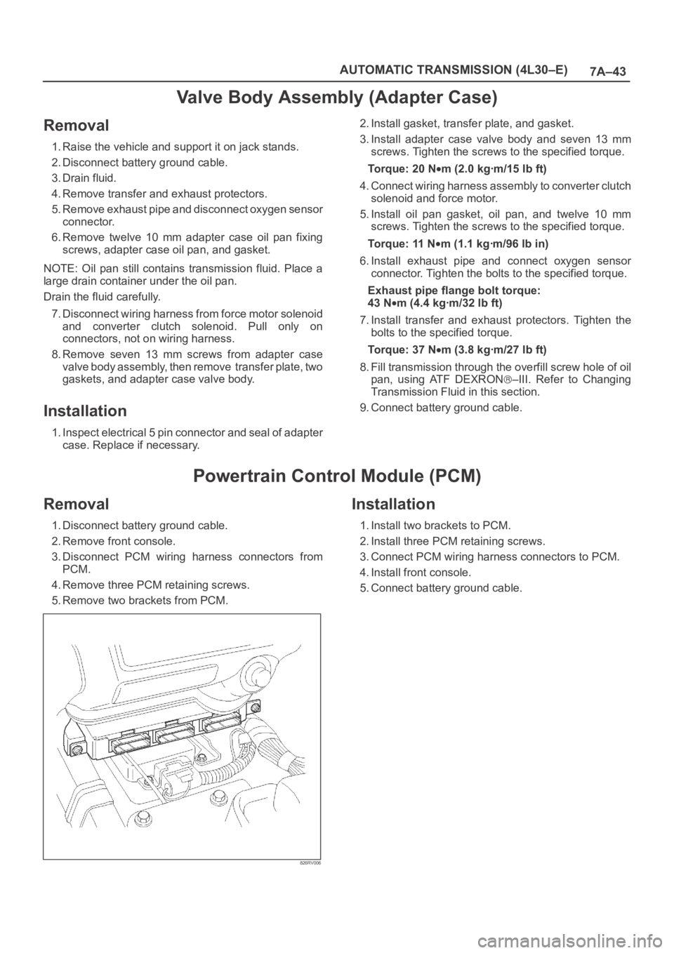
Powertrain Control Module (PCM)
Removal
1. Disconnect battery ground cable.
2. Remove front console.
3. Disconnect PCM wiring harness connectors from
PCM.
4. Remove three PCM retaining screws.
5. Remove two brackets from PCM.
826RV006
Installation
1. Install two brackets to PCM.
2. Install three PCM retaining screws.
3. Connect PCM wiring harness connectors to PCM.
4. Install front console.
5. Connect battery ground cable.
Page 5735 of 6000
7A–46
AUTOMATIC TRANSMISSION (4L30–E)
Rear Oil Seal (Extension Housing)
Removal
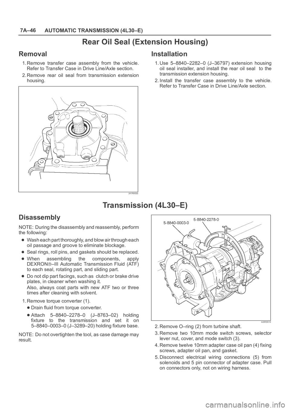
1. Remove transfer case assembly from the vehicle.
Refer to Transfer Case in Drive Line/Axle section.
2. Remove rear oil seal from transmission extension
housing.
241RW005
Installation
1. Use 5–8840–2282–0 (J–36797) extension housing
oil seal installer, and install the rear oil seal to the
transmission extension housing.
2. Install the transfer case assembly to the vehicle.
Refer to Transfer Case in Drive Line/Axle section.
Transmission (4L30–E)
Disassembly
NOTE: During the disassembly and reassembly, perform
the following:
Wash each part thoroughly, and blow air through each
oil passage and groove to eliminate blockage.
Seal rings, roll pins, and gaskets should be replaced.
When assembling the components, apply
DEXRON
–III Automatic Transmission Fluid (ATF)
to each seal, rotating part, and sliding part.
Do not dip part facings, such as clutch or brake drive
plates, in cleaner when washing it.
Also, always coat parts with new ATF two or three
times after cleaning with solvent.
1. Remove torque converter (1).
Drain fluid from torque converter.
Attach 5–8840–2278–0 (J–8763–02) holding
fixture to the transmission and set it on
5–8840–0003–0 (J–3289–20) holding fixture base.
NOTE: Do not overtighten the tool, as case damage may
result.
420RW019
2. Remove O–ring (2) from turbine shaft.
3. Remove two 10mm mode switch screws, selector
lever nut, cover, and mode switch (3).
4. Remove twelve 10mm adapter case oil pan (4) fixing
screws, adapter oil pan, and gasket.
5. Disconnect electrical wiring connections (5) from
solenoids and 5 pin connector of adapter case. Pull
on connectors only, not on wiring harness.
Page 5747 of 6000
7A–58
AUTOMATIC TRANSMISSION (4L30–E)
242RW008
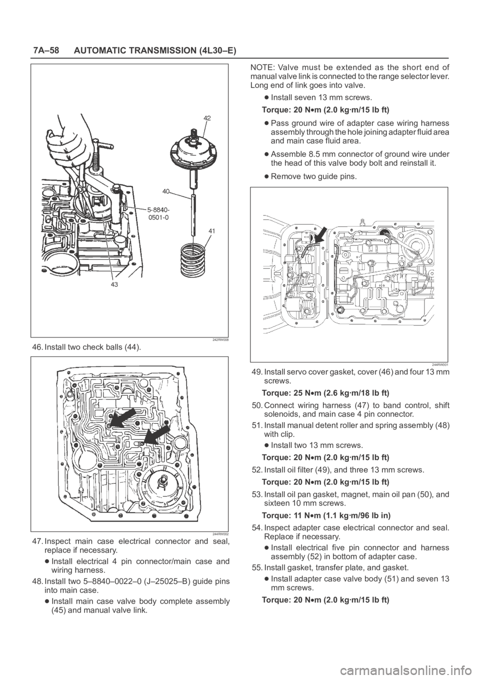
46. Install two check balls (44).
244RW002
47. Inspect main case electrical connector and seal,
replace if necessary.
Install electrical 4 pin connector/main case and
wiring harness.
48. Install two 5–8840–0022–0 (J–25025–B) guide pins
into main case.
Install main case valve body complete assembly
(45) and manual valve link.NOTE: Valve must be extended as the short end of
manual valve link is connected to the range selector lever.
Long end of link goes into valve.
Install seven 13 mm screws.
To r q u e : 2 0 N
m (2.0 kgꞏm/15 lb ft)
Pass ground wire of adapter case wiring harness
assembly through the hole joining adapter fluid area
and main case fluid area.
Assemble 8.5 mm connector of ground wire under
the head of this valve body bolt and reinstall it.
Remove two guide pins.
244RW001
49. Install servo cover gasket, cover (46) and four 13 mm
screws.
To r q u e : 2 5 N
m (2.6 kgꞏm/18 lb ft)
50. Connect wiring harness (47) to band control, shift
solenoids, and main case 4 pin connector.
51. Install manual detent roller and spring assembly (48)
with clip.
Install two 13 mm screws.
To r q u e : 2 0 N
m (2.0 kgꞏm/15 lb ft)
52. Install oil filter (49), and three 13 mm screws.
To r q u e : 2 0 N
m (2.0 kgꞏm/15 lb ft)
53. Install oil pan gasket, magnet, main oil pan (50), and
sixteen 10 mm screws.
To r q u e : 11 N
m (1.1 kgꞏm/96 lb in)
54. Inspect adapter case electrical connector and seal.
Replace if necessary.
Install electrical five pin connector and harness
assembly (52) in bottom of adapter case.
55. Install gasket, transfer plate, and gasket.
Install adapter case valve body (51) and seven 13
mm screws.
Torque: 20 N
m (2.0 kgꞏm/15 lb ft)
Page 5775 of 6000
7A–86
AUTOMATIC TRANSMISSION (4L30–E)
4L30–E Parts List
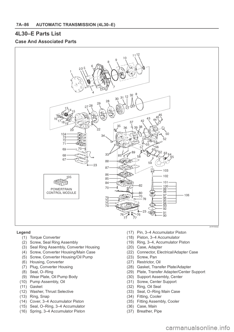
Case And Associated Parts
241RY00022
Legend
(1) Torque Converter
(2) Screw, Seal Ring Assembly
(3) Seal Ring Assembly, Converter Housing
(4) Screw, Converter Housing/Main Case
(5) Screw, Converter Housing/Oil Pump
(6) Housing, Converter
(7) Plug, Converter Housing
(8) Seal, O–Ring
(9) Wear Plate, Oil Pump Body
(10) Pump Assembly, Oil
(11) Gasket
(12) Washer, Thrust Selective
(13) Ring, Snap
(14) Cover, 3–4 Accumulator Piston
(15) Seal, O–Ring, 3–4 Accumulator
(16) Spring, 3–4 Accumulator Piston(17) Pin, 3–4 Accumulator Piston
(18) Piston, 3–4 Accumulator
(19) Ring, 3–4, Accumulator Piston
(20) Case, Adapter
(22) Connector, Electrical/Adapter Case
(23) Screw, Pan
(27) Restrictor, Oil
(28) Gasket, Transfer Plate/Adapter
(29) Plate, Transfer Adapter/Center Support
(30) Support Assembly, Center
(31) Screw, Center Support
(32) Ring, Oil Seal
(33) Seal, O–Ring Main Case
(34) Fitting, Cooler
(35) Fitting Assembly, Cooler
(36) Case, Main
(37) Breather, Pipe