1998 OPEL FRONTERA Electrical
[x] Cancel search: ElectricalPage 1990 of 6000
6E–97 4JX1–TC ENGINE DRIVEABILITY AND EMISSIONS
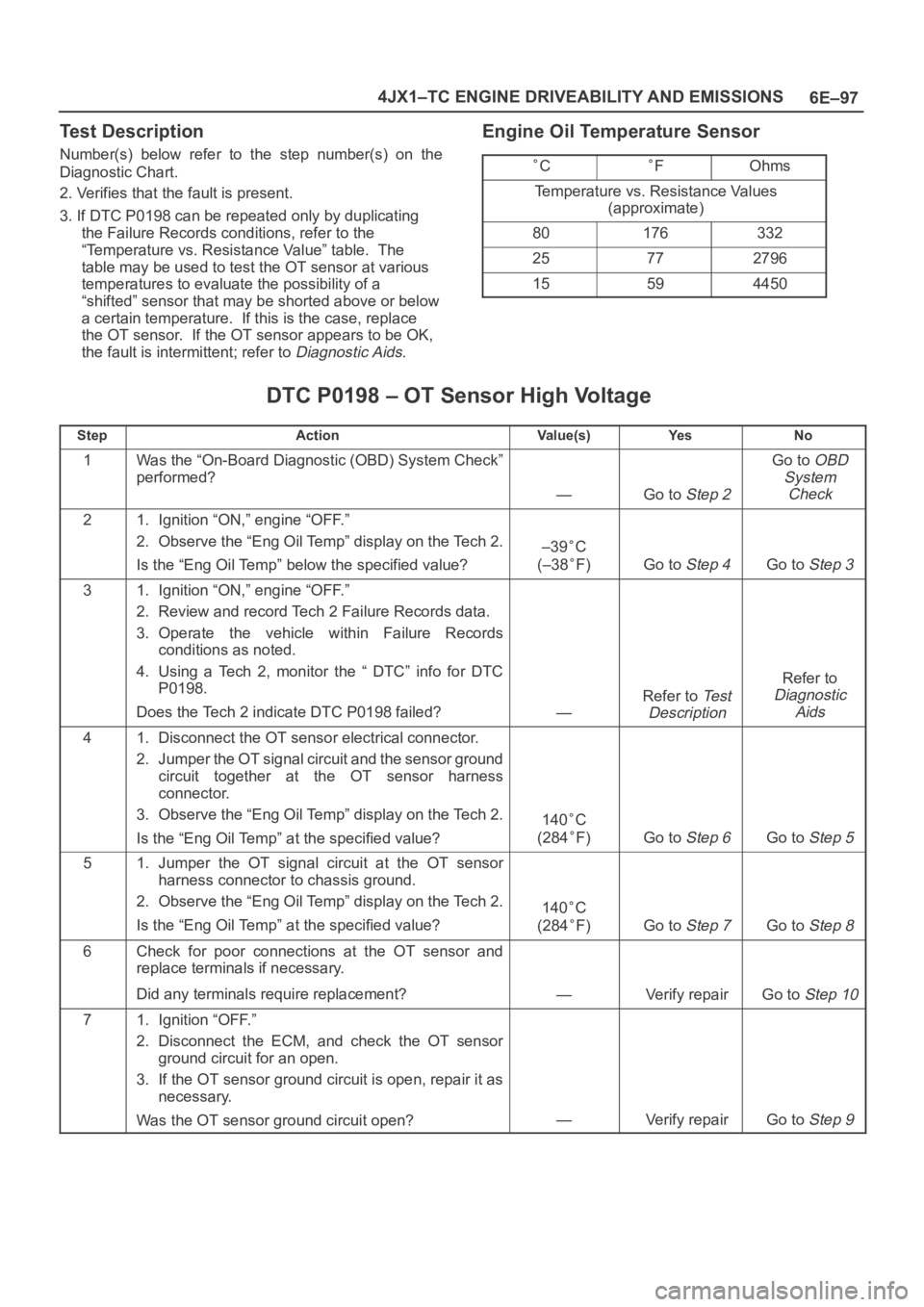
Test Description
Number(s) below refer to the step number(s) on the
Diagnostic Chart.
2. Verifies that the fault is present.
3. If DTC P0198 can be repeated only by duplicating
the Failure Records conditions, refer to the
“Temperature vs. Resistance Value” table. The
table may be used to test the OT sensor at various
temperatures to evaluate the possibility of a
“shifted” sensor that may be shorted above or below
a certain temperature. If this is the case, replace
the OT sensor. If the OT sensor appears to be OK,
the fault is intermittent; refer to
Diagnostic Aids.
Engine Oil Temperature Sensor
CFOhms
Temperature vs. Resistance Values
(approximate)
80176332
25772796
15594450
DTC P0198 – OT Sensor High Voltage
StepActionVa l u e ( s )Ye sNo
1Was the “On-Board Diagnostic (OBD) System Check”
performed?
—Go to Step 2
Go to OBD
System
Check
21. Ignition “ON,” engine “OFF.”
2. Observe the “Eng Oil Temp” display on the Tech 2.
Is the “Eng Oil Temp” below the specified value?
–39C
(–38
F)Go to Step 4Go to Step 3
31. Ignition “ON,” engine “OFF.”
2. Review and record Tech 2 Failure Records data.
3. Operate the vehicle within Failure Records
conditions as noted.
4. Using a Tech 2, monitor the “ DTC” info for DTC
P0198.
Does the Tech 2 indicate DTC P0198 failed?
—
Refer to Te s t
Description
Refer to
Diagnostic
Aids
41. Disconnect the OT sensor electrical connector.
2. Jumper the OT signal circuit and the sensor ground
circuit together at the OT sensor harness
connector.
3. Observe the “Eng Oil Temp” display on the Tech 2.
Is the “Eng Oil Temp” at the specified value?
140C
(284
F)Go to Step 6Go to Step 5
51. Jumper the OT signal circuit at the OT sensor
harness connector to chassis ground.
2. Observe the “Eng Oil Temp” display on the Tech 2.
Is the “Eng Oil Temp” at the specified value?
140C
(284
F)Go to Step 7Go to Step 8
6Check for poor connections at the OT sensor and
replace terminals if necessary.
Did any terminals require replacement?
—Verify repairGo to Step 10
71. Ignition “OFF.”
2. Disconnect the ECM, and check the OT sensor
ground circuit for an open.
3. If the OT sensor ground circuit is open, repair it as
necessary.
Was the OT sensor ground circuit open?
—Verify repairGo to Step 9
Page 2040 of 6000
6E–147 4JX1–TC ENGINE DRIVEABILITY AND EMISSIONS
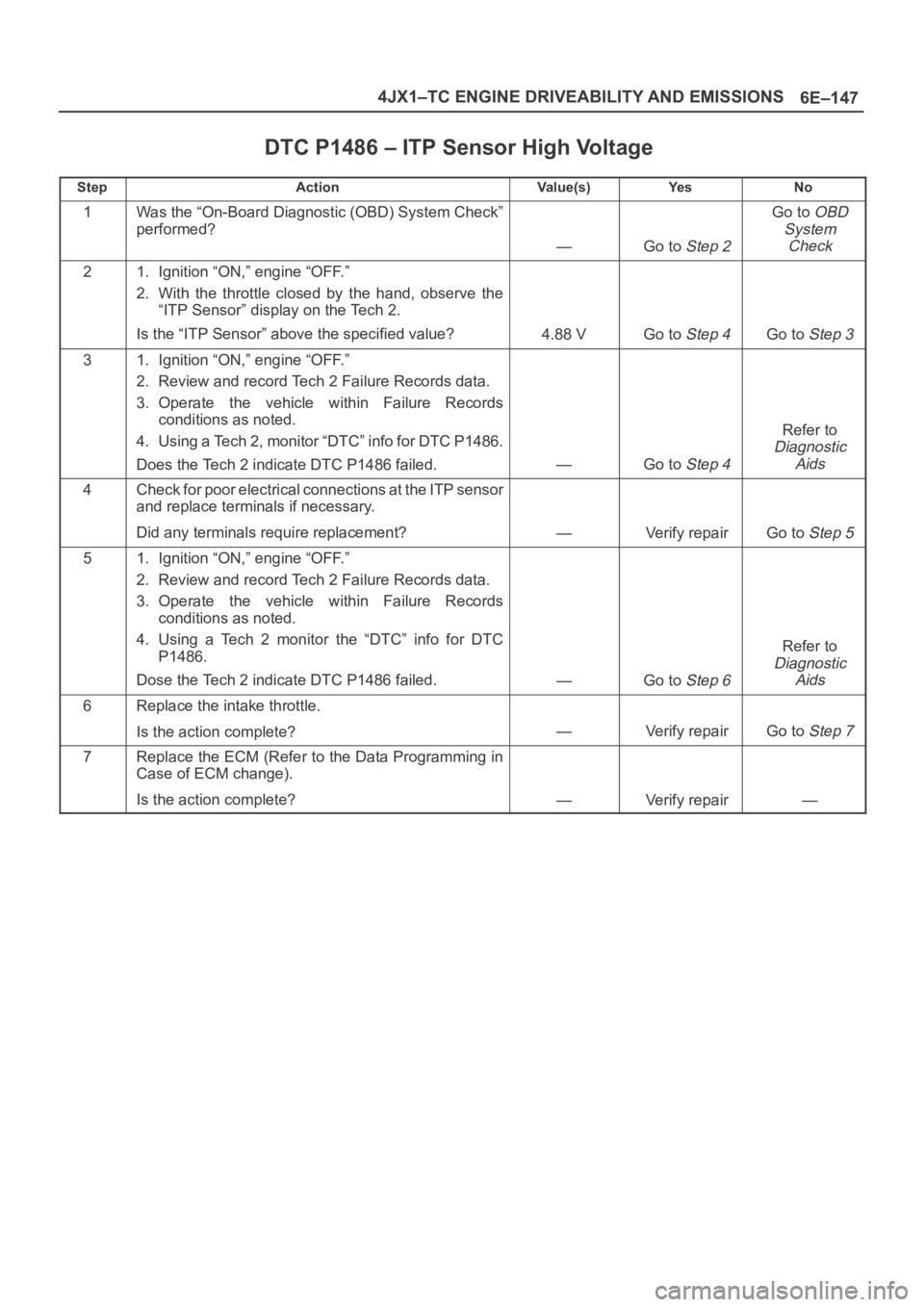
DTC P1486 – ITP Sensor High Voltage
StepActionVa l u e ( s )Ye sNo
1Was the “On-Board Diagnostic (OBD) System Check”
performed?
—Go to Step 2
Go to OBD
System
Check
21. Ignition “ON,” engine “OFF.”
2. With the throttle closed by the hand, observe the
“ITP Sensor” display on the Tech 2.
Is the “ITP Sensor” above the specified value?
4.88 VGo to Step 4Go to Step 3
31. Ignition “ON,” engine “OFF.”
2. Review and record Tech 2 Failure Records data.
3. Operate the vehicle within Failure Records
conditions as noted.
4. Using a Tech 2, monitor “DTC” info for DTC P1486.
Does the Tech 2 indicate DTC P1486 failed.
—Go to Step 4
Refer to
Diagnostic
Aids
4Check for poor electrical connections at the ITP sensor
and replace terminals if necessary.
Did any terminals require replacement?
—Verify repairGo to Step 5
51. Ignition “ON,” engine “OFF.”
2. Review and record Tech 2 Failure Records data.
3. Operate the vehicle within Failure Records
conditions as noted.
4. Using a Tech 2 monitor the “DTC” info for DTC
P1486.
Dose the Tech 2 indicate DTC P1486 failed.
—Go to Step 6
Refer to
Diagnostic
Aids
6Replace the intake throttle.
Is the action complete?
—Verify repairGo to Step 7
7Replace the ECM (Refer to the Data Programming in
Case of ECM change).
Is the action complete?
—Verify repair—
Page 2052 of 6000
6E–159 4JX1–TC ENGINE DRIVEABILITY AND EMISSIONS
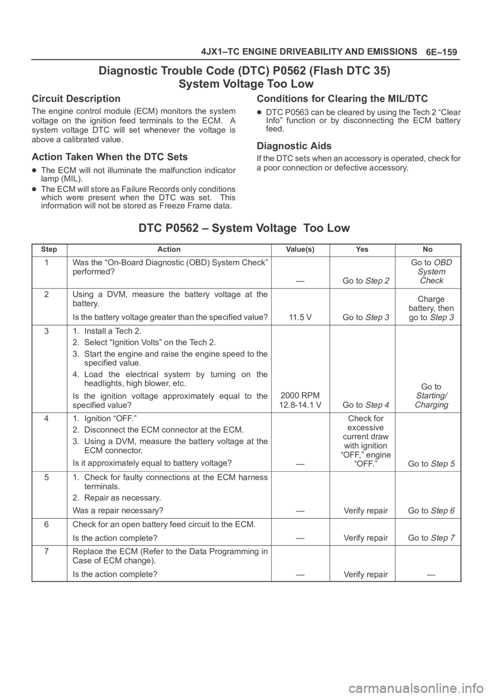
Diagnostic Trouble Code (DTC) P0562 (Flash DTC 35)
System Voltage Too Low
Circuit Description
The engine control module (ECM) monitors the system
voltage on the ignition feed terminals to the ECM. A
system voltage DTC will set whenever the voltage is
above a calibrated value.
Action Taken When the DTC Sets
The ECM will not illuminate the malfunction indicator
lamp (MIL).
The ECM will store as Failure Records only conditions
which were present when the DTC was set. This
information will not be stored as Freeze Frame data.
Conditions for Clearing the MIL/DTC
DTC P0563 can be cleared by using the Tech 2 “Clear
Info” function or by disconnecting the ECM battery
feed.
Diagnostic Aids
If the DTC sets when an accessory is operated, check for
a poor connection or defective accessory.
DTC P0562 – System Voltage Too Low
StepActionVa l u e ( s )Ye sNo
1Was the “On-Board Diagnostic (OBD) System Check”
performed?
—Go to Step 2
Go to OBD
System
Check
2Using a DVM, measure the battery voltage at the
battery.
Is the battery voltage greater than the specified value?
11.5 VGo to Step 3
Charge
battery, then
go to
Step 3
31. Install a Tech 2.
2. Select “Ignition Volts” on the Tech 2.
3. Start the engine and raise the engine speed to the
specified value.
4. Load the electrical system by turning on the
headlights, high blower, etc.
Is the ignition voltage approximately equal to the
specified value?
2000 RPM
12.8-14.1 V
Go to Step 4
Go to
Starting/
Charging
41. Ignition “OFF.”
2. Disconnect the ECM connector at the ECM.
3. Using a DVM, measure the battery voltage at the
ECM connector.
Is it approximately equal to battery voltage?
—
Check for
excessive
current draw
with ignition
“OFF,” engine
“OFF.”
Go to Step 5
51. Check for faulty connections at the ECM harness
terminals.
2. Repair as necessary.
Was a repair necessary?
—Verify repairGo to Step 6
6Check for an open battery feed circuit to the ECM.
Is the action complete?
—Verify repairGo to Step 7
7Replace the ECM (Refer to the Data Programming in
Case of ECM change).
Is the action complete?
—Verify repair—
Page 2069 of 6000
6E–176
4JX1–TC ENGINE DRIVEABILITY AND EMISSIONS
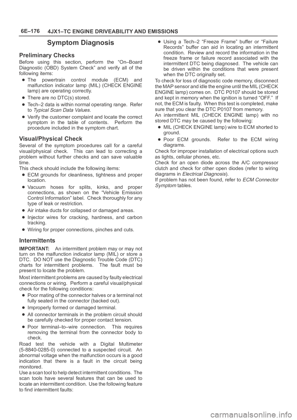
Symptom Diagnosis
Preliminary Checks
Before using this section, perform the “On–Board
Diagnostic (OBD) System Check” and verify all of the
following items:
The powertrain control module (ECM) and
malfunction indicator lamp (MIL) (CHECK ENGINE
lamp) are operating correctly.
There are no DTC(s) stored.
Tech–2 data is within normal operating range. Refer
to
Typical Scan Data Values.
Verify the customer complaint and locate the correct
symptom in the table of contents. Perform the
procedure included in the symptom chart.
Visual/Physical Check
Several of the symptom procedures call for a careful
visual/physical check. This can lead to correcting a
problem without further checks and can save valuable
time.
This check should include the following items:
ECM grounds for cleanliness, tightness and proper
location.
Vacuum hoses for splits, kinks, and proper
connections, as shown on the “Vehicle Emission
Control Information” label. Check thoroughly for any
type of leak or restriction.
Air intake ducts for collapsed or damaged areas.
Injector wires for cracking, hardness, and carbon
tracking.
Wiring for proper connections, pinches and cuts.
Intermittents
IMPORTANT:An intermittent problem may or may not
turn on the malfunction indicator lamp (MIL) or store a
DTC. DO NOT use the Diagnostic Trouble Code (DTC)
charts for intermittent problems. The fault must be
present to locate the problem.
Most intermittent problems are caused by faulty electrical
connections or wiring. Perform a careful visual/physical
check for the following conditions:
Poor mating of the connector halves or a terminal not
fully seated in the connector (backed out).
Improperly formed or damaged terminal.
All connector terminals in the problem circuit should
be carefully checked for proper contact tension.
Poor terminal–to–wire connection. This requires
removing the terminal from the connector body to
check.
Road test the vehicle with a Digital Multimeter
(5-8840-0285-0) connected to a suspected circuit. An
abnormal voltage when the malfunction occurs is a good
indication that there is a fault in the circuit being
monitored.
Use a scan tool to help detect intermittent conditions. The
scan tools have several features that can be used to
locate an intermittent condition. Use the following feature
to find intermittent faults:
Using a Tech–2 “Freeze Frame” buffer or “Failure
Records” buffer can aid in locating an intermittent
condition. Review and record the information in the
freeze frame or failure record associated with the
intermittent DTC being diagnosed. The vehicle can
be driven within the conditions that were present
when the DTC originally set.
To check for loss of diagnostic code memory, disconnect
the MAP sensor and idle the engine until the MIL (CHECK
ENGINE lamp) comes on. DTC P0107 should be stored
and kept in memory when the ignition is turned “OFF.” If
not, the ECM is faulty. When this test is completed, make
sure that you clear the DTC P0107 from memory.
An intermittent MIL (CHECK ENGINE lamp) with no
stored DTC may be caused by the following:
MIL (CHECK ENGINE lamp) wire to ECM shorted to
ground.
Poor ECM grounds. Refer to the ECM wiring
diagrams.
Check for improper installation of electrical options such
as lights, cellular phones, etc.
Check for an open diode across the A/C compressor
clutch and check for other open diodes (refer to wiring
diagrams in
Electrical Diagnosis).
If problem has not been found, refer to
ECM Connector
Symptom
tables.
Page 2071 of 6000
6E–178
4JX1–TC ENGINE DRIVEABILITY AND EMISSIONS
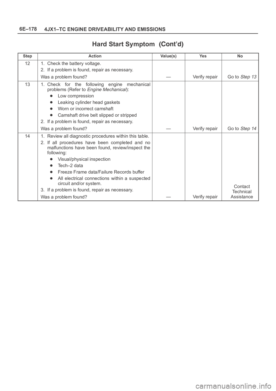
Hard Start Symptom
StepNo Ye s Va l u e ( s ) Action
121. Check the battery voltage.
2. If a problem is found, repair as necessary.
Was a problem found?
—Verify repairGo to Step 13
131. Check for the following engine mechanical
problems (Refer to
Engine Mechanical):
Low compression
Leaking cylinder head gaskets
Worn or incorrect camshaft
Camshaft drive belt slipped or stripped
2. If a problem is found, repair as necessary.
Was a problem found?
—Verify repairGo to Step 14
141. Review all diagnostic procedures within this table.
2. If all procedures have been completed and no
malfunctions have been found, review/inspect the
following:
Visual/physical inspection
Tech–2 data
Freeze Frame data/Failure Records buffer
All electrical connections within a suspected
circuit and/or system.
3. If a problem is found, repair as necessary.
Was a problem found?
—Verify repair
Contact
Te c h n i c a l
Assistance
Page 2072 of 6000
6E–179 4JX1–TC ENGINE DRIVEABILITY AND EMISSIONS
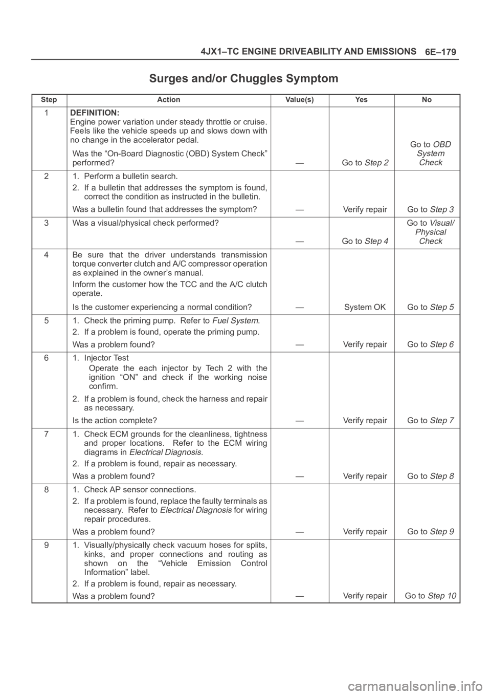
Surges and/or Chuggles Symptom
StepActionVa l u e ( s )Ye sNo
1DEFINITION:
Engine power variation under steady throttle or cruise.
Feels like the vehicle speeds up and slows down with
no change in the accelerator pedal.
Was the “On-Board Diagnostic (OBD) System Check”
performed?
—Go to Step 2
Go to OBD
System
Check
21. Perform a bulletin search.
2. If a bulletin that addresses the symptom is found,
correct the condition as instructed in the bulletin.
Was a bulletin found that addresses the symptom?
—Verify repairGo to Step 3
3Was a visual/physical check performed?
—Go to Step 4
Go to Visual/
Physical
Check
4Be sure that the driver understands transmission
torque converter clutch and A/C compressor operation
as explained in the owner’s manual.
Inform the customer how the TCC and the A/C clutch
operate.
Is the customer experiencing a normal condition?
—System OKGo to Step 5
51. Check the priming pump. Refer to Fuel System.
2. If a problem is found, operate the priming pump.
Was a problem found?
—Verify repairGo to Step 6
61. Injector Test
Operate the each injector by Tech 2 with the
ignition “ON” and check if the working noise
confirm.
2. If a problem is found, check the harness and repair
as necessary.
Is the action complete?
—Verify repairGo to Step 7
71. Check ECM grounds for the cleanliness, tightness
and proper locations. Refer to the ECM wiring
diagrams in
Electrical Diagnosis.
2. If a problem is found, repair as necessary.
Was a problem found?
—Verify repairGo to Step 8
81. Check AP sensor connections.
2. If a problem is found, replace the faulty terminals as
necessary. Refer to
Electrical Diagnosis for wiring
repair procedures.
Was a problem found?
—Verify repairGo to Step 9
91. Visually/physically check vacuum hoses for splits,
kinks, and proper connections and routing as
shown on the “Vehicle Emission Control
Information” label.
2. If a problem is found, repair as necessary.
Was a problem found?
—Verify repairGo to Step 10
Page 2073 of 6000
6E–180
4JX1–TC ENGINE DRIVEABILITY AND EMISSIONS
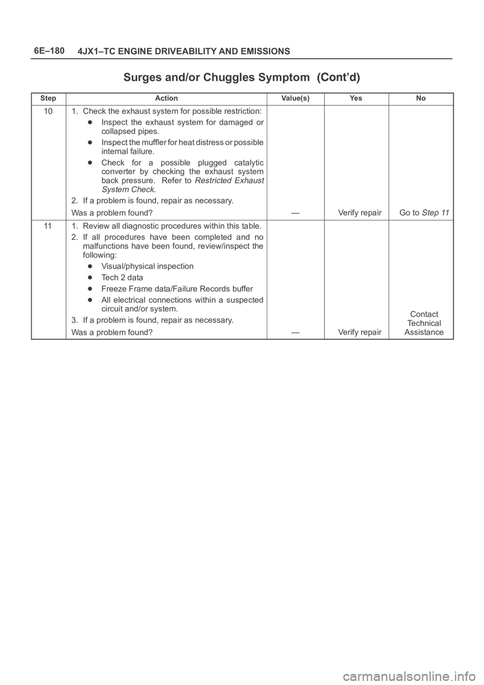
Surges and/or Chuggles Symptom
StepNo Ye s Va l u e ( s ) Action
101. Check the exhaust system for possible restriction:
Inspect the exhaust system for damaged or
collapsed pipes.
Inspect the muffler for heat distress or possible
internal failure.
Check for a possible plugged catalytic
converter by checking the exhaust system
back pressure. Refer to
Restricted Exhaust
System Check
.
2. If a problem is found, repair as necessary.
Was a problem found?
—Verify repairGo to Step 11
111. Review all diagnostic procedures within this table.
2. If all procedures have been completed and no
malfunctions have been found, review/inspect the
following:
Visual/physical inspection
Te c h 2 d a t a
Freeze Frame data/Failure Records buffer
All electrical connections within a suspected
circuit and/or system.
3. If a problem is found, repair as necessary.
Was a problem found?
—Verify repair
Contact
Te c h n i c a l
Assistance
Page 2074 of 6000
6E–181 4JX1–TC ENGINE DRIVEABILITY AND EMISSIONS
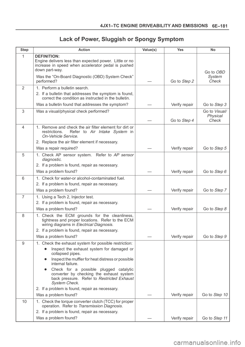
Lack of Power, Sluggish or Spongy Symptom
StepActionVa l u e ( s )Ye sNo
1DEFINITION:
Engine delivers less than expected power. Little or no
increase in speed when accelerator pedal is pushed
down part-way.
Was the “On-Board Diagnostic (OBD) System Check”
performed?
—Go to Step 2
Go to OBD
System
Check
21. Perform a bulletin search.
2. If a bulletin that addresses the symptom is found,
correct the condition as instructed in the bulletin.
Was a bulletin found that addresses the symptom?
—Verify repairGo to Step 3
3Was a visual/physical check performed?
—Go to Step 4
Go to Visual/
Physical
Check
41. Remove and check the air filter element for dirt or
restrictions. Refer to
Air Intake System in
On-Vehicle Service.
2. Replace the air filter element if necessary.
Was a repair required?
—Verify repairGo to Step 5
51. Check AP sensor system. Refer to AP sensor
diagnostic
.
2. If a problem is found, repair as necessary.
Was a problem found?
—Verify repairGo to Step 6
61. Check for water-or alcohol-contaminated fuel.
2. If a problem is found, repair as necessary.
Was a problem found?
—Verify repairGo to Step 7
71. Using a Tech 2, Injector test.
2. If a problem is found, repair as necessary.
Was a problem found?
—Verify repairGo to Step 8
81. Check the ECM grounds for the cleanliness,
tightness and proper locations. Refer to the ECM
wiring diagrams in
Electrical Diagnosis.
2. If a problem is found, repair as necessary.
Was a problem found?
—Verify repairGo to Step 9
91. Check the exhaust system for possible restriction:
Inspect the exhaust system for damaged or
collapsed pipes.
Inspect the muffler for heat distress or possible
internal failure.
Check for a possible plugged catalytic
converter by checking the exhaust system
back pressure. Refer to
Restricted Exhaust
System Check
.
2. If a problem is found, repair as necessary.
Was a problem found?
—Verify repairGo to Step 10
101. Check the torque converter clutch (TCC) for proper
operation. Refer to
Transmission Diagnosis.
2. If a problem is found, repair as necessary.
Was a problem found?
—Verify repairGo to Step 11