1998 OPEL FRONTERA rack
[x] Cancel search: rackPage 1400 of 6000
6E–283 ENGINE DRIVEABILITY AND EMISSIONS
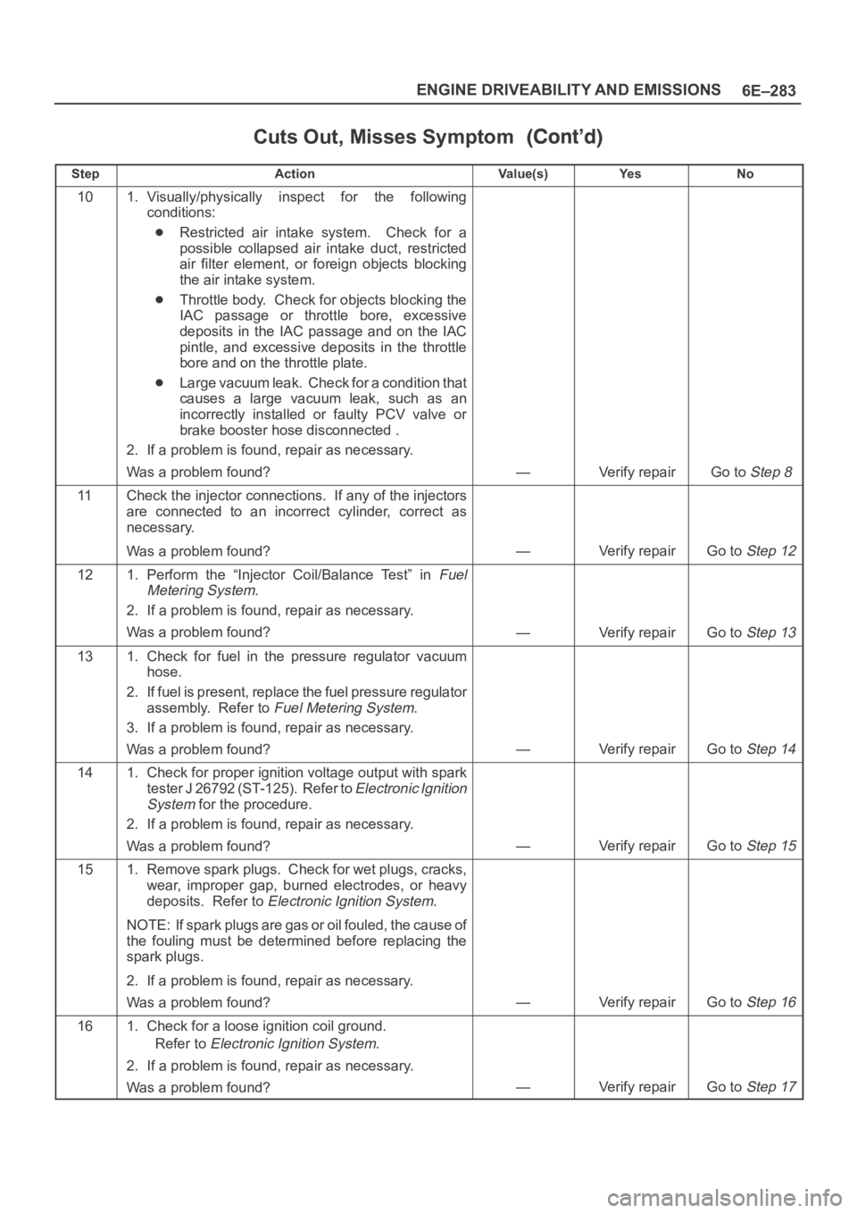
Cuts Out, Misses Symptom
StepNo Ye s Va l u e ( s ) Action
101. Visually/physically inspect for the following
conditions:
Restricted air intake system. Check for a
possible collapsed air intake duct, restricted
air filter element, or foreign objects blocking
the air intake system.
Throttle body. Check for objects blocking the
IAC passage or throttle bore, excessive
deposits in the IAC passage and on the IAC
pintle, and excessive deposits in the throttle
bore and on the throttle plate.
Large vacuum leak. Check for a condition that
causes a large vacuum leak, such as an
incorrectly installed or faulty PCV valve or
brake booster hose disconnected .
2. If a problem is found, repair as necessary.
Was a problem found?
—Verify repairGo to Step 8
11Check the injector connections. If any of the injectors
are connected to an incorrect cylinder, correct as
necessary.
Was a problem found?
—Verify repairGo to Step 12
121. Perform the “Injector Coil/Balance Test” in Fuel
Metering System
.
2. If a problem is found, repair as necessary.
Was a problem found?
—Verify repairGo to Step 13
131. Check for fuel in the pressure regulator vacuum
hose.
2. If fuel is present, replace the fuel pressure regulator
assembly. Refer to
Fuel Metering System.
3. If a problem is found, repair as necessary.
Was a problem found?
—Verify repairGo to Step 14
141. Check for proper ignition voltage output with spark
tester J 26792 (ST-125). Refer to
Electronic Ignition
System
for the procedure.
2. If a problem is found, repair as necessary.
Was a problem found?
—Verify repairGo to Step 15
151. Remove spark plugs. Check for wet plugs, cracks,
wear, improper gap, burned electrodes, or heavy
deposits. Refer to
Electronic Ignition System.
NOTE: If spark plugs are gas or oil fouled, the cause of
the fouling must be determined before replacing the
spark plugs.
2. If a problem is found, repair as necessary.
Was a problem found?
—Verify repairGo to Step 16
161. Check for a loose ignition coil ground.
Refer to
Electronic Ignition System.
2. If a problem is found, repair as necessary.
Was a problem found?
—Verify repairGo to Step 17
Page 1401 of 6000
6E–284
ENGINE DRIVEABILITY AND EMISSIONS
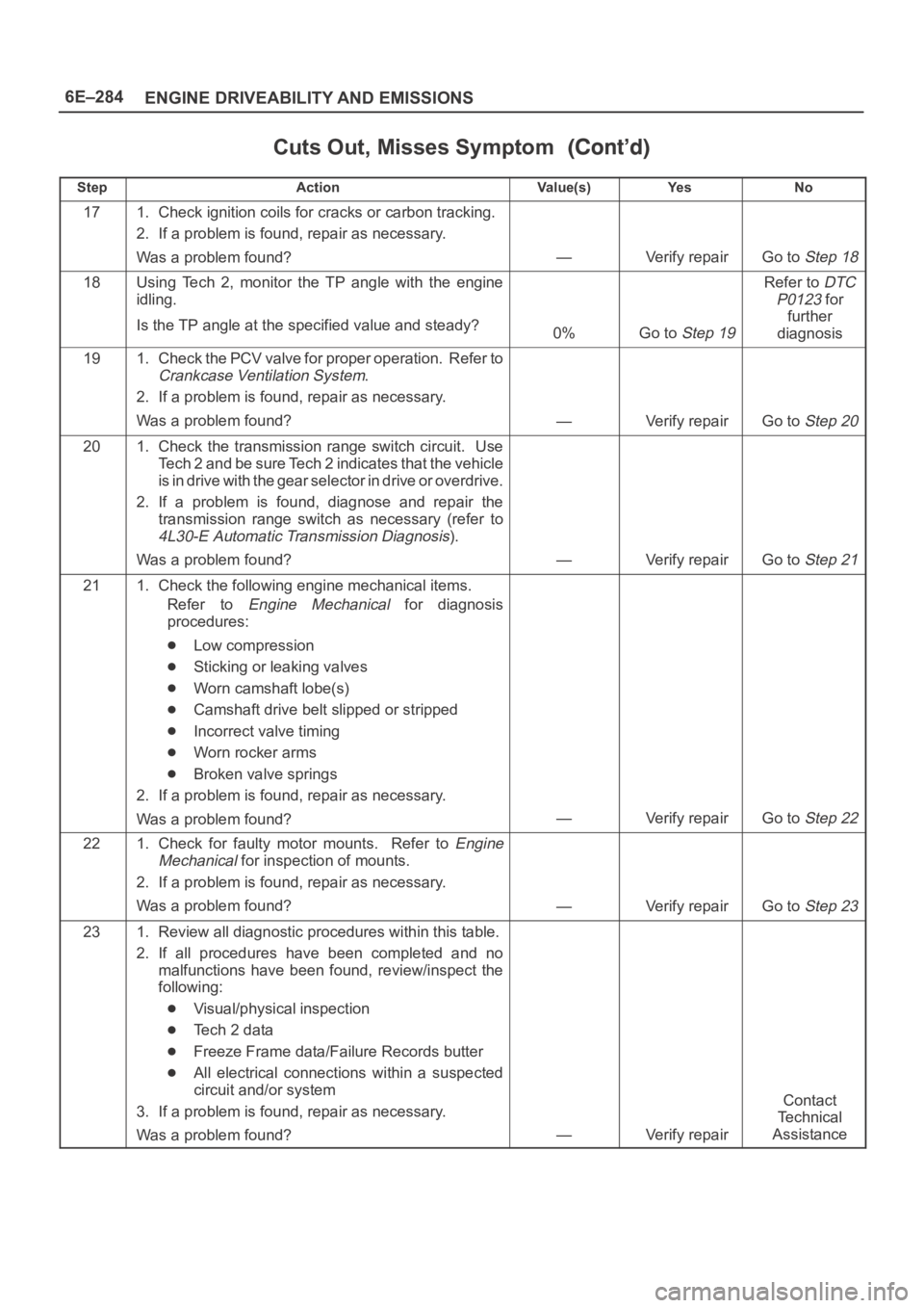
Cuts Out, Misses Symptom
StepNo Ye s Va l u e ( s ) Action
171. Check ignition coils for cracks or carbon tracking.
2. If a problem is found, repair as necessary.
Was a problem found?
—Verify repairGo to Step 18
18Using Tech 2, monitor the TP angle with the engine
idling.
Is the TP angle at the specified value and steady?
0%Go to Step 19
Refer to DTC
P0123
for
further
diagnosis
191. Check the PCV valve for proper operation. Refer to
Crankcase Ventilation System.
2. If a problem is found, repair as necessary.
Was a problem found?
—Verify repairGo to Step 20
201. Check the transmission range switch circuit. Use
Tech 2 and be sure Tech 2 indicates that the vehicle
is in drive with the gear selector in drive or overdrive.
2. If a problem is found, diagnose and repair the
transmission range switch as necessary (refer to
4L30-E Automatic Transmission Diagnosis).
Was a problem found?
—Verify repairGo to Step 21
211. Check the following engine mechanical items.
Refer to
Engine Mechanical for diagnosis
procedures:
Low compression
Sticking or leaking valves
Worn camshaft lobe(s)
Camshaft drive belt slipped or stripped
Incorrect valve timing
Worn rocker arms
Broken valve springs
2. If a problem is found, repair as necessary.
Was a problem found?
—Verify repairGo to Step 22
221. Check for faulty motor mounts. Refer to Engine
Mechanical
for inspection of mounts.
2. If a problem is found, repair as necessary.
Was a problem found?
—Verify repairGo to Step 23
231. Review all diagnostic procedures within this table.
2. If all procedures have been completed and no
malfunctions have been found, review/inspect the
following:
Visual/physical inspection
Te c h 2 d a t a
Freeze Frame data/Failure Records butter
All electrical connections within a suspected
circuit and/or system
3. If a problem is found, repair as necessary.
Was a problem found?
—Verify repair
Contact
Te c h n i c a l
Assistance
Page 1403 of 6000
6E–286
ENGINE DRIVEABILITY AND EMISSIONS
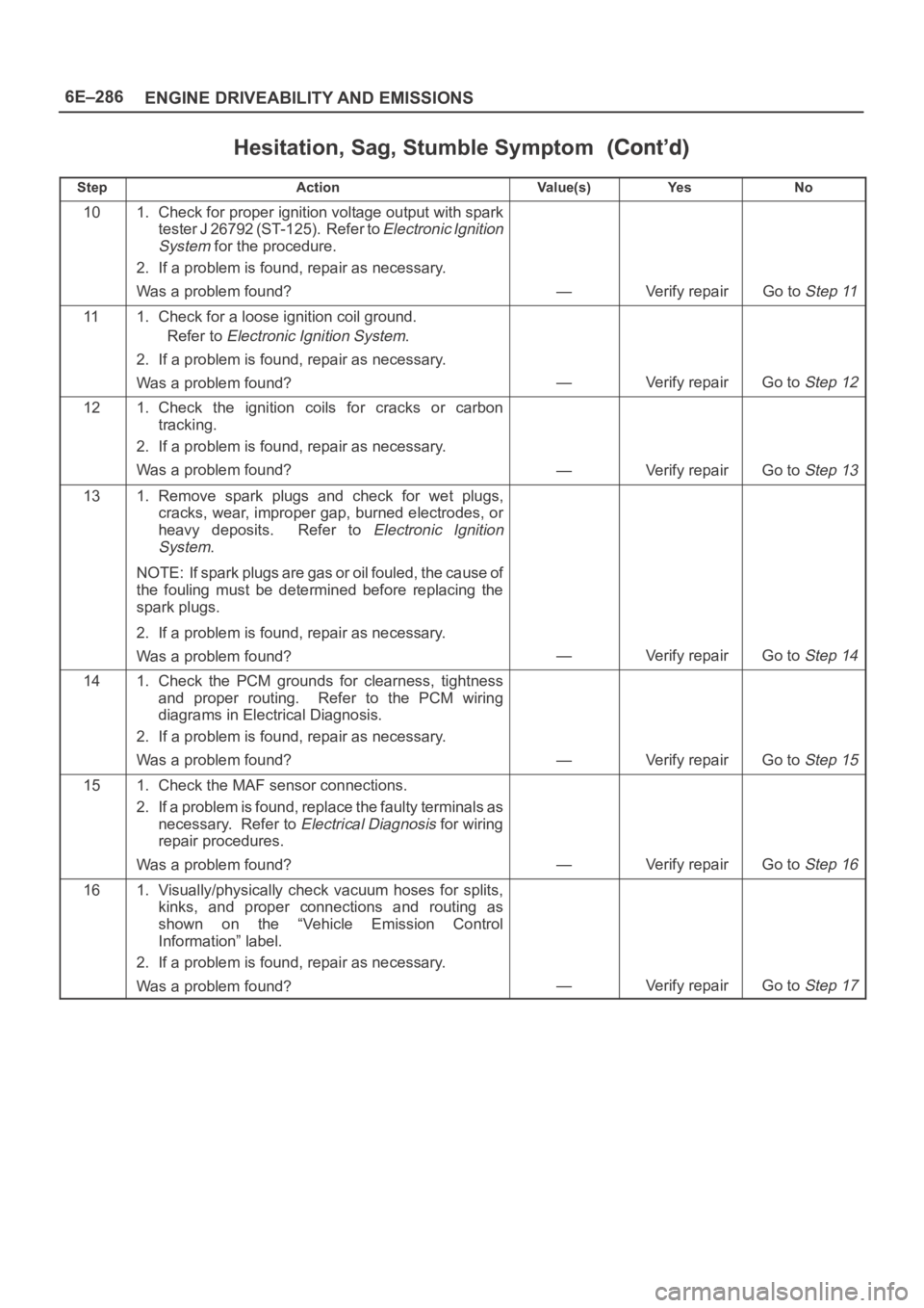
Hesitation, Sag, Stumble Symptom
StepNo Ye s Va l u e ( s ) Action
101. Check for proper ignition voltage output with spark
tester J 26792 (ST-125). Refer to
Electronic Ignition
System
for the procedure.
2. If a problem is found, repair as necessary.
Was a problem found?
—Verify repairGo to Step 11
111. Check for a loose ignition coil ground.
Refer to
Electronic Ignition System.
2. If a problem is found, repair as necessary.
Was a problem found?
—Verify repairGo to Step 12
121. Check the ignition coils for cracks or carbon
tracking.
2. If a problem is found, repair as necessary.
Was a problem found?
—Verify repairGo to Step 13
131. Remove spark plugs and check for wet plugs,
cracks, wear, improper gap, burned electrodes, or
heavy deposits. Refer to
Electronic Ignition
System
.
NOTE: If spark plugs are gas or oil fouled, the cause of
the fouling must be determined before replacing the
spark plugs.
2. If a problem is found, repair as necessary.
Was a problem found?
—Verify repairGo to Step 14
141. Check the PCM grounds for clearness, tightness
and proper routing. Refer to the PCM wiring
diagrams in Electrical Diagnosis.
2. If a problem is found, repair as necessary.
Was a problem found?
—Verify repairGo to Step 15
151. Check the MAF sensor connections.
2. If a problem is found, replace the faulty terminals as
necessary. Refer to
Electrical Diagnosis for wiring
repair procedures.
Was a problem found?
—Verify repairGo to Step 16
161. Visually/physically check vacuum hoses for splits,
kinks, and proper connections and routing as
shown on the “Vehicle Emission Control
Information” label.
2. If a problem is found, repair as necessary.
Was a problem found?
—Verify repairGo to Step 17
Page 1408 of 6000
6E–291 ENGINE DRIVEABILITY AND EMISSIONS
Camshaft Position (CMP)
Sensor
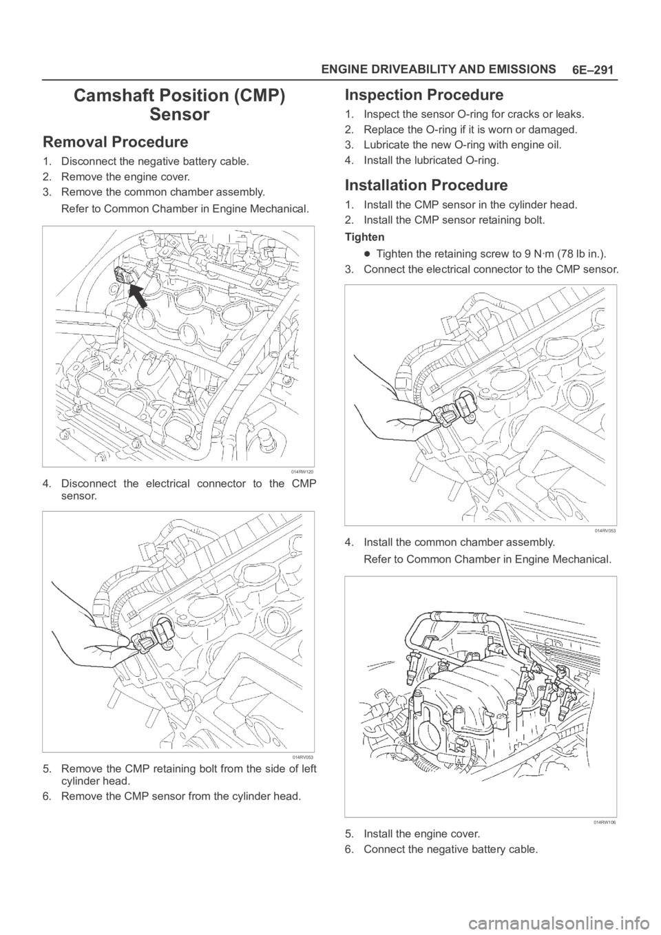
Removal Procedure
1. Disconnect the negative battery cable.
2. Remove the engine cover.
3. Remove the common chamber assembly.
Refer to Common Chamber in Engine Mechanical.
014RW120
4. Disconnect the electrical connector to the CMP
sensor.
014RV053
5. Remove the CMP retaining bolt from the side of left
cylinder head.
6. Remove the CMP sensor from the cylinder head.
Inspection Procedure
1. Inspect the sensor O-ring for cracks or leaks.
2. Replace the O-ring if it is worn or damaged.
3. Lubricate the new O-ring with engine oil.
4. Install the lubricated O-ring.
Installation Procedure
1. Install the CMP sensor in the cylinder head.
2. Install the CMP sensor retaining bolt.
Tighten
Tighten the retaining screw to 9 Nꞏm (78 lb in.).
3. Connect the electrical connector to the CMP sensor.
014RV053
4. Install the common chamber assembly.
Refer to Common Chamber in Engine Mechanical.
014RW106
5. Install the engine cover.
6. Connect the negative battery cable.
Page 1409 of 6000
6E–292
ENGINE DRIVEABILITY AND EMISSIONS
Crankshaft Position (CKP)
Sensor
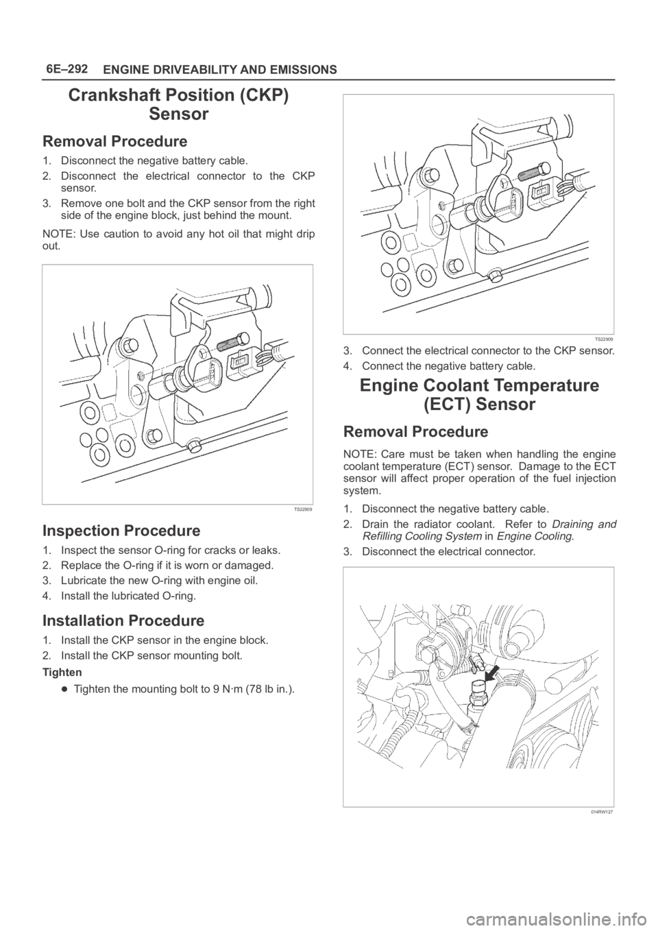
Removal Procedure
1. Disconnect the negative battery cable.
2. Disconnect the electrical connector to the CKP
sensor.
3. Remove one bolt and the CKP sensor from the right
side of the engine block, just behind the mount.
NOTE: Use caution to avoid any hot oil that might drip
out.
TS22909
Inspection Procedure
1. Inspect the sensor O-ring for cracks or leaks.
2. Replace the O-ring if it is worn or damaged.
3. Lubricate the new O-ring with engine oil.
4. Install the lubricated O-ring.
Installation Procedure
1. Install the CKP sensor in the engine block.
2. Install the CKP sensor mounting bolt.
Tighten
Tighten the mounting bolt to 9 Nꞏm (78 lb in.).
TS22909
3. Connect the electrical connector to the CKP sensor.
4. Connect the negative battery cable.
Engine Coolant Temperature
(ECT) Sensor
Removal Procedure
NOTE: Care must be taken when handling the engine
coolant temperature (ECT) sensor. Damage to the ECT
sensor will affect proper operation of the fuel injection
system.
1. Disconnect the negative battery cable.
2. Drain the radiator coolant. Refer to
Draining and
Refilling Cooling System
in Engine Cooling.
3. Disconnect the electrical connector.
014RW127
Page 1414 of 6000
6E–297 ENGINE DRIVEABILITY AND EMISSIONS
Mass Air Flow (MAF) Sensor
Removal Procedure
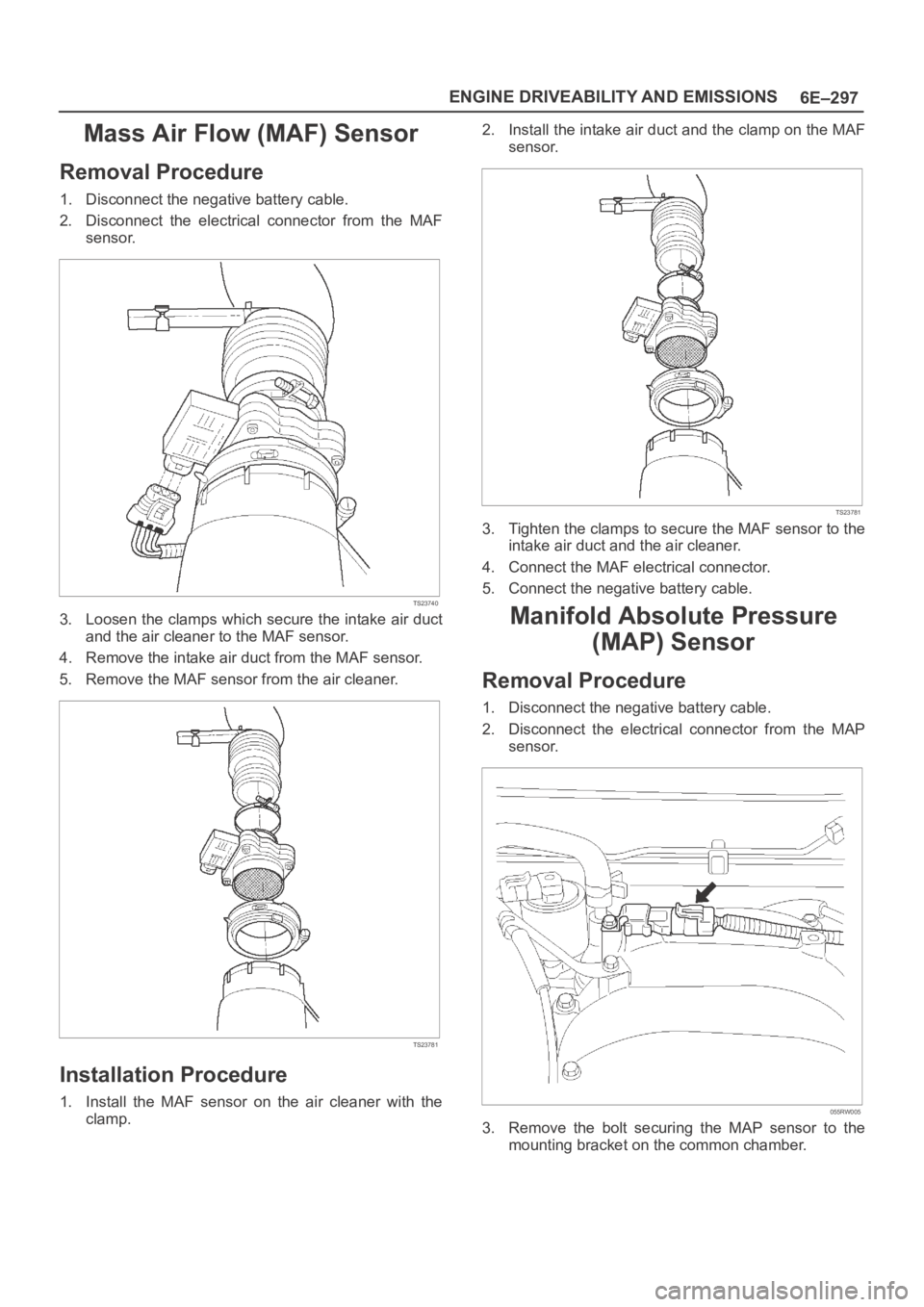
1. Disconnect the negative battery cable.
2. Disconnect the electrical connector from the MAF
sensor.
TS23740
3. Loosen the clamps which secure the intake air duct
and the air cleaner to the MAF sensor.
4. Remove the intake air duct from the MAF sensor.
5. Remove the MAF sensor from the air cleaner.
TS23781
Installation Procedure
1. Install the MAF sensor on the air cleaner with the
clamp.2. Install the intake air duct and the clamp on the MAF
sensor.
TS23781
3. Tighten the clamps to secure the MAF sensor to the
intake air duct and the air cleaner.
4. Connect the MAF electrical connector.
5. Connect the negative battery cable.
Manifold Absolute Pressure
(MAP) Sensor
Removal Procedure
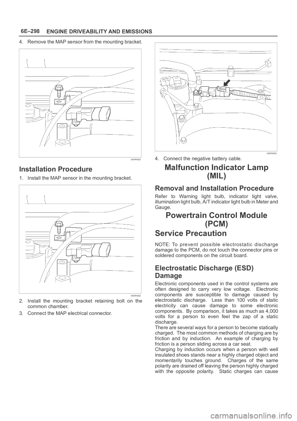
1. Disconnect the negative battery cable.
2. Disconnect the electrical connector from the MAP
sensor.
055RW005
3. Remove the bolt securing the MAP sensor to the
mounting bracket on the common chamber.
Page 1415 of 6000
6E–298
ENGINE DRIVEABILITY AND EMISSIONS
4. Remove the MAP sensor from the mounting bracket.
055RW002
Installation Procedure
1. Install the MAP sensor in the mounting bracket.
055RW002
2. Install the mounting bracket retaining bolt on the
common chamber.
3. Connect the MAP electrical connector.
055RW005
4. Connect the negative battery cable.
Malfunction Indicator Lamp
(MIL)
Removal and Installation Procedure
Refer to Warning light bulb, indicator light valve,
illumination light bulb, A/T indicator light bulb in Meter and
Gauge.
Powertrain Control Module
(PCM)
Service Precaution
NOTE: To prevent possible electrostatic discharge
damage to the PCM, do not touch the connector pins or
soldered components on the circuit board.
Electrostatic Discharge (ESD)
Damage
Electronic components used in the control systems are
often designed to carry very low voltage. Electronic
components are susceptible to damage caused by
electrostatic discharge. Less than 100 volts of static
electricity can cause damage to some electronic
components. By comparison, it takes as much as 4,000
volts for a person to even feel the zap of a static
discharge.
There are several ways for a person to become statically
charged. The most common methods of charging are by
friction and by induction. An example of charging by
friction is a person sliding across a car seat.
Charging by induction occurs when a person with well
insulated shoes stands near a highly charged object and
momentarily touches ground. Charges of the same
polarity are drained off leaving the person highly charged
with the opposite polarity. Static charges can cause
Page 1421 of 6000
6E–304
ENGINE DRIVEABILITY AND EMISSIONS
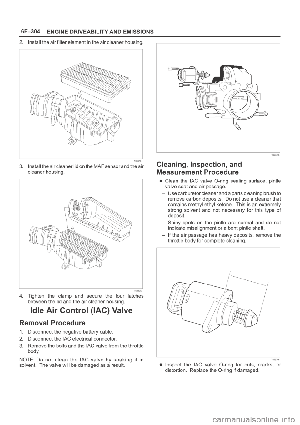
2. Install the air filter element in the air cleaner housing.
TS23794
3. Install the air cleaner lid on the MAF sensor and the air
cleaner housing.
TS23973
4. Tighten the clamp and secure the four latches
between the lid and the air cleaner housing.
Idle Air Control (IAC) Valve
Removal Procedure
1. Disconnect the negative battery cable.
2. Disconnect the IAC electrical connector.
3. Remove the bolts and the IAC valve from the throttle
body.
NOTE: Do not clean the IAC valve by soaking it in
solvent. The valve will be damaged as a result.
TS23745
Cleaning, Inspection, and
Measurement Procedure
Clean the IAC valve O-ring sealing surface, pintle
valve seat and air passage.
– Use carburetor cleaner and a parts cleaning brush to
remove carbon deposits. Do not use a cleaner that
contains methyl ethyl ketone. This is an extremely
strong solvent and not necessary for this type of
deposit.
– Shiny spots on the pintle are normal and do not
indicate misalignment or a bent pintle shaft.
– If the air passage has heavy deposits, remove the
throttle body for complete cleaning.
TS23746
Inspect the IAC valve O-ring for cuts, cracks, or
distortion. Replace the O-ring if damaged.