1998 OPEL FRONTERA rack
[x] Cancel search: rackPage 1100 of 6000
6D3–9 STARTING AND CHARGING SYSTEM
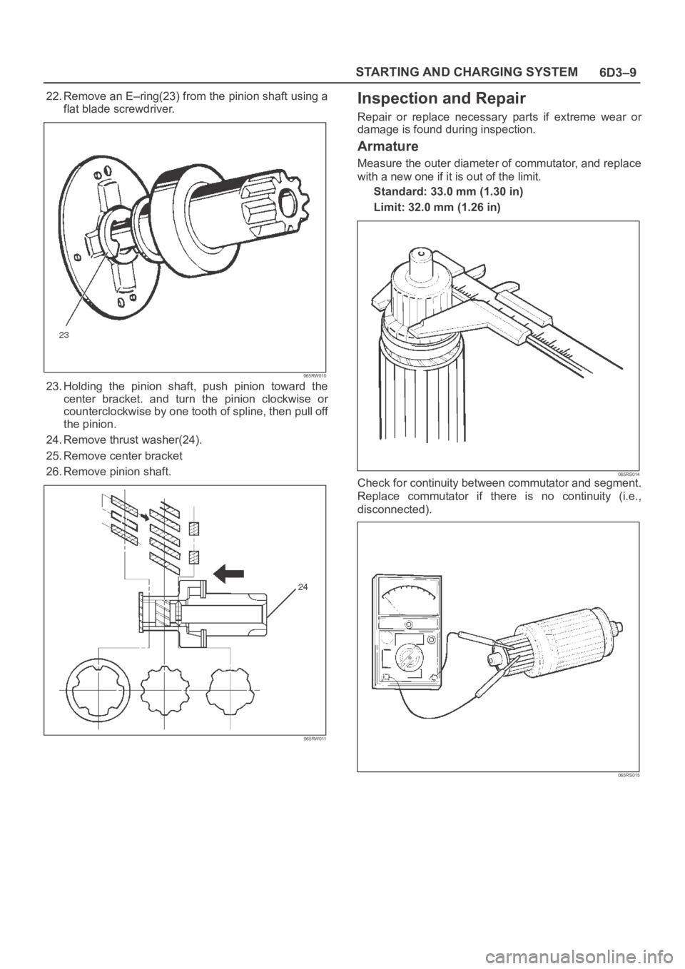
22. Remove an E–ring(23) from the pinion shaft using a
flat blade screwdriver.
065RW010
23. Holding the pinion shaft, push pinion toward the
center bracket. and turn the pinion clockwise or
counterclockwise by one tooth of spline, then pull off
the pinion.
24. Remove thrust washer(24).
25. Remove center bracket
26. Remove pinion shaft.
065RW011
Inspection and Repair
Repair or replace necessary parts if extreme wear or
damage is found during inspection.
Armature
Measure the outer diameter of commutator, and replace
with a new one if it is out of the limit.
Standard: 33.0 mm (1.30 in)
Limit: 32.0 mm (1.26 in)
065RS014Check for continuity between commutator and segment.
Replace commutator if there is no continuity (i.e.,
disconnected).
065RS015
Page 1104 of 6000
6D3–13 STARTING AND CHARGING SYSTEM
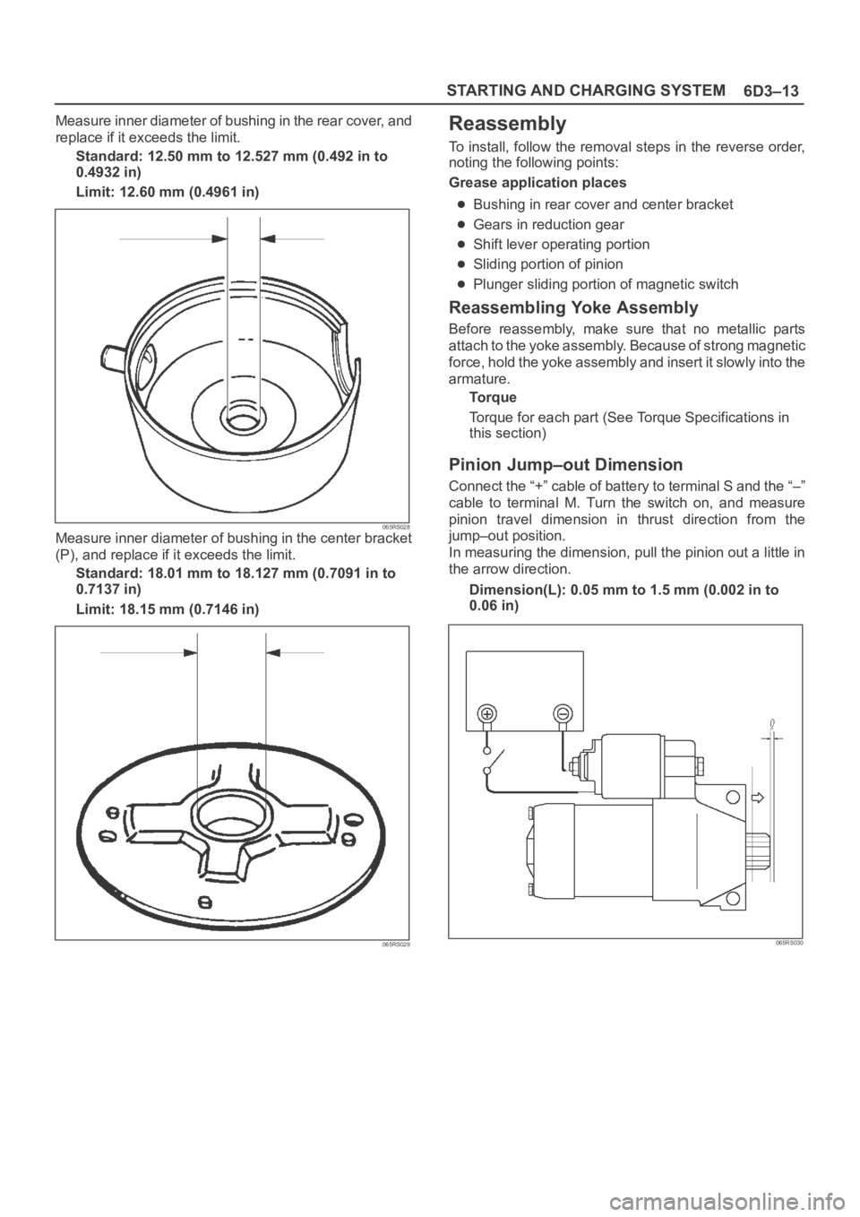
Measure inner diameter of bushing in the rear cover, and
replace if it exceeds the limit.
Standard: 12.50 mm to 12.527 mm (0.492 in to
0.4932 in)
Limit: 12.60 mm (0.4961 in)
065RS028Measure inner diameter of bushing in the center bracket
(P), and replace if it exceeds the limit.
Standard: 18.01 mm to 18.127 mm (0.7091 in to
0.7137 in)
Limit: 18.15 mm (0.7146 in)
065RS029
Reassembly
To install, follow the removal steps in the reverse order,
noting the following points:
Grease application places
Bushing in rear cover and center bracket
Gears in reduction gear
Shift lever operating portion
Sliding portion of pinion
Plunger sliding portion of magnetic switch
Reassembling Yoke Assembly
Before reassembly, make sure that no metallic parts
attach to the yoke assembly. Because of strong magnetic
force, hold the yoke assembly and insert it slowly into the
armature.
To r q u e
Torque for each part (See Torque Specifications in
this section)
Pinion Jump–out Dimension
Connect the “+” cable of battery to terminal S and the “–”
cable to terminal M. Turn the switch on, and measure
pinion travel dimension in thrust direction from the
jump–out position.
In measuring the dimension, pull the pinion out a little in
the arrow direction.
Dimension(L): 0.05 mm to 1.5 mm (0.002 in to
0.06 in)
065RS030
Page 1179 of 6000
6E–62
ENGINE DRIVEABILITY AND EMISSIONS
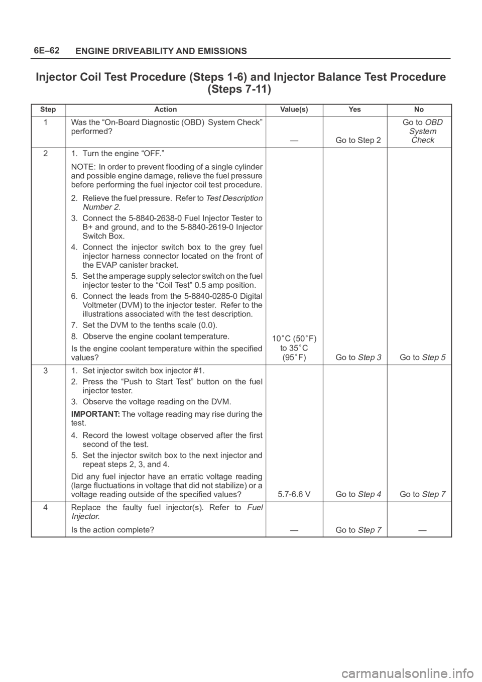
Injector Coil Test Procedure (Steps 1-6) and Injector Balance Test Procedure
(Steps 7-11)
StepActionVa l u e ( s )Ye sNo
1Was the “On-Board Diagnostic (OBD) System Check”
performed?
—Go to Step 2
Go to OBD
System
Check
21. Turn the engine “OFF.”
NOTE: In order to prevent flooding of a single cylinder
and possible engine damage, relieve the fuel pressure
before performing the fuel injector coil test procedure.
2. Relieve the fuel pressure. Refer to
Test Description
Number 2.
3. Connect the 5-8840-2638-0 Fuel Injector Tester to
B+ and ground, and to the 5-8840-2619-0 Injector
Switch Box.
4. Connect the injector switch box to the grey fuel
injector harness connector located on the front of
the EVAP canister bracket.
5. Set the amperage supply selector switch on the fuel
injector tester to the “Coil Test” 0.5 amp position.
6. Connect the leads from the 5-8840-0285-0 Digital
Voltmeter (DVM) to the injector tester. Refer to the
illustrations associated with the test description.
7. Set the DVM to the tenths scale (0.0).
8. Observe the engine coolant temperature.
Is the engine coolant temperature within the specified
values?
10C (50F)
to 35
C
(95
F)Go to Step 3Go to Step 5
31. Set injector switch box injector #1.
2. Press the “Push to Start Test” button on the fuel
injector tester.
3. Observe the voltage reading on the DVM.
IMPORTANT:The voltage reading may rise during the
test.
4. Record the lowest voltage observed after the first
second of the test.
5. Set the injector switch box to the next injector and
repeat steps 2, 3, and 4.
Did any fuel injector have an erratic voltage reading
(large fluctuations in voltage that did not stabilize) or a
voltage reading outside of the specified values?
5.7-6.6 VGo to Step 4Go to Step 7
4Replace the faulty fuel injector(s). Refer to Fuel
Injector.
Is the action complete?—Go to Step 7—
Page 1197 of 6000
6E–80
ENGINE DRIVEABILITY AND EMISSIONS
Circuit Description
The electronic Ignition system uses a coil-at-plug method
of spark distribution. In this type of ignition system, the
powertrain control module (PCM) triggers the correct
driver inside the ignition coil, which then triggers the
correct ignition coil based on the 58X signal received from
the crankshaft position sensor (CKP). The spark plug
connected to the coil fires when the ICM opens the ground
circuit for the coil’s primary circuit.
During crank, the PCM monitors the CKP 58X signal. The
CKP signal is used to determine which cylinder will fire
first. After the CKP 58X signal has been processed by the
PCM, it will command all six injectors to allow a priming
shot of fuel for all the cylinders. After the priming, the
injectors are left “OFF” during the next six 58X reference
pulses from the CKP. This allows each cylinder a chance
to use the fuel from the priming shot. During this waiting
period, a camshaft position (CMP) signal pulse will have
been received by the PCM. The CMP signal allows the
PCM to operate the injectors sequentially based on
camshaft position. If the camshaft position signal is not
present at start-up, the PCM will begin sequential fuel
delivery with a 1-in-6 chance that fuel delivery is correct.
The engine will run without a CMP signal, but will set a
DTC code.
Diagnostic Aids
An intermittent problem may be caused by a poor
connection, rubbed-through wire insulation or a wire
broken inside the insulation. Check for the following
items:
Poor connection or damaged harness – Inspect the
PCM harness and connectors for improper mating,
broken locks, improperly formed or damaged
terminals, poor terminal-to-wire connection, and
damaged harness.
Faulty engine coolant temperature sensor – Using
Tech 2, compare engine coolant temperature with
intake air temperature on a completely cool engine.
Engine coolant temperature should be within 10
C of
intake air temperature. If not, replace the ECT sensor.
Test Description
Number(s) below refer to the step number(s) on the
Diagnostic Chart.
5. An obvious cause of low fuel pressure would be an
empty fuel tank.
6. The engine will easily start and run if a few injectors
are disabled. It is not necessary to test all injectors
at this time since this step is only a test to verify that
all of the injectors have not been disabled by fuel
contamination.
7. A blinking test light verifies that the PCM is
monitoring the 58X crankshaft reference signal and
is capable of activating the injectors. If there is an
open or shorted driver circuit, DTCs 201-206 should
be set.
19.By using a spark tester, each ignition coil’s ability to
produce 25,000 volts is verified.
25.If there is an open or shorted driver circuit, DTCs
201-206 should be set. All six injector driver circuits
can be checked at one time without removing the
intake manifold if a 5-8840-2636-0 test light is
available. This is the alternative procedure:
With the ignition “OFF,” disconnect the gray
connector located at the rear of the air filter, attached
to a bracket on the purge canister.
Connect test light 5-8840-2636-0 to the connector.
Do any of the light constantly illuminate or fail to blink
when the engine is cranked? If so, repair the short or
open circuit, or replace the PCM if indicated.
This procedure only tests the driver circuit as far as the
test connection, so step 31 is added to test the circuit all
the way to the injector.
Page 1199 of 6000
6E–82
ENGINE DRIVEABILITY AND EMISSIONS
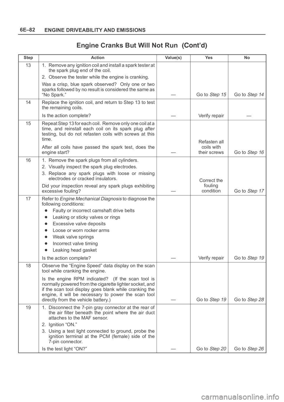
Engine Cranks But Will Not Run
StepNo Ye s Va l u e ( s ) Action
131. Remove any ignition coil and install a spark tester at
the spark plug end of the coil.
2. Observe the tester while the engine is cranking.
Was a crisp, blue spark observed? Only one or two
sparks followed by no result is considered the same as
“No Spark.”
—Go to Step 15Go to Step 14
14Replace the ignition coil, and return to Step 13 to test
the remaining coils.
Is the action complete?
—Verify repair—
15Repeat Step 13 for each coil. Remove only one coil at a
time, and reinstall each coil on its spark plug after
testing, but do not refasten coils with screws at this
time.
After all coils have passed the spark test, does the
engine start?
—
Refasten all
coils with
their screws
Go to Step 16
161. Remove the spark plugs from all cylinders.
2. Visually inspect the spark plug electrodes.
3. Replace any spark plugs with loose or missing
electrodes or cracked insulators.
Did your inspection reveal any spark plugs exhibiting
excessive fouling?
—
Correct the
fouling
condition
Go to Step 17
17Refer to Engine Mechanical Diagnosis to diagnose the
following conditions:
Faulty or incorrect camshaft drive belts
Leaking or sticky valves or rings
Excessive valve deposits
Loose or worn rocker arms
Weak valve springs
Incorrect valve timing
Leaking head gasket
Is the action complete?
—Verify repairGo to Step 19
18Observe the “Engine Speed” data display on the scan
tool while cranking the engine.
Is the engine RPM indicated? (If the scan tool is
normally powered from the cigarette lighter socket, and
if the scan tool display goes blank while cranking the
engine, it will be necessary to power the scan tool
directly from the vehicle battery.)
—Go to Step 19Go to Step 28
191. Disconnect the 7-pin gray connector at the rear of
the air filter beneath the point where the air duct
attaches to the MAF sensor.
2. Ignition “ON.”
3. Using a test light connected to ground, probe the
ignition terminal at the PCM (female) side of the
7-pin connector.
Is the test light “ON?”
—Go to Step 20Go to Step 26
Page 1213 of 6000

6E–96
ENGINE DRIVEABILITY AND EMISSIONS
Knock Sensor (KS) System Check
(Engine Knock, Poor Performance, or Poor Economy)
StepActionVa l u e ( s )Ye sNo
1Is DTC P0325 or P0327 set?
—
Go to DTC
P0325 or
DTC P0327
Go to Step 2
2Run the engine at 1500 RPM.
Is there an internal engine knock?
—Go to Step 3Go to Step 4
3Repair the mechanical problem.
Is the action complete?
—Verify repair—
41. Install Tech 2.
2. Turn the ignition “ON.”
3. Cycle through the list until “Knock Retard” is
displayed.
Is knock retard at the specified value?
0Go to Step 6Go to Step 7
5Replace the PCM.
IMPORTANT:The replacement PCM must be
programmed. Refer to
UBS 98model year Immobilizer
Workshop Manual.
Is the action complete?—Verify repair—
61. Start the engine.
2. Monitor the knock retard display on Tech 2 while
changing the throttle setting to place different loads
on the engine.
Is knock retard at the specified value? (Turn the ignition
“OFF.”)
0Go to Step 9Go to Step 7
71. At the rear of the engine, behind the rear fuel
injector on the lift side, disconnect the 2-wire knock
sensor harness connector.
2. Attach the positive lead of DVM to B+.
3. On the m ain harness side of the connector, use th e
negative lead of the DVM to probe the connector pin
that is connected to the black wire.
Dose the DVM indicate the specified value?
(Reconnect the knock sensor harness.)
B+Go to Step 9Go to Step 8
8Repair the open black wire ground for the shield which
prevents stray electromagnetic pulses from affecting
the knock signal.
Is the action complete?
—Verify repair—
91. Reconnect the wire harness.
2. Set a DVM to AC voltage.
3. With the DVM, backprobe the PCM connector at
A2.
4. Tap the engine lift brackprobe with a socket
extension.
Did the DVM show an increase in AC voltage while
tapping on the lift bracket?
—System OKGo to Step 10
10Replace the knock sensor.
Is the action complete?
—Verify repair—
Page 1216 of 6000
6E–99 ENGINE DRIVEABILITY AND EMISSIONS
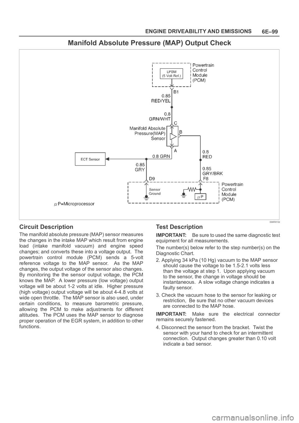
Manifold Absolute Pressure (MAP) Output Check
D06RW102
Circuit Description
The manifold absolute pressure (MAP) sensor measures
the changes in the intake MAP which result from engine
load (intake manifold vacuum) and engine speed
changes; and converts these into a voltage output. The
powertrain control module (PCM) sends a 5-volt
reference voltage to the MAP sensor. As the MAP
changes, the output voltage of the sensor also changes.
By monitoring the the sensor output voltage, the PCM
knows the MAP. A lower pressure (low voltage) output
voltage will be about 1-2 volts at idle. Higher pressure
(high voltage) output voltage will be about 4-4.8 volts at
wide open throttle. The MAP sensor is also used, under
certain conditions, to measure barometric pressure,
allowing the PCM to make adjustments for different
altitudes. The PCM uses the MAP sensor to diagnose
proper operation of the EGR system, in addition to other
functions.
Test Description
IMPORTANT:Be sure to used the same diagnostic test
equipment for all measurements.
The number(s) below refer to the step number(s) on the
Diagnostic Chart.
2. Applying 34 kPa (10 Hg) vacuum to the MAP sensor
should cause the voltage to be 1.5-2.1 volts less
than the voltage at step 1. Upon applying vacuum
to the sensor, the change in voltage should be
instantaneous. A slow voltage change indicates a
faulty sensor.
3. Check the vacuum hose to the sensor for leaking or
restriction, Be sure that no other vacuum devices
are connected to the MAP hose.
IMPORTANT:Make sure the electrical connector
remains securely fastened.
4. Disconnect the sensor from the bracket. Twist the
sensor with your hand to check for an intermittent
connection. Output changes greater than 0.10 volt
indicate a bad sensor.
Page 1309 of 6000
6E–192
ENGINE DRIVEABILITY AND EMISSIONS
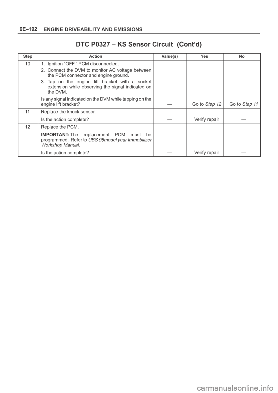
DTC P0327 – KS Sensor Circuit
StepNo Ye s Va l u e ( s ) Action
101. Ignition “OFF,” PCM disconnected.
2. Connect the DVM to monitor AC voltage between
the PCM connector and engine ground.
3. Tap on the engine lift bracket with a socket
extension while observing the signal indicated on
the DVM.
Is any signal indicated on the DVM while tapping on the
engine lift bracket?
—Go to Step 12Go to Step 11
11Replace the knock sensor.
Is the action complete?
—Verify repair—
12Replace the PCM.
IMPORTANT:The replacement PCM must be
programmed. Refer to
UBS 98model year Immobilizer
Workshop Manual.
Is the action complete?—Verify repair—