Page 1008 of 6000
6A–52
ENGINE MECHANICAL
Cylinder Head
Cylinder Head and Associated Parts
011RW008
Legend
(1) Spark Plug
(2) Cylinder Head Bolt
(3) Camshaft Drive Gear Pulley Fixing Bolt
(4) Camshaft Drive Gear Pulley
(5) Camshaft Bracket Fixing Bolt
(6) Camshaft Bracket
(7) Camshaft Exhaust(8) Camshaft Intake
(9) Retainer Fixing Bolt
(10) Retainer Assembly
(11) Tappet with Shim
(12) Split Collar
(13) Valve Spring and Spring Upper Seat
(14) Valve
Disassembly
NOTE:
During disassembly, be sure that the valve train
components are kept together and identified so that
they can be reinstalled in their original locations.
Before removing the cylinder head from the engine
and before disassembling the valve mechanism,
perform a compression test and note the results.
1. Remove camshaft drive gear pulley fixing bolt (3),
then pulley (4).
Page 1009 of 6000
6A–53
ENGINE MECHANICAL
2. Remove camshaft bracket fixing bolt (5), camshaft
bracket (6), then camshaft exhaust (7), and intake
side (8).
3. Remove tappet with shim (11).
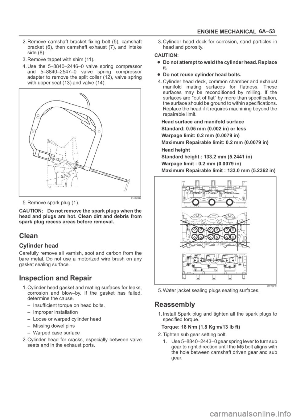
4. Use the 5–8840–2446–0 valve spring compressor
and 5–8840–2547–0 valve spring compressor
adapter to remove the split collar (12), valve spring
with upper seat (13) and valve (14).
014RW042
5. Remove spark plug (1).
CAUTION: Do not remove the spark plugs when the
head and plugs are hot. Clean dirt and debris from
spark plug recess areas before removal.
Clean
Cylinder head
Carefully remove all varnish, soot and carbon from the
bare metal. Do not use a motorized wire brush on any
gasket sealing surface.
Inspection and Repair
1. Cylinder head gasket and mating surfaces for leaks,
corrosion and blow–by. If the gasket has failed,
determine the cause.
– Insufficient torque on head bolts.
– Improper installation
– Loose or warped cylinder head
– Missing dowel pins
– Warped case surface
2. Cylinder head for cracks, especially between valve
seats and in the exhaust ports.3. Cylinder head deck for corrosion, sand particles in
head and porosity.
CAUTION:
Do not attempt to weld the cylinder head. Replace
it.
Do not reuse cylinder head bolts.
4. Cylinder head deck, common chamber and exhaust
manifold mating surfaces for flatness. These
surfaces may be reconditioned by milling. If the
surfaces are “out of flat” by more than specification,
the surface should be ground to within specifications.
Replace the head if it requires machining beyond the
repairable limit.
Head surface and manifold surface
Standard: 0.05 mm (0.002 in) or less
Warpage limit: 0.2 mm (0.0079 in)
Maximum Repairable limit: 0.2 mm (0.0079 in)
Head height
Standard height : 133.2 mm (5.2441 in)
Warpage limit : 0.2 mm (0.0079 in)
Maximum Repairable limit : 133.0 mm (5.2362 in)
011RW019
5. Water jacket sealing plugs seating surfaces.
Reassembly
1. Install Spark plug and tighten all the spark plugs to
specified torque.
Torque: 18 Nꞏm (1.8 Kgꞏm/13 lb ft)
2. Tighten sub gear setting bolt.
1. Use 5–8840–2443–0 gear spring lever to turn sub
gear to right direction until the M5 bolt aligns with
the hole between camshaft driven gear and sub
gear.
Page 1010 of 6000
6A–54
ENGINE MECHANICAL
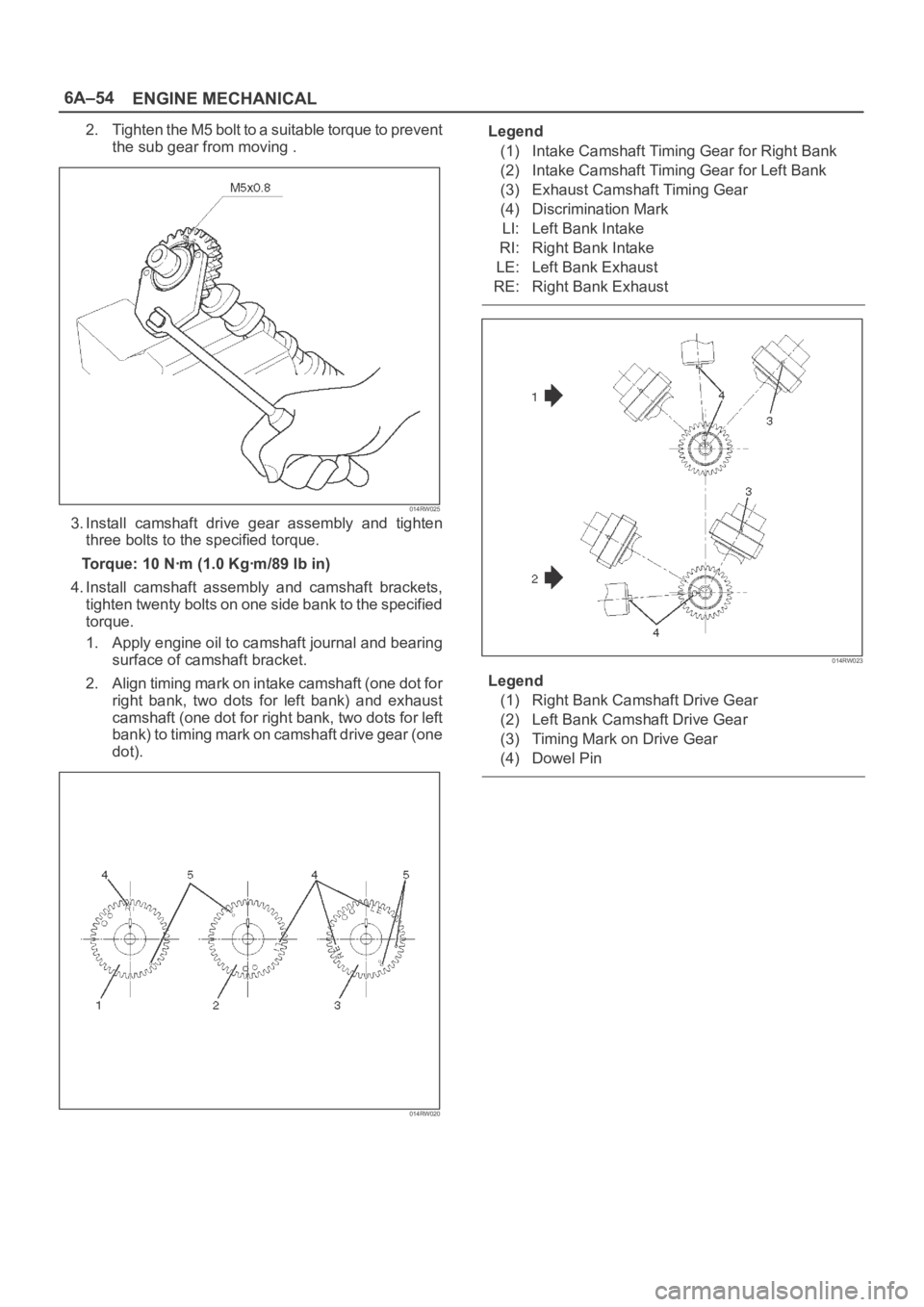
2. Tighten the M5 bolt to a suitable torque to prevent
the sub gear from moving .
014RW025
3. Install camshaft drive gear assembly and tighten
three bolts to the specified torque.
Torque: 10 Nꞏm (1.0 Kgꞏm/89 lb in)
4. Install camshaft assembly and camshaft brackets,
tighten twenty bolts on one side bank to the specified
torque.
1. Apply engine oil to camshaft journal and bearing
surface of camshaft bracket.
2. Align timing mark on intake camshaft (one dot for
right bank, two dots for left bank) and exhaust
camshaft (one dot for right bank, two dots for left
bank) to timing mark on camshaft drive gear (one
dot).
014RW020
Legend
(1) Intake Camshaft Timing Gear for Right Bank
(2) Intake Camshaft Timing Gear for Left Bank
(3) Exhaust Camshaft Timing Gear
(4) Discrimination Mark
LI: Left Bank Intake
RI: Right Bank Intake
LE: Left Bank Exhaust
RE: Right Bank Exhaust
014RW023
Legend
(1) Right Bank Camshaft Drive Gear
(2) Left Bank Camshaft Drive Gear
(3) Timing Mark on Drive Gear
(4) Dowel Pin
Page 1012 of 6000
6A–56
ENGINE MECHANICAL
Valve Spring, Oil Controller, Valve, Valve Guide
Valve Spring, Oil Controller, Valve, Valve Guide and Associated Parts
014RW039
Legend
(1) Camshaft Bracket Fixing Bolts
(2) Camshaft Assembly Inlet
(3) Camshaft Assembly Exhaust
(4) Shim
(5) Tappet
(6) Split Collar(7) Spring Upper Seat
(8) Valve Spring
(9) Oil Controller
(10) Spring Lower Seat
(11) Valve Guide
(12) Valve
Disassembly
1. Remove camshaft bracket fixing bolts (1).
2. Remove camshaft assembly (intake).3. Remove camshaft assembly (Exhaust side).
4. Remove shim (4) and tappet (5).
Page 1019 of 6000
6A–63
ENGINE MECHANICAL
Camshaft
Camshaft and Associated Parts
014RW040
Legend
(1) Camshaft Bracket Fixing Bolt
(2) Camshaft Bracket
(3) Camshaft Assembly Intake
(4) Camshaft Assembly Exhaust
(5) Pulley Fixing Bolt(6) Camshaft Drive Gear Pulley
(7) Retainer Fixing Bolt
(8) Retainer
(9) Camshaft Drive Gear
(10) Oil Seal
Disassembly
1. Remove fixing bolt (5) for camshaft drive gear pulley
using the 5–8840–2447–0 universal holder.
Page 1020 of 6000
6A–64
ENGINE MECHANICAL
014RW060
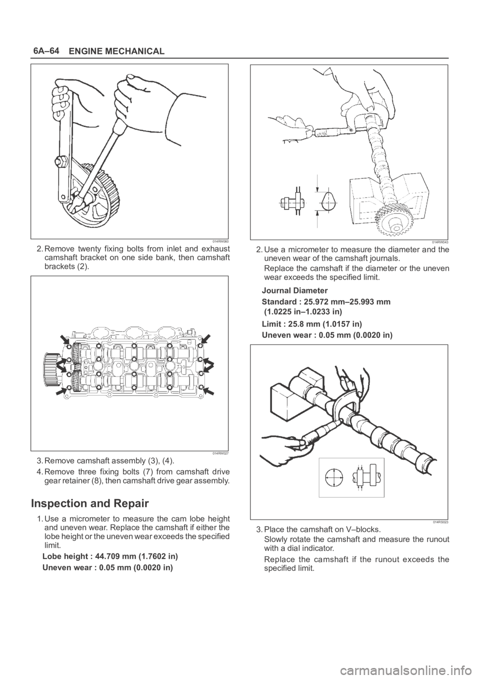
2. Remove twenty fixing bolts from inlet and exhaust
camshaft bracket on one side bank, then camshaft
brackets (2).
014RW027
3. Remove camshaft assembly (3), (4).
4. Remove three fixing bolts (7) from camshaft drive
gear retainer (8), then camshaft drive gear assembly.
Inspection and Repair
1. Use a micrometer to measure the cam lobe height
and uneven wear. Replace the camshaft if either the
lobe height or the uneven wear exceeds the specified
limit.
Lobe height : 44.709 mm (1.7602 in)
Uneven wear : 0.05 mm (0.0020 in)
014RW043
2. Use a micrometer to measure the diameter and the
uneven wear of the camshaft journals.
Replace the camshaft if the diameter or the uneven
wear exceeds the specified limit.
Journal Diameter
Standard : 25.972 mm–25.993 mm
(1.0225 in–1.0233 in)
Limit : 25.8 mm (1.0157 in)
Uneven wear : 0.05 mm (0.0020 in)
014RS023
3. Place the camshaft on V–blocks.
Slowly rotate the camshaft and measure the runout
with a dial indicator.
Replace the camshaft if the runout exceeds the
specified limit.
Page 1021 of 6000
6A–65
ENGINE MECHANICAL
Runout
Limit : 0.1 mm (0.0039 in)
014RW044
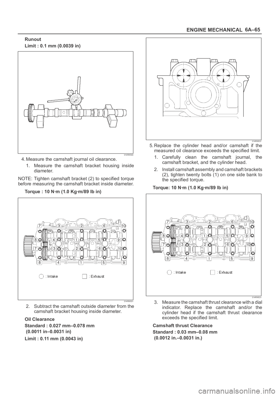
4. Measure the camshaft journal oil clearance.
1. Measure the camshaft bracket housing inside
diameter.
NOTE: Tighten camshaft bracket (2) to specified torque
before measuring the camshaft bracket inside diameter.
Torque : 10 Nꞏm (1.0 Kgꞏm/89 lb in)
014RW031
2. Subtract the camshaft outside diameter from the
camshaft bracket housing inside diameter.
Oil Clearance
Standard : 0.027 mm–0.078 mm
(0.0011 in–0.0031 in)
Limit : 0.11 mm (0.0043 in)
014RW037
5. Replace the cylinder head and/or camshaft if the
measured oil clearance exceeds the specified limit.
1. Carefully clean the camshaft journal, the
camshaft bracket, and the cylinder head.
2. Install camshaft assembly and camshaft brackets
(2), tighten twenty bolts (1) on one side bank to
the specified torque.
Torque: 10 Nꞏm (1.0 Kgꞏm/89 lb in)
014RW031
3. Measure the camshaft thrust clearance with a dial
indicator. Replace the camshaft and/or the
cylinder head if the camshaft thrust clearance
exceeds the specified limit.
Camshaft thrust Clearance
Standard : 0.03 mm–0.08 mm
(0.0012 in.–0.0031 in.)
Page 1022 of 6000
6A–66
ENGINE MECHANICAL
Limit : 0.12 mm (0.0047 mm)
014RW035
Reassembly
1. Install camshaft drive gear assembly and tighten
three bolts to specified torque.
Torque: 10 Nꞏm (1.0 Kgꞏm/89 lb in)
2. Tighten sub gear setting bolt.
1. Use 5–8840–2443–0 to turn sub gear to right
direction until the M5 bolt hole aligns between
camshaft driven gear and sub gear.
2. Tighten M5 bolt suitable torque for prevent
moving the sub gear.
014RW041
3. Install camshaft assembly and camshaft brackets,
tighten twenty bolts on one side bank to the specified
torque.
1. Apply engine oil to camshaft journal and bearing
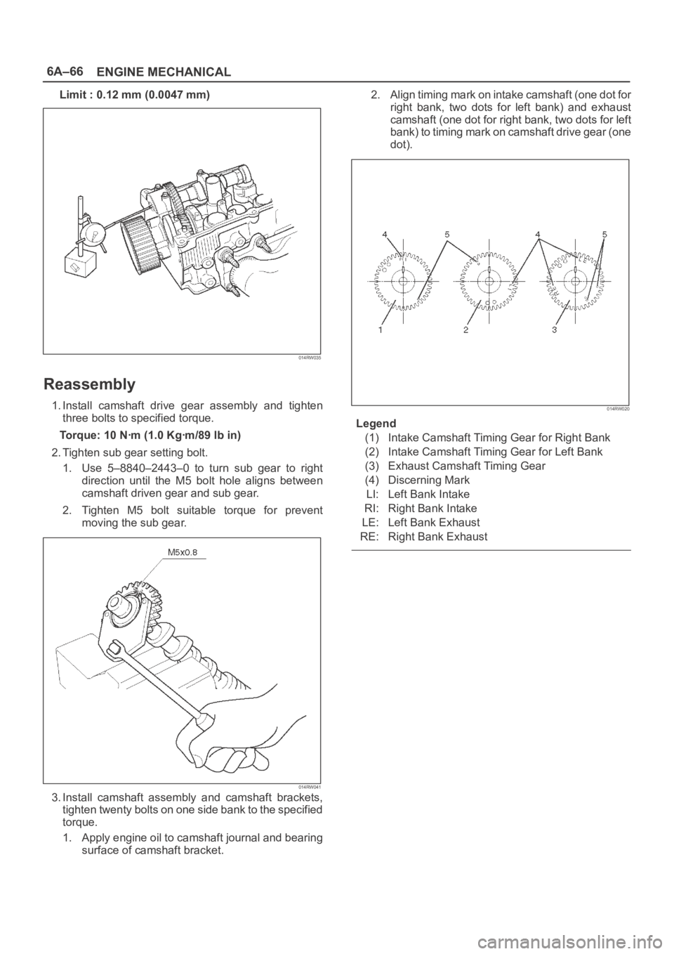
surface of camshaft bracket.2. Align timing mark on intake camshaft (one dot for
right bank, two dots for left bank) and exhaust
camshaft (one dot for right bank, two dots for left
bank) to timing mark on camshaft drive gear (one
dot).
014RW020
Legend
(1) Intake Camshaft Timing Gear for Right Bank
(2) Intake Camshaft Timing Gear for Left Bank
(3) Exhaust Camshaft Timing Gear
(4) Discerning Mark
LI: Left Bank Intake
RI: Right Bank Intake
LE: Left Bank Exhaust
RE: Right Bank Exhaust