1998 NISSAN PICK-UP relay
[x] Cancel search: relayPage 1263 of 1659
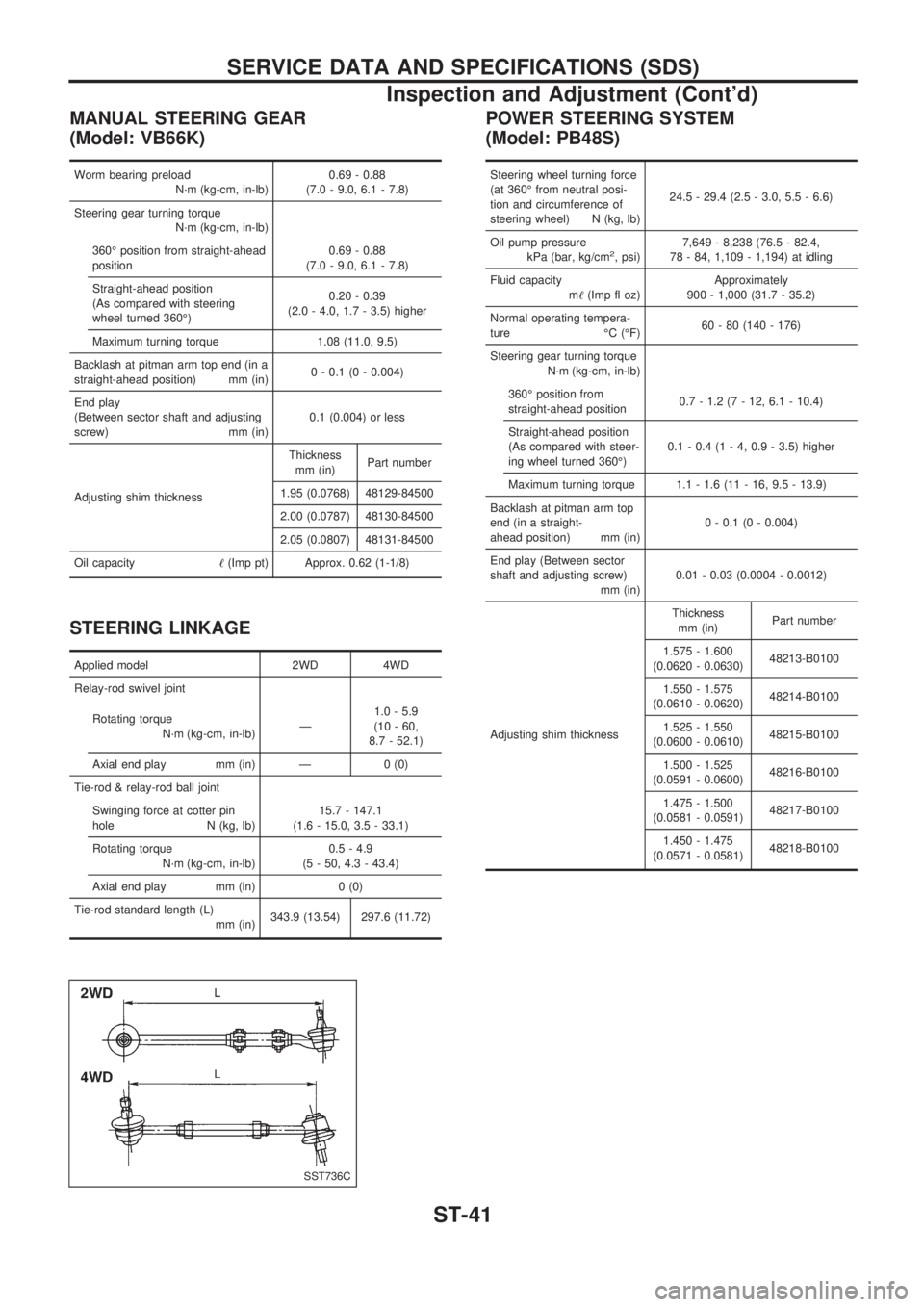
MANUAL STEERING GEAR
(Model: VB66K)
Worm bearing preload
N´m (kg-cm, in-lb)0.69 - 0.88
(7.0 - 9.0, 6.1 - 7.8)
Steering gear turning torque
N´m (kg-cm, in-lb)
360É position from straight-ahead
position0.69 - 0.88
(7.0 - 9.0, 6.1 - 7.8)
Straight-ahead position
(As compared with steering
wheel turned 360É)0.20 - 0.39
(2.0 - 4.0, 1.7 - 3.5) higher
Maximum turning torque 1.08 (11.0, 9.5)
Backlash at pitman arm top end (in a
straight-ahead position) mm (in)0 - 0.1 (0 - 0.004)
End play
(Between sector shaft and adjusting
screw) mm (in)0.1 (0.004) or less
Adjusting shim thicknessThickness
mm (in)Part number
1.95 (0.0768) 48129-84500
2.00 (0.0787) 48130-84500
2.05 (0.0807) 48131-84500
Oil capacity!(Imp pt) Approx. 0.62 (1-1/8)
STEERING LINKAGE
Applied model 2WD 4WD
Relay-rod swivel joint
Rotating torque
N´m (kg-cm, in-lb)Ð1.0 - 5.9
(10 - 60,
8.7 - 52.1)
Axial end play mm (in) Ð 0 (0)
Tie-rod & relay-rod ball joint
Swinging force at cotter pin
hole N (kg, lb)15.7 - 147.1
(1.6 - 15.0, 3.5 - 33.1)
Rotating torque
N´m (kg-cm, in-lb)0.5 - 4.9
(5 - 50, 4.3 - 43.4)
Axial end play mm (in) 0 (0)
Tie-rod standard length (L)
mm (in)343.9 (13.54) 297.6 (11.72)
POWER STEERING SYSTEM
(Model: PB48S)
Steering wheel turning force
(at 360É from neutral posi-
tion and circumference of
steering wheel) N (kg, lb)24.5 - 29.4 (2.5 - 3.0, 5.5 - 6.6)
Oil pump pressure
kPa (bar, kg/cm
2, psi)7,649 - 8,238 (76.5 - 82.4,
78 - 84, 1,109 - 1,194) at idling
Fluid capacity
m!(Imp fl oz)Approximately
900 - 1,000 (31.7 - 35.2)
Normal operating tempera-
ture ÉC (ÉF)60 - 80 (140 - 176)
Steering gear turning torque
N´m (kg-cm, in-lb)
360É position from
straight-ahead position0.7 - 1.2 (7 - 12, 6.1 - 10.4)
Straight-ahead position
(As compared with steer-
ing wheel turned 360É)0.1 - 0.4 (1 - 4, 0.9 - 3.5) higher
Maximum turning torque 1.1 - 1.6 (11 - 16, 9.5 - 13.9)
Backlash at pitman arm top
end (in a straight-
ahead position) mm (in)0 - 0.1 (0 - 0.004)
End play (Between sector
shaft and adjusting screw)
mm (in)0.01 - 0.03 (0.0004 - 0.0012)
Adjusting shim thicknessThickness
mm (in)Part number
1.575 - 1.600
(0.0620 - 0.0630)48213-B0100
1.550 - 1.575
(0.0610 - 0.0620)48214-B0100
1.525 - 1.550
(0.0600 - 0.0610)48215-B0100
1.500 - 1.525
(0.0591 - 0.0600)48216-B0100
1.475 - 1.500
(0.0581 - 0.0591)48217-B0100
1.450 - 1.475
(0.0571 - 0.0581)48218-B0100
SST736C
SERVICE DATA AND SPECIFICATIONS (SDS)
Inspection and Adjustment (Cont'd)
ST-41
Page 1296 of 1659
ELECTRICAL SYSTEM
SECTION
EL
When you read wiring diagrams:
lRead GI section, ``HOW TO READ WIRING DIAGRAMS''.
When you perform trouble diagnoses, read GI section, ``HOW TO FOLLOW FLOW CHART IN
TROUBLE DIAGNOSES'' and ``HOW TO PERFORM EFFICIENT DIAGNOSIS FOR AN ELECTRI-
CAL INCIDENT''.
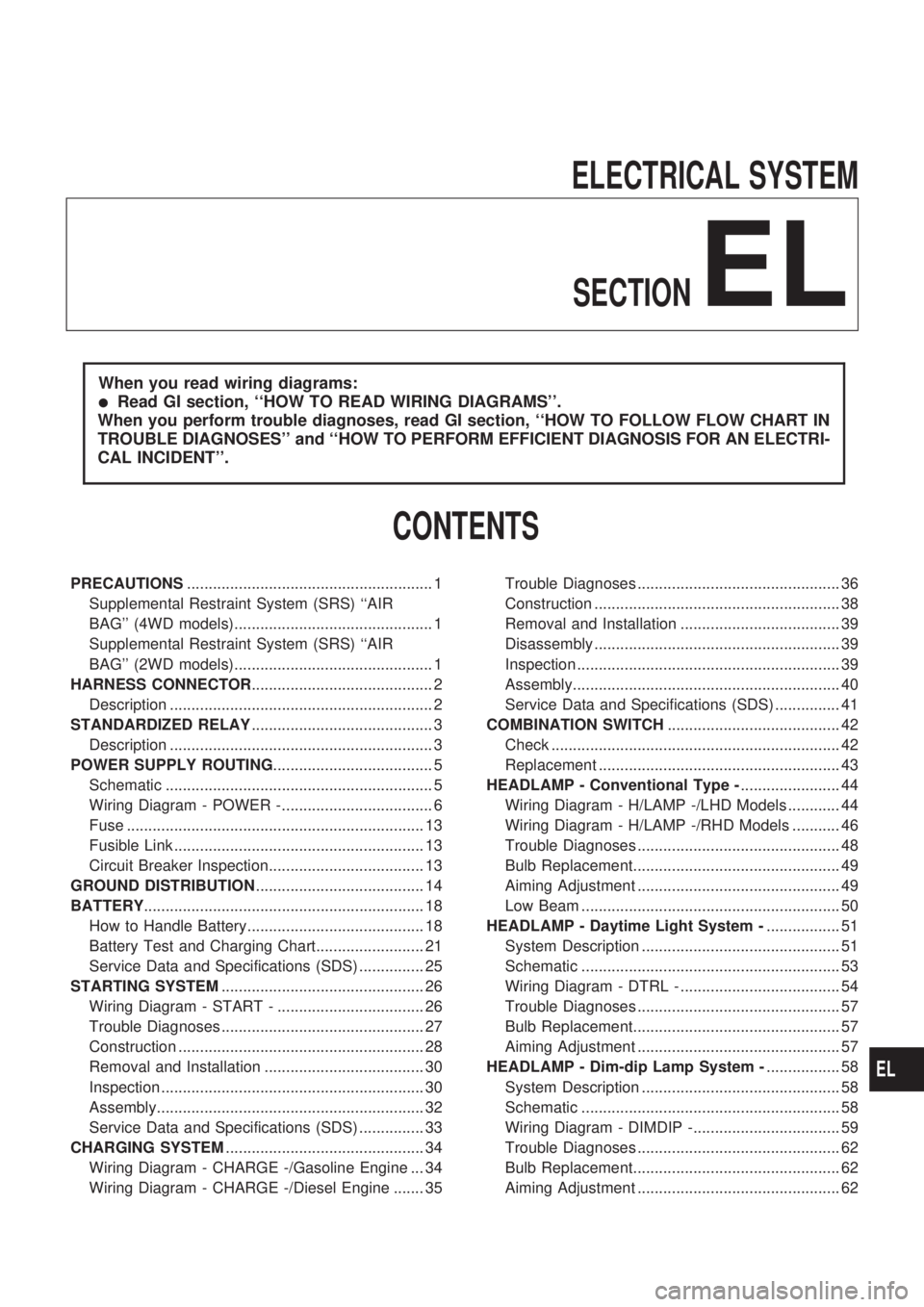
CONTENTS
PRECAUTIONS......................................................... 1
Supplemental Restraint System (SRS) ``AIR
BAG'' (4WD models).............................................. 1
Supplemental Restraint System (SRS) ``AIR
BAG'' (2WD models).............................................. 1
HARNESS CONNECTOR.......................................... 2
Description ............................................................. 2
STANDARDIZED RELAY.......................................... 3
Description ............................................................. 3
POWER SUPPLY ROUTING..................................... 5
Schematic .............................................................. 5
Wiring Diagram - POWER -................................... 6
Fuse ..................................................................... 13
Fusible Link .......................................................... 13
Circuit Breaker Inspection.................................... 13
GROUND DISTRIBUTION....................................... 14
BATTERY................................................................. 18
How to Handle Battery......................................... 18
Battery Test and Charging Chart......................... 21
Service Data and Specifications (SDS) ............... 25
STARTING SYSTEM............................................... 26
Wiring Diagram - START - .................................. 26
Trouble Diagnoses ............................................... 27
Construction ......................................................... 28
Removal and Installation ..................................... 30
Inspection ............................................................. 30
Assembly.............................................................. 32
Service Data and Specifications (SDS) ............... 33
CHARGING SYSTEM.............................................. 34
Wiring Diagram - CHARGE -/Gasoline Engine ... 34
Wiring Diagram - CHARGE -/Diesel Engine ....... 35Trouble Diagnoses ............................................... 36
Construction ......................................................... 38
Removal and Installation ..................................... 39
Disassembly ......................................................... 39
Inspection ............................................................. 39
Assembly.............................................................. 40
Service Data and Specifications (SDS) ............... 41
COMBINATION SWITCH........................................ 42
Check ................................................................... 42
Replacement ........................................................ 43
HEADLAMP - Conventional Type -....................... 44
Wiring Diagram - H/LAMP -/LHD Models ............ 44
Wiring Diagram - H/LAMP -/RHD Models ........... 46
Trouble Diagnoses ............................................... 48
Bulb Replacement................................................ 49
Aiming Adjustment ............................................... 49
Low Beam ............................................................ 50
HEADLAMP - Daytime Light System -................. 51
System Description .............................................. 51
Schematic ............................................................ 53
Wiring Diagram - DTRL - ..................................... 54
Trouble Diagnoses ............................................... 57
Bulb Replacement................................................ 57
Aiming Adjustment ............................................... 57
HEADLAMP - Dim-dip Lamp System -................. 58
System Description .............................................. 58
Schematic ............................................................ 58
Wiring Diagram - DIMDIP -.................................. 59
Trouble Diagnoses ............................................... 62
Bulb Replacement................................................ 62
Aiming Adjustment ............................................... 62
EL
Page 1301 of 1659
Description
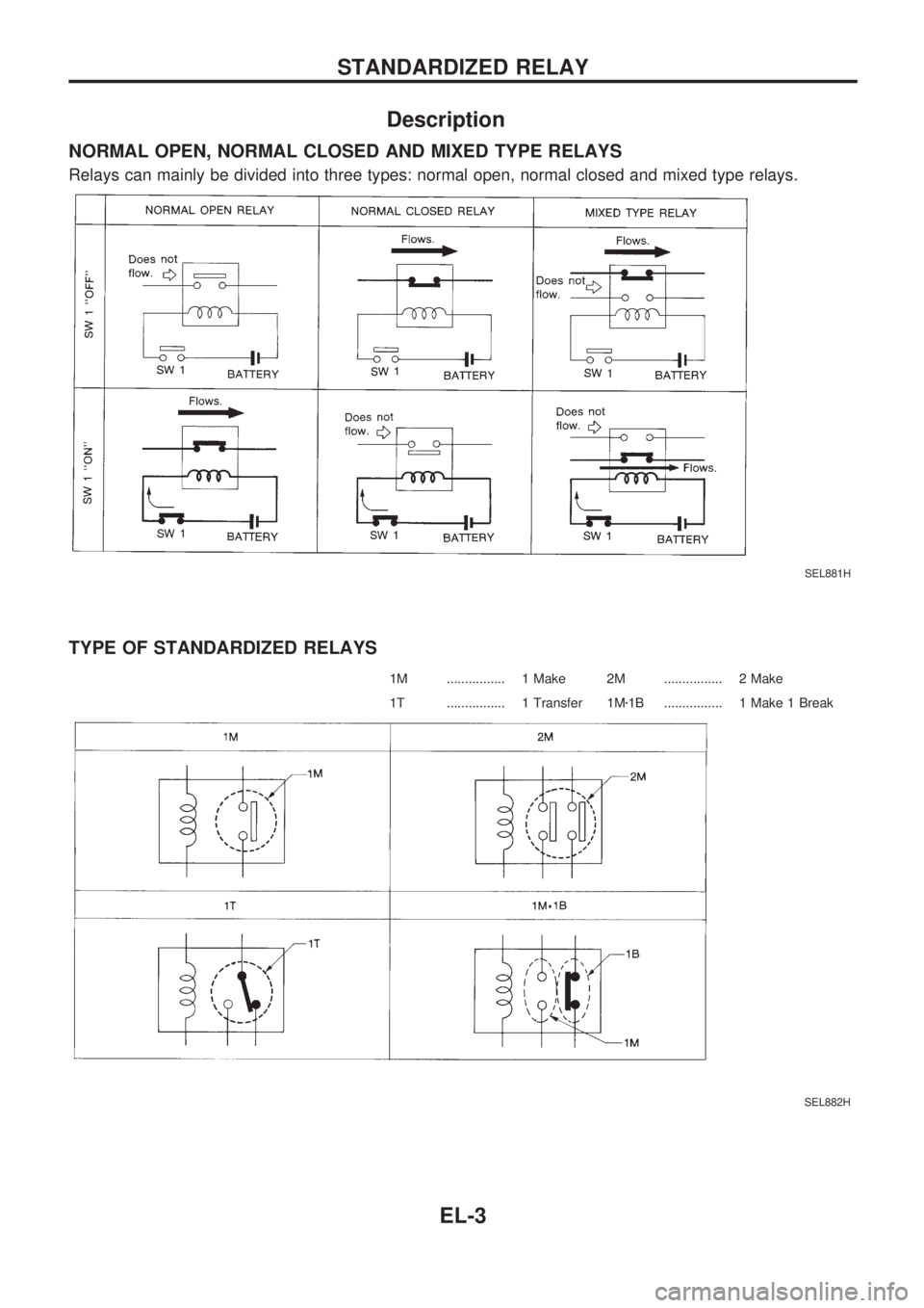
NORMAL OPEN, NORMAL CLOSED AND MIXED TYPE RELAYS
Relays can mainly be divided into three types: normal open, normal closed and mixed type relays.
TYPE OF STANDARDIZED RELAYS
1M ................ 1 Make 2M ................ 2 Make
1T ................ 1 Transfer 1Mz1B ................ 1 Make 1 Break
SEL881H
SEL882H
STANDARDIZED RELAY
EL-3
Page 1302 of 1659
SEL661TA
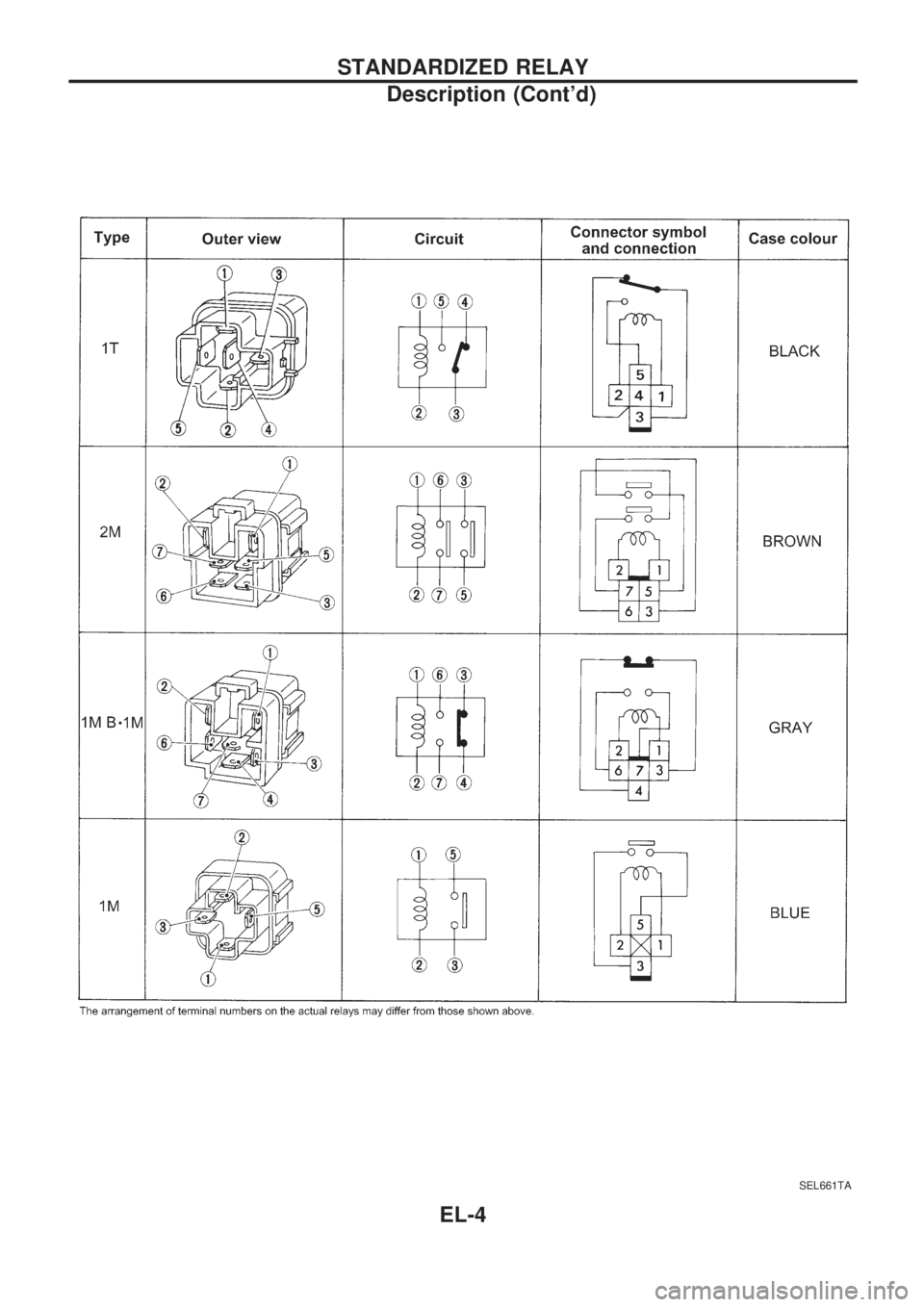
STANDARDIZED RELAY
Description (Cont'd)
EL-4
Page 1312 of 1659
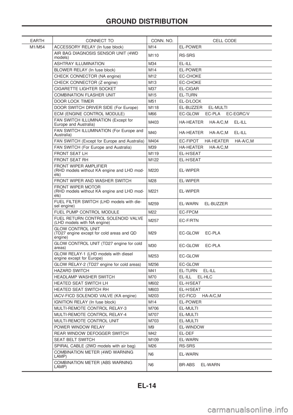
EARTH CONNECT TO CONN. NO. CELL CODE
M1/M54 ACCESSORY RELAY (In fuse block) M14 EL-POWER
AIR BAG DIAGNOSIS SENSOR UNIT (4WD
models)M110 RS-SRS
ASHTRAY ILLUMINATION M34 EL-ILL
BLOWER RELAY (In fuse block) M14 EL-POWER
CHECK CONNECTOR (NA engine) M12 EC-CHOKE
CHECK CONNECTOR (Z engine) M13 EC-CHOKE
CIGARETTE LIGHTER SOCKET M37 EL-CIGAR
COMBINATION FLASHER UNIT M15 EL-TURN
DOOR LOCK TIMER M51 EL-D/LOCK
DOOR SWITCH DRIVER SIDE (For Europe) M118 EL-BUZZER EL-MULTI
ECM (ENGINE CONTROL MODULE) M66 EC-GLOW EC-PLA EC-EGRC/V
FAN SWITCH ILLUMINATION (Except for
Europe and Australia)M403 HA-HEATER HA-A/C,M EL-ILL
FAN SWITCH ILLUMINATION (For Europe and
Australia)M40 HA-HEATER HA-A/C,M EL-ILL
FAN SWITCH (Except for Europe and Australia) M404 EC-FIPOT HA-HEATER HA-A/C,M
FAN SWITCH (For Europe and Australia) M39 HA-HEATER HA-A/C,M
FRONT SEAT LH M119 EL-H/SEAT
FRONT SEAT RH M122 EL-H/SEAT
FRONT WIPER AMPLIFIER
(RHD models without KA engine and LHD mod-
els)M220 EL-WIPER
FRONT WIPER AND WASHER SWITCH M28 EL-WIPER
FRONT WIPER MOTOR
(RHD models without KA engine and LHD mod-
els)M221 EL-WIPER
FUEL FILTER SWITCH (LHD models with die-
sel engine)M259 EL-WARN EL-BUZZER
FUEL PUMP CONTROL MODULE M22 EC-FPCM
FUEL RETURN CONTROL SOLENOID VALVE
(LHD models with NA engine)M257 EC-F/RTN
GLOW CONTROL UNIT
(TD27 engine except for cold areas and QD
engine)M29 EC-GLOW EC-PLA
GLOW CONTROL UNIT (TD27 engine for cold
areas)M30 EC-GLOW EC-PLA
GLOW RELAY-1 (LHD models with diesel
engine except for Europe)M253 EC-GLOW
GLOW RELAY-2 (TD27 engine for cold areas) M256 EC-GLOW
HAZARD SWITCH M41 EL-TURN EL-ILL
HEADLAMP WASHER SWITCH M70 EL-ILL EL-HLC
HEATED SEAT SWITCH LH M602 EL-H/SEAT
HEATED SEAT SWITCH RH M603 EL-H/SEAT
IACV-FICD SOLENOID VALVE (KA engine) M203 EC-FICD HA-A/C,M
IGNITION RELAY (In fuse block) M14 EL-POWER
MULTI-REMOTE CONTROL RELAY-3 M706 EL-MULTI
MULTI-REMOTE CONTROL RELAY-4 M707 EL-MULTI
MULTI-REMOTE CONTROL UNIT M703 EL-MULTI
POWER WINDOW RELAY M9 EL-WINDOW
REAR WINDOW DEFOGGER SWITCH M42 EL-DEF
SEAT BELT SWITCH M109 EL-WARN
SPIRAL CABLE (2WD models with air bag) M26 RS-SRS
COMBINATION METER (4WD WARNING
LAMP)N6 EL-WARN
COMBINATION METER (ABS WARNING
LAMP)N6 BR-ABS EL-WARN
GROUND DISTRIBUTION
EL-14
Page 1315 of 1659
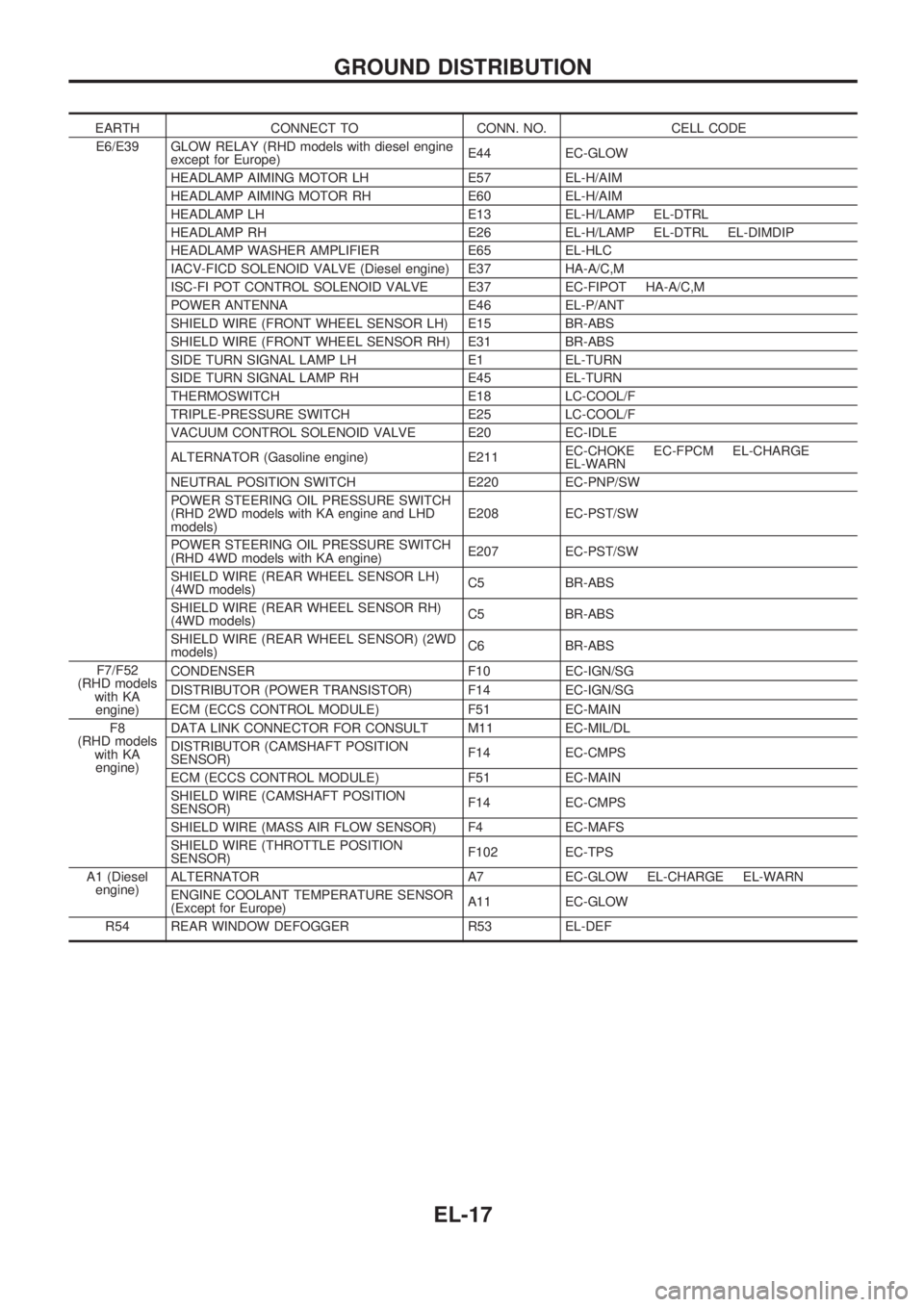
EARTH CONNECT TO CONN. NO. CELL CODE
E6/E39 GLOW RELAY (RHD models with diesel engine
except for Europe)E44 EC-GLOW
HEADLAMP AIMING MOTOR LH E57 EL-H/AIM
HEADLAMP AIMING MOTOR RH E60 EL-H/AIM
HEADLAMP LH E13 EL-H/LAMP EL-DTRL
HEADLAMP RH E26 EL-H/LAMP EL-DTRL EL-DIMDIP
HEADLAMP WASHER AMPLIFIER E65 EL-HLC
IACV-FICD SOLENOID VALVE (Diesel engine) E37 HA-A/C,M
ISC-FI POT CONTROL SOLENOID VALVE E37 EC-FIPOT HA-A/C,M
POWER ANTENNA E46 EL-P/ANT
SHIELD WIRE (FRONT WHEEL SENSOR LH) E15 BR-ABS
SHIELD WIRE (FRONT WHEEL SENSOR RH) E31 BR-ABS
SIDE TURN SIGNAL LAMP LH E1 EL-TURN
SIDE TURN SIGNAL LAMP RH E45 EL-TURN
THERMOSWITCH E18 LC-COOL/F
TRIPLE-PRESSURE SWITCH E25 LC-COOL/F
VACUUM CONTROL SOLENOID VALVE E20 EC-IDLE
ALTERNATOR (Gasoline engine) E211EC-CHOKE EC-FPCM EL-CHARGE
EL-WARN
NEUTRAL POSITION SWITCH E220 EC-PNP/SW
POWER STEERING OIL PRESSURE SWITCH
(RHD 2WD models with KA engine and LHD
models)E208 EC-PST/SW
POWER STEERING OIL PRESSURE SWITCH
(RHD 4WD models with KA engine)E207 EC-PST/SW
SHIELD WIRE (REAR WHEEL SENSOR LH)
(4WD models)C5 BR-ABS
SHIELD WIRE (REAR WHEEL SENSOR RH)
(4WD models)C5 BR-ABS
SHIELD WIRE (REAR WHEEL SENSOR) (2WD
models)C6 BR-ABS
F7/F52
(RHD models
with KA
engine)CONDENSER F10 EC-IGN/SG
DISTRIBUTOR (POWER TRANSISTOR) F14 EC-IGN/SG
ECM (ECCS CONTROL MODULE) F51 EC-MAIN
F8
(RHD models
with KA
engine)DATA LINK CONNECTOR FOR CONSULT M11 EC-MIL/DL
DISTRIBUTOR (CAMSHAFT POSITION
SENSOR)F14 EC-CMPS
ECM (ECCS CONTROL MODULE) F51 EC-MAIN
SHIELD WIRE (CAMSHAFT POSITION
SENSOR)F14 EC-CMPS
SHIELD WIRE (MASS AIR FLOW SENSOR) F4 EC-MAFS
SHIELD WIRE (THROTTLE POSITION
SENSOR)F102 EC-TPS
A1 (Diesel
engine)ALTERNATOR A7 EC-GLOW EL-CHARGE EL-WARN
ENGINE COOLANT TEMPERATURE SENSOR
(Except for Europe)A11 EC-GLOW
R54 REAR WINDOW DEFOGGER R53 EL-DEF
GROUND DISTRIBUTION
EL-17
Page 1349 of 1659
System Description
OPERATION
Headlamp system on vehicles for North Europe contains a daytime light system. The unit operates to illu-
minate headlamps low beam, parking, tail, license lamps and illuminations automatically in the following
conditions.
lThe engine is running with lighting switch in OFF position.
When the any of following conditions exists, the daytime light operation will be canceled.
lIgnition switch is in any position other than ON
lEngine is stopped
lLighting switch is turned to 1st or 2nd position.
If the daytime light system is canceled, lighting switch operations are the same as for conventional light sys-
tem.
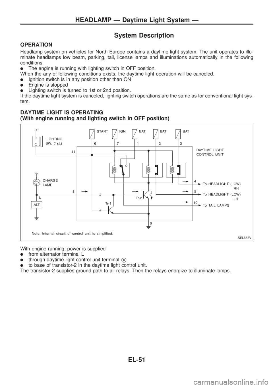
DAYTIME LIGHT IS OPERATING
(With engine running and lighting switch in OFF position)
With engine running, power is supplied
lfrom alternator terminal L
lthrough daytime light control unit terminalV8
lto base of transistor-2 in the daytime light control unit.
The transistor-2 supplies ground path to all relays. Then the relays energize to illuminate lamps.
SEL667V
HEADLAMP Ð Daytime Light System Ð
EL-51
Page 1361 of 1659
![NISSAN PICK-UP 1998 Repair Manual System Description
CIRCUIT OPERATION
[Example]
Aiming switch ``0
lWhen the aiming switch is set to ``0, the motor will not start.
This is because the power terminals are positioned at the
noncondu NISSAN PICK-UP 1998 Repair Manual System Description
CIRCUIT OPERATION
[Example]
Aiming switch ``0
lWhen the aiming switch is set to ``0, the motor will not start.
This is because the power terminals are positioned at the
noncondu](/manual-img/5/57374/w960_57374-1360.png)
System Description
CIRCUIT OPERATION
[Example]
Aiming switch ``0''
lWhen the aiming switch is set to ``0'', the motor will not start.
This is because the power terminals are positioned at the
nonconductive section of the sensor's rotary unit.
Aiming switch ``0''®``1''
lWhen the aiming switch is moved from ``0'' to ``1'', the sen-
sor's conductive section activates the relay. Power is sup-
plied through the relay to the motor. The headlamps will then
move in the ``DOWN'' direction.
lThe motor continues to rotate while the rotary unit of the
sensor moves from point A to point B.
lThe power terminals will then be positioned at the noncon-
ductive section, disconnecting the power to the motor. The
motor will then stop.
Aiming switch ``1''®``0''
lWhen the aiming switch is moved from ``1'' to ``0'', the sen-
sor's conductive section activates the relay. Power is sup-
plied through the relay to the motor. The motor will rotate to
move the headlamps in the ``UP'' direction.
lWhen the rotary unit of the sensor moves from point B to
point A, the motor will stop.
SEL465M
SEL364P
SEL365P
HEADLAMP Ð Headlamp Aiming Control Ð
EL-63