1998 NISSAN PICK-UP relay
[x] Cancel search: relayPage 869 of 1659
Radiator (KA24 engine) ................................. LC-9
Radiator (TD25 engine) ............................... LC-24
Rear axle ....................................................... RA-5
Rear body..................................................... BT-40
Rear case (Transfer) ...................................... TF-8
Rear combination lamp removal and
installation................................................. BT-24
Rear cover gasket replacement diff. ........... PD-13
Rear door ..................................................... BT-11
Rear drum brake.......................................... BR-26
Rear fog lamp............................................... EL-72
Rear seat belt ................................................ RS-4
Rear seat...................................................... BT-33
Rear suspension .......................................... RA-12
Rear window defogger ............................... EL-135
Refrigerant connection precaution................. HA-2
Refrigerant discharging evacuating
charging ................................................... HA-49
Refrigerant general precaution ...................... HA-2
Refrigerant lines........................................... HA-52
Refrigeration cycle ....................................... HA-12
Release bearing (clutch) ................................ CL-9
Removal and installation (Transfer) ............... TF-6
Resistor ...................................................... EC-105
Reverse idler shaft (M/T) (FS5R30A) ......... MT-36
Reverse idler shaft (M/T) (FS5W71C) ........ MT-15
Reverse lamp switch (M/T) - See
Back-up lamp switch (M/T) ........................ MT-9
Reverse main gear (M/T) (FS5R30A) ......... MT-36
Reverse main gear (M/T) (FS5W71C) ........ MT-15
Ring gear diff. inspection (C200)................. PD-38
Ring gear diff. inspection (H233B) .............. PD-60
Road wheel size ........................................... GI-46
Roof trim....................................................... BT-21
Room lamp - See Interior lamp.................... EL-85
Rotor disc (front) .......................................... FA-16
S
S/SIG - Wiring diagram...............................EC-149
SAE J1930 terminology list........................... GI-55
SMJ (super multiple junction) .................... Foldout
SRS - See Supplemental Restraint
System ....................................................... RS-6
SRS Trouble diagnoses
(2WD models) .......................................... RS-17
SRS Trouble diagnoses
(4WD models) .......................................... RS-22
START - Wiring diagram .............................. EL-26
SWL/V - Wiring diagram ............................ EC-163
Screw jack..................................................... GI-48
Seal - See Exterior....................................... BT-24
Seat belt inspection ..................................... MA-40
Seat belt, front ............................................... RS-3
Seat belt, rear ................................................ RS-4
Seat, front..................................................... BT-30
Seat, rear ..................................................... BT-33
Self-diagnostic results.................................. EC-38
Shift control (Transfer) ................................. TF-10Shift control components (M/T)
(FS5R30A) ................................................MT-38
Shift control components (M/T)
(FS5W71C) .............................................. MT-17
Shift fork (M/T) (FS5R30A) ......................... MT-38
Shift fork (M/T) (FS5W71C) ........................ MT-17
Shift lever (FS5R30A) ................................. MT-38
Shift lever (FS5W71C) ................................ MT-17
Shock absorber (front) ................................. FA-28
Shock absorber (rear).................................. RA-13
Side bearing preload (R180A) ..................... PD-23
Side bearing preload (C200) ....................... PD-45
Side trim ....................................................... BT-15
Side window ................................................. BT-38
Spark plug replacement .............................. MA-20
Spiral cable .................................................. RS-11
Spot lamp ..................................................... EL-85
Stabilizer bar (front) ..................................... FA-31
Standardized relay ......................................... EL-3
Start signal ................................................. EC-149
Starter ........................................................... EL-33
Starting system............................................. EL-26
Steering gear and linkage inspection.......... MA-37
Steering gear oil level ................................. MA-38
Steering knuckle........................................... FA-18
Steering linkage ........................................... ST-37
Steering wheel and column ........................... ST-9
Steering wheel play........................................ ST-6
Steering wheel turning force .......................... ST-6
Striking rod (M/T) (FS5R30A) ..................... MT-38
Striking rod (M/T) (FS5W71C) .................... MT-17
Sub-gear (M/T) (FS5R30A) ......................... MT-36
Sub-gear (M/T) (FS5W71C) ........................ MT-15
Sunroof ......................................................... BT-35
Supplemental Restraint System .................... RS-6
Supplemental restraint system - Wiring
diagram (2WD models) ............................ RS-18
Supplemental restraint system - Wiring
diagram (4WD models) ............................ RS-26
Swirl control valve control solenoid
valve ....................................................... EC-161
Symbols and abbreviations............................. GI-8
Synchronizer (M/T) (FS5R30A) ................... MT-36
Synchronizer (M/T) (FS5W71C) .................. MT-15
T
TAIL/L - Wiring diagram ................................EL-66
TPS - Wiring diagram ................................ EC-115
TURN - Wiring diagram................................ EL-75
Tail lamp ....................................................... EL-66
Temperature control cable and linkage
adjustment................................................ HA-47
Tension rod (front) ....................................... FA-33
Thermal protector ........................................ HA-45
Thermo control amp .................................... HA-44
Thermostat (KA24 engine) ............................. LC-8
Thermostat (TD25 engine) ........................... LC-23
Three way catalyst precautions ...................... GI-4
ALPHABETICAL INDEX
IDX-7
Page 891 of 1659
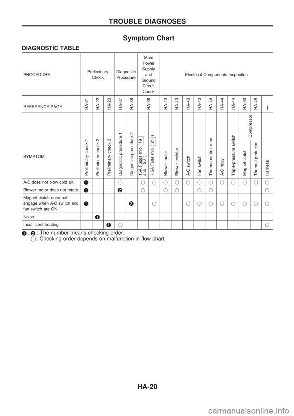
Symptom Chart
DIAGNOSTIC TABLE
PROCEDUREPreliminary
CheckDiagnostic
ProcedureMain
Power
Supply
and
Ground
Circuit
CheckElectrical Components Inspection
REFERENCE PAGE
HA-21
HA-22
HA-23
HA-37
HA-39
HA-36
HA-43
HA-43
HA-43
HA-43
HA-44
HA-44
HA-44
HA-60
HA-45
Ð
SYMPTOM
Preliminary check 1
Preliminary check 2
Preliminary check 3
Diagnostic procedure 1
Diagnostic procedure 2
15A Fuses (No.
19
and
20 )
7.5A Fuse (No.
21 )
Blower motor
Blower resistor
A/C switch
Fan switch
Thermo control amp.
A/C relay
Triple-pressure switch
Compressor
Harness Magnet clutch
Thermal protector
A/C does not blow cold air.j jjjjjjjjjjjj
Blower motor does not rotate.
jjjjj j
Magnet clutch does not
engage when A/C switch and
fan switch are ON.
j jjjjjjjj
Noise.
Insufficient heating.jj
,: The number means checking order.
j: Checking order depends on malfunction in flow chart.
TROUBLE DIAGNOSES
HA-20
Page 910 of 1659

Diagnostic Procedure 2
EXCEPT FOR KA ENGINE MODELS
SYMPTOM: Magnet clutch does not engage when A/C
switch and fan switch are ON.
lPerform PRELIMINARY CHECK 1 before referring to the
following flow chart.
CHECK POWER SUPPLY FOR COM-
PRESSOR.
Disconnect compressor harness connec-
tor.
Do approx. 12 volts exist between com-
pressor harness terminal No.
V1and body
ground?
No
cYes
Check the following.
lMagnet clutch coillThermal protector (Except
for the Middle East)
NG
Replace magnet clutch.
Refer to HA-60.
Note
Check circuit continuity between A/C relay
harness terminal No.
V5and compressor
harness terminal No.
V1.
Continuity should exist.
If OK, check harness for short.
OK
CHECK POWER SUPPLY FOR A/C
RELAY.
Do approx. 12 volts exist between A/C
relay harness terminal No.
V3and body
ground?
Yes
cNo
Check power supply circuit
and 7.5A fuse (No.
21 ,
located in the fuse block).
(Refer to ``POWER SUP-
PLY ROUTING'' in EL sec-
tion and Wiring Diagram.)
CHECK POWER SUPPLY FOR A/C
RELAY.
Do approx. 12 volts exist between A/C
relay harness terminal No.
V1and body
ground?
No
cYes
Check power supply circuit
and 7.5A fuse (No.
21 ,
located in the fuse block).
(Refer to ``POWER SUP-
PLY ROUTING'' in EL sec-
tion and Wiring Diagram.)
CHECK A/C RELAY AFTER DISCON-
NECTING IT.
Refer to HA-44.
OK
cNG
Replace A/C relay.
Reconnect A/C relay.
Note
Check circuit continuity between A/C relay
harness terminal No.
V2and triple-pres-
sure switch harness terminal No.
V4.
Continuity should exist.
If OK, check harness for short.
OK
VA(Go to next page.)
Note:
If the result is NG after checking circuit continuity, repair harness or con-
nector.
RHA325G
RHA748FD
RHA359G
RHA375G
RHA327GA
.
.
.
.
.
.
.
.
TROUBLE DIAGNOSES
HA-39
Page 912 of 1659

FOR KA ENGINE MODELS
SYMPTOM: Magnet clutch does not engage when A/C
switch and fan switch are ON.
lPerform PRELIMINARY CHECK 1 before referring to the
following flow chart.
CHECK POWER SUPPLY FOR COM-
PRESSOR.
Disconnect compressor harness connec-
tor.
Do approx. 12 volts exist between com-
pressor harness terminal No.
V1and body
ground?
No
cYes
Check the following.
lMagnet clutch coil
lThermal protector
NG
Replace magnet clutch.
Refer to HA-60.
Note
Check circuit continuity between A/C relay
harness terminal No.
V5and compressor
harness terminal No.
V1.
Continuity should exist.
If OK, check harness for short.
OK
CHECK POWER SUPPLY FOR A/C
RELAY.
Do approx. 12 volts exist between A/C
relay harness terminal No.
V3and body
ground?
Yes
cNo
Check power supply circuit
and 7.5A fuse (No.
21 ,
located in the fuse block).
(Refer to ``POWER SUP-
PLY ROUTING'' in EL sec-
tion and Wiring Diagram.)
CHECK POWER SUPPLY FOR A/C
RELAY.
Do approx. 12 volts exist between A/C
relay harness terminal No.
V1and body
ground?
Yes
cNo
Check power supply circuit
and 7.5A fuse (No.
21 ,
located in the fuse block).
(Refer to ``POWER SUP-
PLY ROUTING'' in EL sec-
tion and Wiring Diagram.)
CHECK A/C RELAY AFTER DISCON-
NECTING IT.
Refer to HA-44.
OK
cNG
Replace A/C relay.
Reconnect A/C relay.
VA
(Go to next page.)
Note:
If the result is NG after checking circuit continuity, repair harness or con-
nector.
RHA333G
RHA334G
RHA359G
RHA375G
.
.
.
.
.
.
.
TROUBLE DIAGNOSES
Diagnostic Procedure 2 (Cont'd)
HA-41
Page 913 of 1659
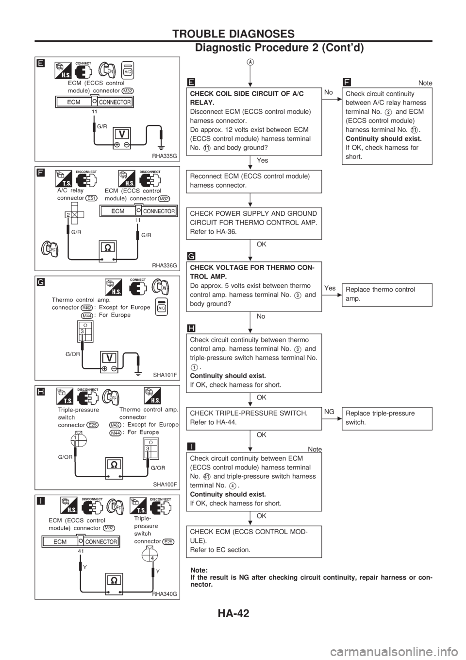
VA
Note
CHECK COIL SIDE CIRCUIT OF A/C
RELAY.
Disconnect ECM (ECCS control module)
harness connector.
Do approx. 12 volts exist between ECM
(ECCS control module) harness terminal
No.
V11and body ground?
Yes
cNo
Check circuit continuity
between A/C relay harness
terminal No.
V2and ECM
(ECCS control module)
harness terminal No.
V11.
Continuity should exist.
If OK, check harness for
short.
Reconnect ECM (ECCS control module)
harness connector.
CHECK POWER SUPPLY AND GROUND
CIRCUIT FOR THERMO CONTROL AMP.
Refer to HA-36.
OK
CHECK VOLTAGE FOR THERMO CON-
TROL AMP.
Do approx. 5 volts exist between thermo
control amp. harness terminal No.
V3and
body ground?
No
cYes
Replace thermo control
amp.
Check circuit continuity between thermo
control amp. harness terminal No.
V3and
triple-pressure switch harness terminal No.
V1.
Continuity should exist.
If OK, check harness for short.
OK
CHECK TRIPLE-PRESSURE SWITCH.
Refer to HA-44.
OK
cNG
Replace triple-pressure
switch.
Note
Check circuit continuity between ECM
(ECCS control module) harness terminal
No.
V41and triple-pressure switch harness
terminal No.
V4.
Continuity should exist.
If OK, check harness for short.
OK
CHECK ECM (ECCS CONTROL MOD-
ULE).
Refer to EC section.
Note:
If the result is NG after checking circuit continuity, repair harness or con-
nector.
RHA335G
RHA336G
SHA101F
SHA100F
RHA340G
.
.
.
.
.
.
.
.
TROUBLE DIAGNOSES
Diagnostic Procedure 2 (Cont'd)
HA-42
Page 915 of 1659
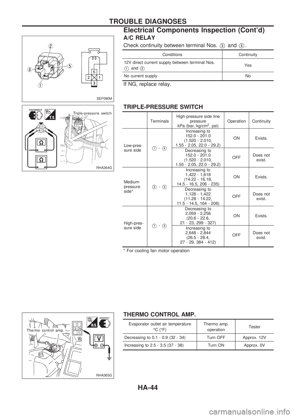
A/C RELAY
Check continuity between terminal Nos.V3andV5.
Conditions Continuity
12V direct current supply between terminal Nos.
V1andV2Yes
No current supply No
If NG, replace relay.
TRIPLE-PRESSURE SWITCH
TerminalsHigh-pressure side line
pressure
kPa (bar, kg/cm2, psi)Operation Continuity
Low-pres-
sure side
V1-V4
Increasing to
152.0 - 201.0
(1.520 - 2.010,
1.55 - 2.05, 22.0 - 29.2)ON Exists.
Decreasing to
152.0 - 201.0
(1.520 - 2.010,
1.55 - 2.05, 22.0 - 29.2)OFFDoes not
exist.
Medium-
pressure
side*
V2-V3
Increasing to
1,422 - 1,618
(14.22 - 16.18,
14.5 - 16.5, 206 - 235)ON Exists.
Decreasing to
1,128 - 1,422
(11.28 - 14.22,
11.5 - 14.5, 164 - 206)OFFDoes not
exist.
High-pres-
sure side
V1-V4
Decreasing to
2,059 - 2,256
(20.6 - 22.6,
21 - 23, 299 - 327)ON Exists.
Increasing to
2,648 - 2,844
(26.5 - 28.4,
27 - 29, 384 - 412)OFFDoes not
exist.
* For cooling fan motor operation
THERMO CONTROL AMP.
Evaporator outlet air temperature
ÉC (ÉF)Thermo amp.
operationTester
Decreasing to 0.1 - 0.9 (32 - 34) Turn OFF Approx. 12V
Increasing to 2.5 - 3.5 (37 - 38) Turn ON Approx. 0V
SEF090M
RHA364G
RHA365G
TROUBLE DIAGNOSES
Electrical Components Inspection (Cont'd)
HA-44
Page 965 of 1659
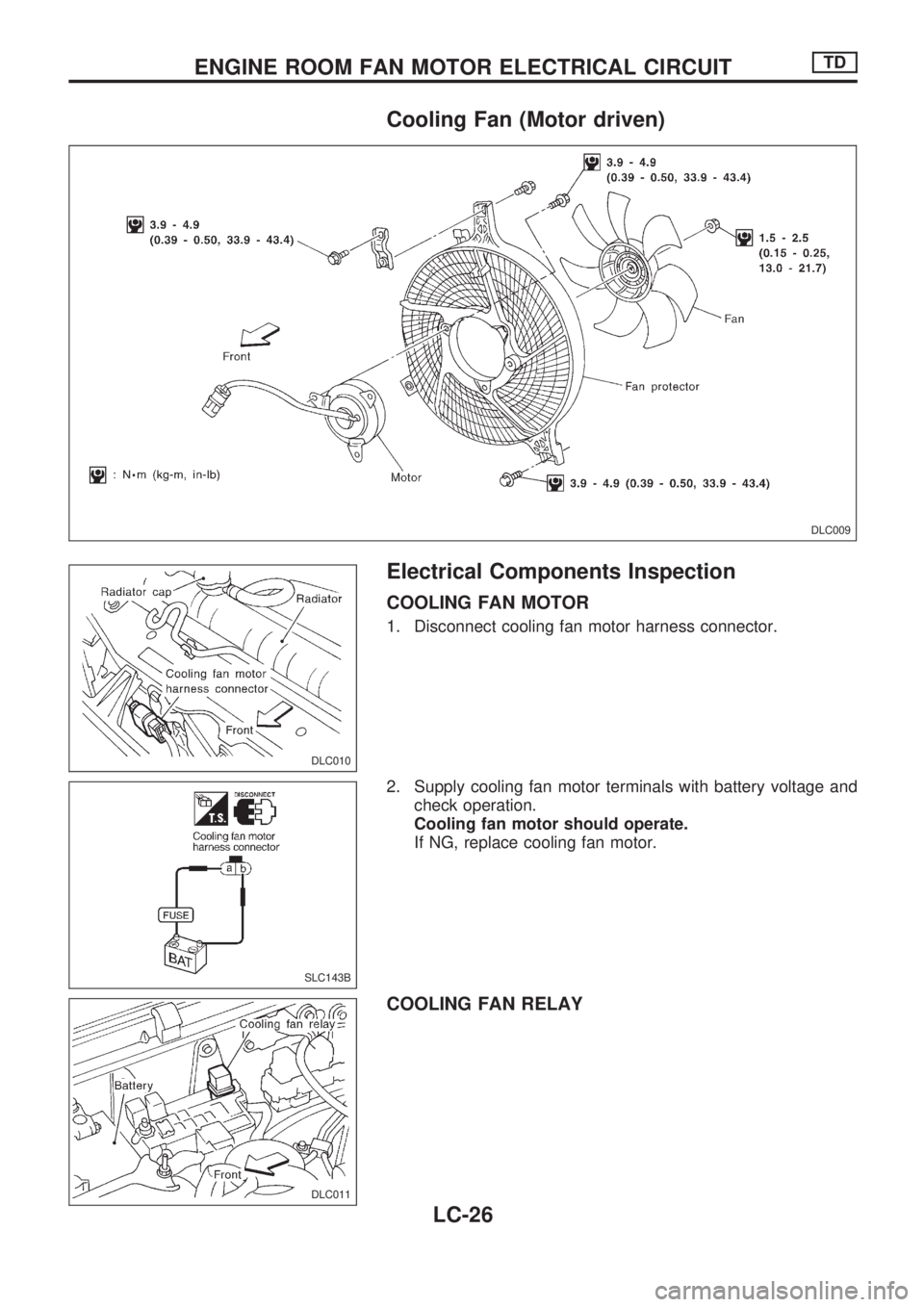
Cooling Fan (Motor driven)
Electrical Components Inspection
COOLING FAN MOTOR
1. Disconnect cooling fan motor harness connector.
2. Supply cooling fan motor terminals with battery voltage and
check operation.
Cooling fan motor should operate.
If NG, replace cooling fan motor.
COOLING FAN RELAY
DLC009
DLC010
SLC143B
DLC011
ENGINE ROOM FAN MOTOR ELECTRICAL CIRCUITTD
LC-26
Page 966 of 1659
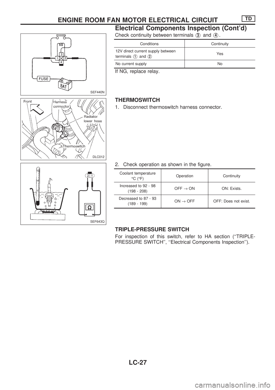
Check continuity between terminalsV3andV4.
Conditions Continuity
12V direct current supply between
terminals
V1andV2Yes
No current supply No
If NG, replace relay.
THERMOSWITCH
1. Disconnect thermoswitch harness connector.
2. Check operation as shown in the figure.
Coolant temperature
ÉC (ÉF)Operation Continuity
Increased to 92 - 98
(198 - 208)OFF®ON ON: Exists.
Decreased to 87 - 93
(189 - 199)ON®OFF OFF: Does not exist.
TRIPLE-PRESSURE SWITCH
For inspection of this switch, refer to HA section (``TRIPLE-
PRESSURE SWITCH'', ``Electrical Components Inspection'').
SEF440N
DLC012
SEF643Q
ENGINE ROOM FAN MOTOR ELECTRICAL CIRCUITTD
Electrical Components Inspection (Cont'd)
LC-27