Page 1604 of 1659
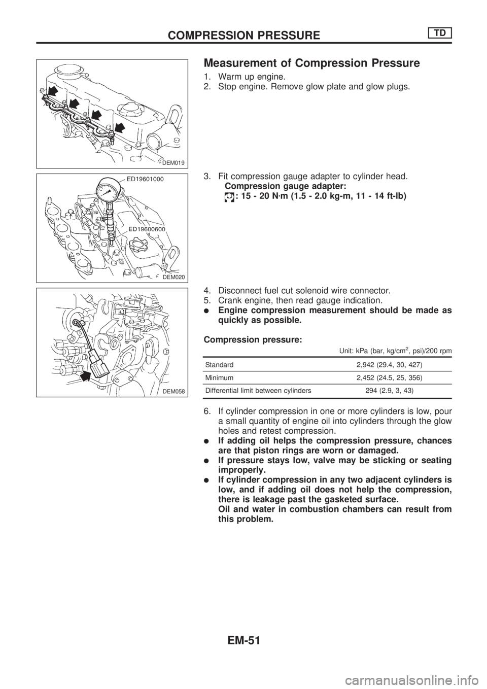
Measurement of Compression Pressure
1. Warm up engine.
2. Stop engine. Remove glow plate and glow plugs.
3. Fit compression gauge adapter to cylinder head.
Compression gauge adapter:
:15-20Nzm (1.5 - 2.0 kg-m, 11 - 14 ft-lb)
4. Disconnect fuel cut solenoid wire connector.
5. Crank engine, then read gauge indication.
lEngine compression measurement should be made as
quickly as possible.
Compression pressure:
Unit: kPa (bar, kg/cm2, psi)/200 rpm
Standard 2,942 (29.4, 30, 427)
Minimum 2,452 (24.5, 25, 356)
Differential limit between cylinders 294 (2.9, 3, 43)
6. If cylinder compression in one or more cylinders is low, pour
a small quantity of engine oil into cylinders through the glow
holes and retest compression.
lIf adding oil helps the compression pressure, chances
are that piston rings are worn or damaged.
lIf pressure stays low, valve may be sticking or seating
improperly.
lIf cylinder compression in any two adjacent cylinders is
low, and if adding oil does not help the compression,
there is leakage past the gasketed surface.
Oil and water in combustion chambers can result from
this problem.
DEM019.DEM019
DEM020
DEM058
COMPRESSION PRESSURETD
EM-51
Page 1605 of 1659
Removal
Removal order and pointsApplied model
2WD 4WD
1 Remove undercover.jj
2 Drain engine oil.jj
3Remove front propeller shaft
from front differential carrier.Ðj
4Remove front drive shaft fix-
ing bolts (RH & LH).Ðj
5Remove front suspension
crossmember.jj
6Remove differential front
mounting bolts (RH & LH)
and rear mounting bolts.Ðj
7Remove front differential car-
rier.ÐjRemoval order and pointsApplied model
2WD 4WD
8Remove front differential car-
rier mounting bracket.Ðj
9Remove transmission to rear
engine mounting bracket
nuts (RH & LH).jj
10Remove engine mounting
bolts or nuts (RH & LH).jj
11Lift up engine.
If necessary, disconnect
exhaust tube.jj
12 Remove oil pan.jj
WARNING:
lPlace vehicle on a flat and solid surface.
lPlace chocks at front and rear of rear wheels.
lYou should not remove oil pan until exhaust system and
cooling system have completely cooled off.
Otherwise, you may burn yourself and/or fire may break
out in the fuel line.
lWhen removing front and/or rear engine mounting bolts
or nuts, lift up slightly engine for safety work.
CAUTION:
lIn lifting engine, be careful not to hit against adjacent
parts, especially against accelerator wire casing end,
brake tube and brake master cylinder.
lFor tightening torque, refer to EM-71, MT and PD sec-
tions.
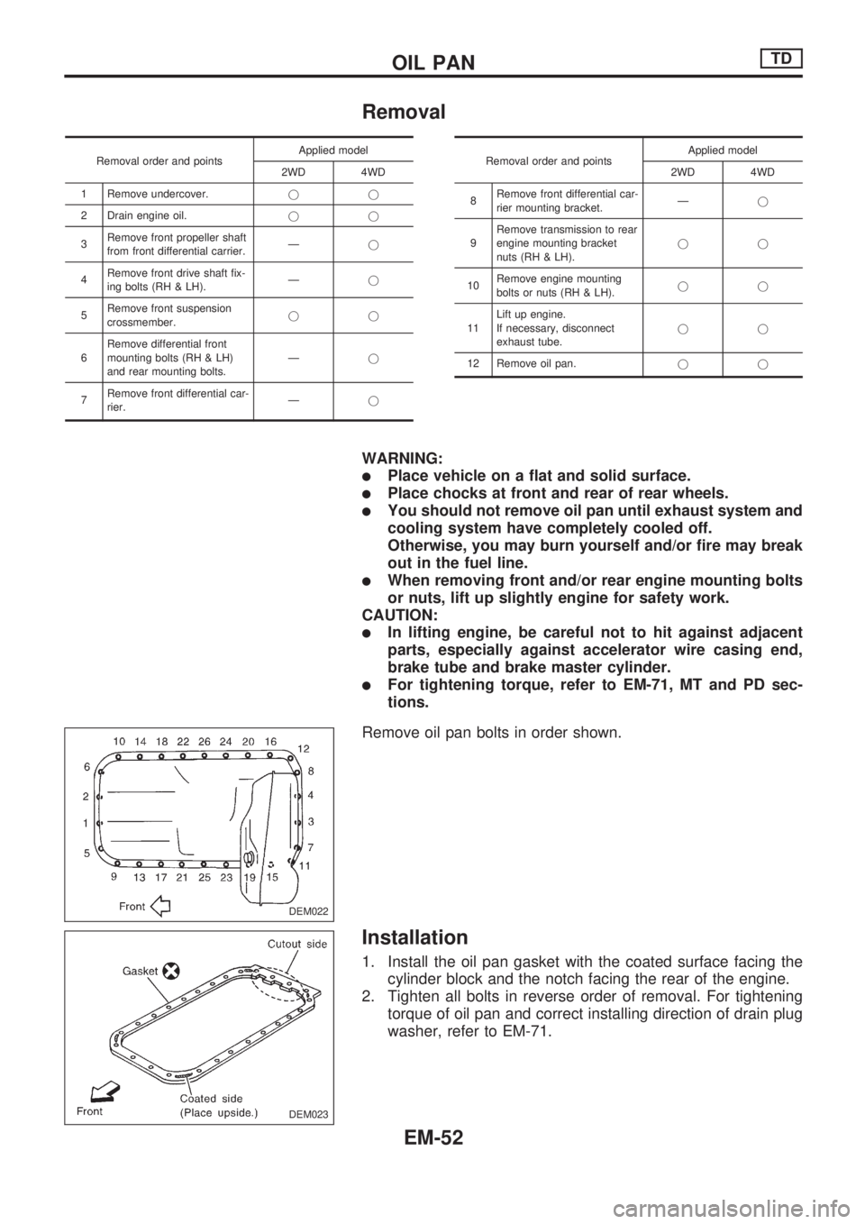
Remove oil pan bolts in order shown.
Installation
1. Install the oil pan gasket with the coated surface facing the
cylinder block and the notch facing the rear of the engine.
2. Tighten all bolts in reverse order of removal. For tightening
torque of oil pan and correct installing direction of drain plug
washer, refer to EM-71.
DEM022
DEM023
OIL PANTD
EM-52
Page 1607 of 1659
CAUTION:
lWhen installing sliding parts such as rocker arms, cam-
shaft and oil seal, be sure to apply new engine oil on
their sliding surfaces.
lWhen tightening cylinder head bolts and rocker shaft
bolts, apply new engine oil to thread portions and seat
surfaces of bolts.
Removal
1. Set No. 1 cylinder at TDC (top dead center) on its compres-
sion stroke.
2. Drain engine coolant from drain plugs on cylinder block and
radiator.
3. Remove air cleaner and/or air duct.
4. Remove alternator adjusting bolt.
5. Disconnect exhaust manifold from front exhaust tube.
6. Disconnect radiator outlet hose and thermostat housing
water inlet hose.
7. Remove air intake housing.
8. Remove fuel injection tube assembly and spill tube.
9. Remove injection nozzle holder and top nozzle gasket using
deep socket wrench.
MEM125A
DEM024
DEM025
DEM026
CYLINDER HEADTD
EM-54
Page 1608 of 1659
10. Remove rocker cover.
11. Remove rocker shaft with rocker arms.
12. Remove push rods.
13. Remove cylinder head bolts in numerical order and remove
cylinder head.
Head warpage or cracking could result from removing in
incorrect order.
Disassembly
1. Remove following parts:
a. Intake manifold
b. Exhaust manifold
c. Thermostat housing
d. Alternator adjusting bar & engine slinger
e. Glow plate and glow plugs
2. Remove valve component parts with Tool.
SEM607F
DEM028
SEM623B
SEM624B
DEM029-A
CYLINDER HEADTD
Removal (Cont'd)
EM-55
Page 1612 of 1659
7. Cut or grind valve seat using suitable tool at the specified
dimensions as shown in SDS, EM-100.
8. After cutting, lap valve seat with a lapping compound.
9. Check contact condition of valve seat.
COMBUSTION CHAMBER
Check combustion chamber for cracks and other damage. If
necessary, replace.
REPLACING COMBUSTION CHAMBER
Usually combustion chamber should not be removed.
1. Remove combustion chamber so that cylinder head cannot
be damaged.
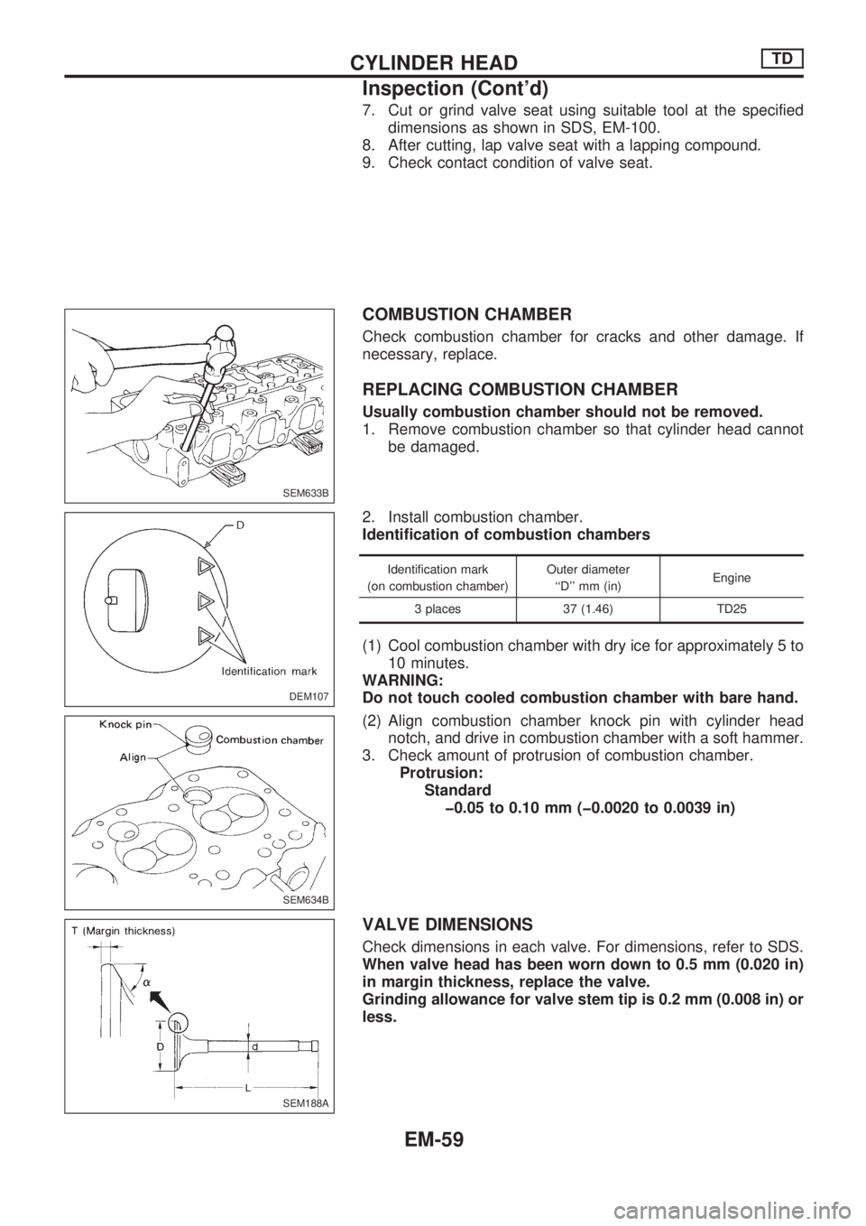
2. Install combustion chamber.
Identification of combustion chambers
Identification mark
(on combustion chamber)Outer diameter
``D'' mm (in)Engine
3 places 37 (1.46) TD25
(1) Cool combustion chamber with dry ice for approximately 5 to
10 minutes.
WARNING:
Do not touch cooled combustion chamber with bare hand.
(2) Align combustion chamber knock pin with cylinder head
notch, and drive in combustion chamber with a soft hammer.
3. Check amount of protrusion of combustion chamber.
Protrusion:
Standard
þ0.05 to 0.10 mm (þ0.0020 to 0.0039 in)
VALVE DIMENSIONS
Check dimensions in each valve. For dimensions, refer to SDS.
When valve head has been worn down to 0.5 mm (0.020 in)
in margin thickness, replace the valve.
Grinding allowance for valve stem tip is 0.2 mm (0.008 in) or
less.
SEM633B
DEM107
.
SEM634B
SEM188A
CYLINDER HEADTD
Inspection (Cont'd)
EM-59
Page 1615 of 1659
Assembly
1. Assemble rocker shaft component parts.
lFace punch mark toward the front of the engine.
Identification of rocker arms
Identification mark
(At area
Vaon rocker arm)For use with
Two ridges Intake
No ridge Exhaust
2. Install valve component parts.
Identification of valves
Identification mark
(on intake and exhaust valve)
Engine
Intake valve Exhaust valve
2 B TD25
lAlways use new valve oil seal. (Refer to EM-68.)
lInstall valve spring (uneven pitch type) with its narrow
pitch side toward cylinder head side.
DEM034
SEM066C
MEM180A
SEM615F
SEM638B
CYLINDER HEADTD
EM-62
Page 1616 of 1659
Installation
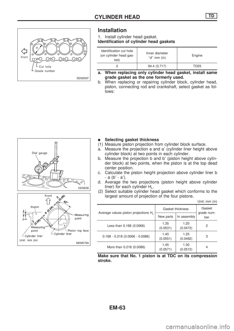
1. Install cylinder head gasket.
Identification of cylinder head gaskets
Identification cut hole
(on cylinder head gas-
ket)Inner diameter
``d'' mm (in)Engine
2 94.4 (3.717) TD25
a. When replacing only cylinder head gasket, install same
grade gasket as the one formerly used.
b. When replacing or repairing cylinder block, cylinder head,
piston, connecting rod and crankshaft, select gasket as fol-
lows:
lSelecting gasket thickness
(1) Measure piston projection from cylinder block surface.
a. Measure the projection a and a¢(cylinder liner height above
cylinder block) at two points in each cylinder.
b. Measure the projection b and b¢(piston height above cylin-
der block) at two points, when the piston is at the top dead
center position.
c. Calculate the piston height projection above cylinder liner b
-a(b¢-a¢).
d. Average the two projections (piston height above cylinder
liner) for each cylinder H
L.
(2) Select suitable cylinder head gasket which conforms to the
largest amount of projection of the four pistons.
Unit: mm (in)
Average values piston projections HL
Gasket thicknessGasket
grade num-
ber New parts In assembly
Less than 0.168 (0.0066)1.35
(0.0531)1.20
(0.0472)2
0.168 - 0.218 (0.0066 - 0.0086)1.40
(0.0551)1.25
(0.0492)3
More than 0.218 (0.0086)1.45
(0.0571)1.30
(0.0512)4
Make sure that No. 1 piston is at TDC on its compression
stroke.
SEM250F
.
DEM036
MEM079A
CYLINDER HEADTD
EM-63
Page 1617 of 1659
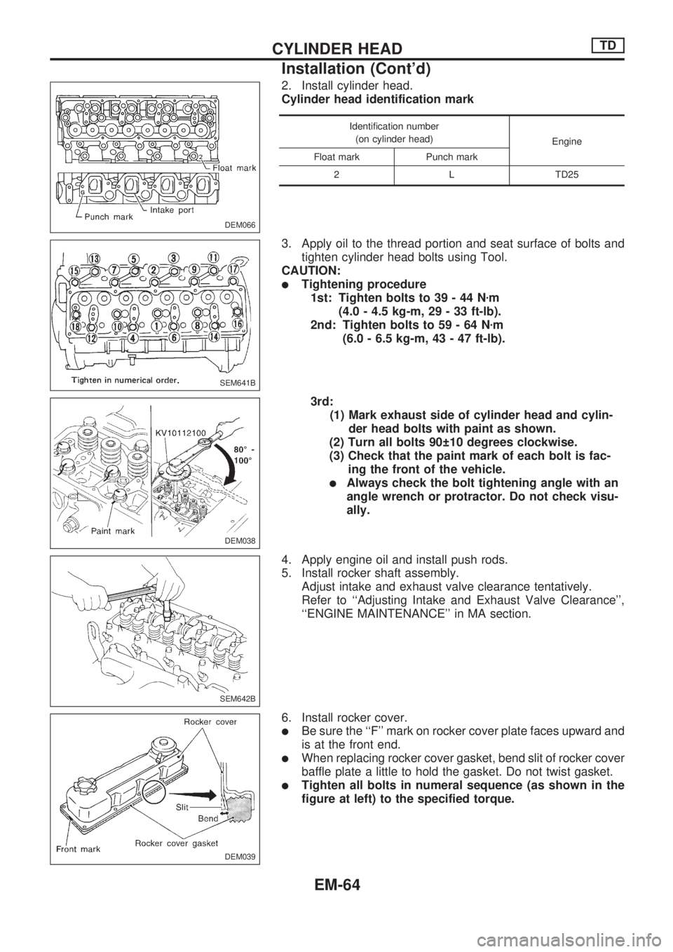
2. Install cylinder head.
Cylinder head identification mark
Identification number
(on cylinder head)
Engine
Float mark Punch mark
2 L TD25
3. Apply oil to the thread portion and seat surface of bolts and
tighten cylinder head bolts using Tool.
CAUTION:
lTightening procedure
1st: Tighten bolts to 39 - 44 Nzm
(4.0 - 4.5 kg-m, 29 - 33 ft-lb).
2nd: Tighten bolts to 59 - 64 Nzm
(6.0 - 6.5 kg-m, 43 - 47 ft-lb).
3rd:
(1) Mark exhaust side of cylinder head and cylin-
der head bolts with paint as shown.
(2) Turn all bolts 90 10 degrees clockwise.
(3) Check that the paint mark of each bolt is fac-
ing the front of the vehicle.
lAlways check the bolt tightening angle with an
angle wrench or protractor. Do not check visu-
ally.
4. Apply engine oil and install push rods.
5. Install rocker shaft assembly.
Adjust intake and exhaust valve clearance tentatively.
Refer to ``Adjusting Intake and Exhaust Valve Clearance'',
``ENGINE MAINTENANCE'' in MA section.
6. Install rocker cover.
lBe sure the ``F'' mark on rocker cover plate faces upward and
is at the front end.
lWhen replacing rocker cover gasket, bend slit of rocker cover
baffle plate a little to hold the gasket. Do not twist gasket.
lTighten all bolts in numeral sequence (as shown in the
figure at left) to the specified torque.
DEM066
SEM641B
DEM038
SEM642B
DEM039
CYLINDER HEADTD
Installation (Cont'd)
EM-64