Page 680 of 1659
3. Set chain on camshaft sprocket by aligning each mating
mark. Then install camshaft sprocket to camshaft.
4. Tighten camshaft sprocket bolt.
5. Install rubber plugs. Refer to TIMING CHAIN, EM-21.
6. Check hydraulic valve lifter.
a. Push hydraulic valve lifter forcefully with your finger.
lBe sure to check it with rocker arm in its free position.
b. If valve lifter moves more than 1 mm (0.04 in), air may be
inside of it.
c. Bleed air off by running engine at 1,000 rpm under no-load
for about 20 minutes.
d. If hydraulic valve lifters are still noisy, replace them and bleed
air off again in the same manner as in step c.
7. Install rocker cover. Refer to TIMING CHAIN, EM-21.
lBe sure to avoid interference between rocker cover and
rocker arm.
8. Install intake and exhaust manifolds. Refer to ``OUTER COM-
PONENT PARTS'', EM-9.
SEM612F
SEM592F
SEM275C
CYLINDER HEADKA
Installation (Cont'd)
EM-35
Page 681 of 1659
WARNING:
lPosition vehicle on a flat and solid surface.
lPlace chocks at front and back of rear wheels.
lDo not remove engine until exhaust system has com-
pletely cooled off.
Otherwise, you may burn yourself and/or fire may break
out in fuel line.
lBefore disconnecting fuel hose, release fuel pressure.
Refer to EC section (``Fuel Pressure Release'').
lBe sure to hoist engine and transmission in a safe man-
ner.
lFor engines not equipped with engine slingers, attach
proper slingers and bolts described in PARTS CATA-
LOG.
CAUTION:
lWhen lifting engine, be sure to clear surrounding parts.
Take special care near accelerator wire casing, brake
lines and brake master cylinder.
lIn lifting the engine, always use engine slingers in a safe
manner.
lFor 4WD models, apply sealant between engine and
transmission. Refer to MT section (``Removal and Instal-
lation'').
SEM601FA
ENGINE REMOVALKA
EM-36
Page 682 of 1659
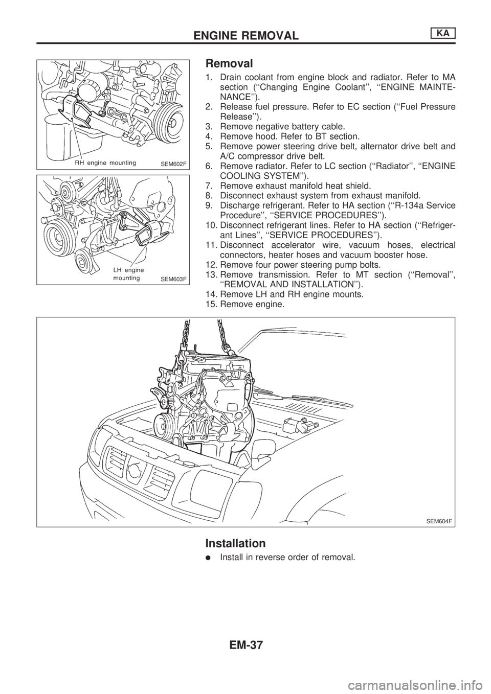
Removal
1. Drain coolant from engine block and radiator. Refer to MA
section (``Changing Engine Coolant'', ``ENGINE MAINTE-
NANCE'').
2. Release fuel pressure. Refer to EC section (``Fuel Pressure
Release'').
3. Remove negative battery cable.
4. Remove hood. Refer to BT section.
5. Remove power steering drive belt, alternator drive belt and
A/C compressor drive belt.
6. Remove radiator. Refer to LC section (``Radiator'', ``ENGINE
COOLING SYSTEM'').
7. Remove exhaust manifold heat shield.
8. Disconnect exhaust system from exhaust manifold.
9. Discharge refrigerant. Refer to HA section (``R-134a Service
Procedure'', ``SERVICE PROCEDURES'').
10. Disconnect refrigerant lines. Refer to HA section (``Refriger-
ant Lines'', ``SERVICE PROCEDURES'').
11. Disconnect accelerator wire, vacuum hoses, electrical
connectors, heater hoses and vacuum booster hose.
12. Remove four power steering pump bolts.
13. Remove transmission. Refer to MT section (``Removal'',
``REMOVAL AND INSTALLATION'').
14. Remove LH and RH engine mounts.
15. Remove engine.
Installation
lInstall in reverse order of removal.
SEM602F
SEM603F
SEM604F
ENGINE REMOVALKA
EM-37
Page 684 of 1659
CAUTION:
lWhen installing sliding parts (bearings, pistons, etc.),
lubricate contacting surfaces with new engine oil.
lPlace removed parts such as bearings and bearing caps
in their proper order and direction.
lWhen installing connecting rod nuts and main bearing
cap bolts, apply new engine oil to threads and seating
surfaces.
lDo not allow any magnetic materials to contact the ring
gear teeth of flywheel or drive plate.
Disassembly
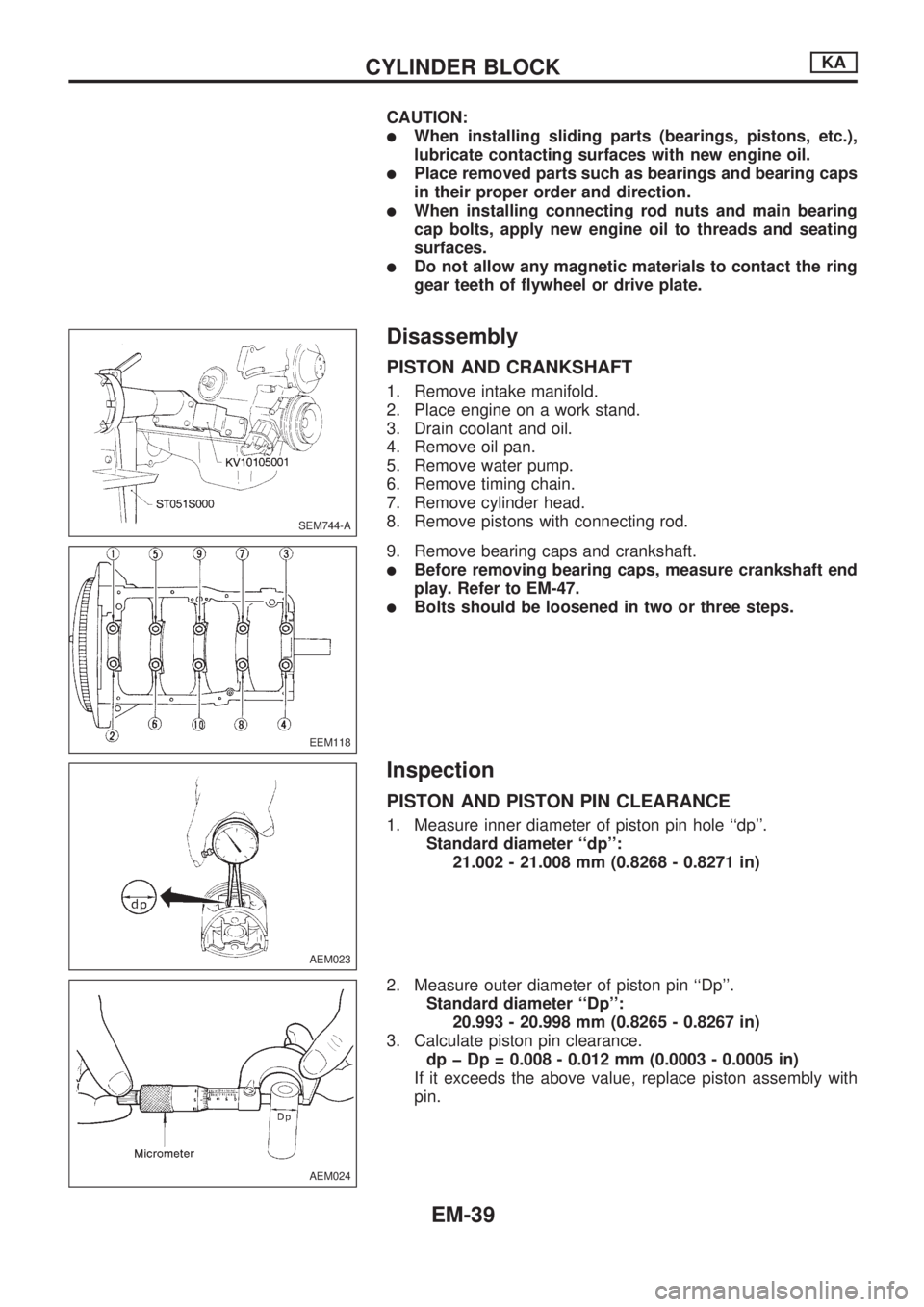
PISTON AND CRANKSHAFT
1. Remove intake manifold.
2. Place engine on a work stand.
3. Drain coolant and oil.
4. Remove oil pan.
5. Remove water pump.
6. Remove timing chain.
7. Remove cylinder head.
8. Remove pistons with connecting rod.
9. Remove bearing caps and crankshaft.
lBefore removing bearing caps, measure crankshaft end
play. Refer to EM-47.
lBolts should be loosened in two or three steps.
Inspection
PISTON AND PISTON PIN CLEARANCE
1. Measure inner diameter of piston pin hole ``dp''.
Standard diameter ``dp'':
21.002 - 21.008 mm (0.8268 - 0.8271 in)
2. Measure outer diameter of piston pin ``Dp''.
Standard diameter ``Dp'':
20.993 - 20.998 mm (0.8265 - 0.8267 in)
3. Calculate piston pin clearance.
dp þ Dp = 0.008 - 0.012 mm (0.0003 - 0.0005 in)
If it exceeds the above value, replace piston assembly with
pin.
SEM744-A
EEM118
AEM023
AEM024
CYLINDER BLOCKKA
EM-39
Page 691 of 1659
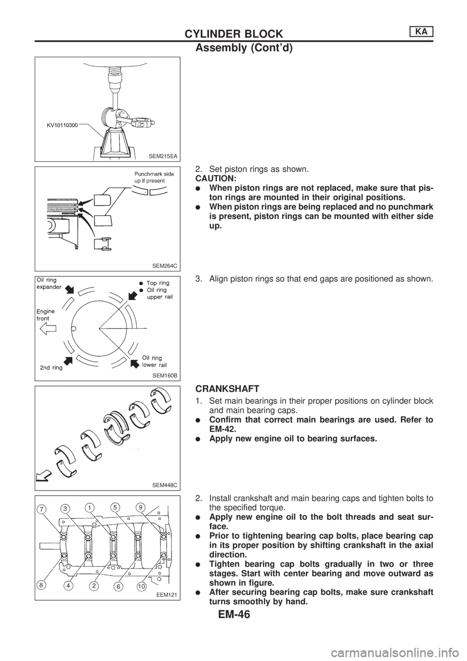
2. Set piston rings as shown.
CAUTION:
lWhen piston rings are not replaced, make sure that pis-
ton rings are mounted in their original positions.
lWhen piston rings are being replaced and no punchmark
is present, piston rings can be mounted with either side
up.
3. Align piston rings so that end gaps are positioned as shown.
CRANKSHAFT
1. Set main bearings in their proper positions on cylinder block
and main bearing caps.
lConfirm that correct main bearings are used. Refer to
EM-42.
lApply new engine oil to bearing surfaces.
2. Install crankshaft and main bearing caps and tighten bolts to
the specified torque.
lApply new engine oil to the bolt threads and seat sur-
face.
lPrior to tightening bearing cap bolts, place bearing cap
in its proper position by shifting crankshaft in the axial
direction.
lTighten bearing cap bolts gradually in two or three
stages. Start with center bearing and move outward as
shown in figure.
lAfter securing bearing cap bolts, make sure crankshaft
turns smoothly by hand.
SEM215EA
SEM264C
SEM160B
SEM448C
EEM121
CYLINDER BLOCKKA
Assembly (Cont'd)
EM-46
Page 692 of 1659
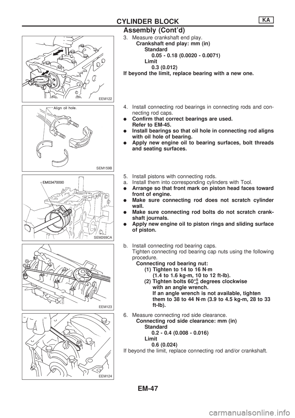
3. Measure crankshaft end play.
Crankshaft end play: mm (in)
Standard
0.05 - 0.18 (0.0020 - 0.0071)
Limit
0.3 (0.012)
If beyond the limit, replace bearing with a new one.
4. Install connecting rod bearings in connecting rods and con-
necting rod caps.
lConfirm that correct bearings are used.
Refer to EM-45.
lInstall bearings so that oil hole in connecting rod aligns
with oil hole of bearing.
lApply new engine oil to bearing surfaces, bolt threads
and seating surfaces.
5. Install pistons with connecting rods.
a. Install them into corresponding cylinders with Tool.
lArrange so that front mark on piston head faces toward
front of engine.
lMake sure connecting rod does not scratch cylinder
wall.
lMake sure connecting rod bolts do not scratch crank-
shaft journals.
lApply new engine oil to piston rings and sliding surface
of piston.
b. Install connecting rod bearing caps.
Tighten connecting rod bearing cap nuts using the following
procedure.
Connecting rod bearing nut:
(1) Tighten to 14 to 16 N´m
(1.4 to 1.6 kg-m, 10 to 12 ft-lb).
(2) Tighten bolts 60
+5
þ0degrees clockwise
with an angle wrench.
If an angle wrench is not available, tighten
them to 38 to 44 N´m (3.9 to 4.5 kg-m, 28 to 33
ft-lb).
6. Measure connecting rod side clearance.
Connecting rod side clearance: mm (in)
Standard
0.2 - 0.4 (0.008 - 0.016)
Limit
0.6 (0.024)
If beyond the limit, replace connecting rod and/or crankshaft.
EEM122
SEM159B
SEM269CA
EEM123
EEM124
CYLINDER BLOCKKA
Assembly (Cont'd)
EM-47
Page 696 of 1659
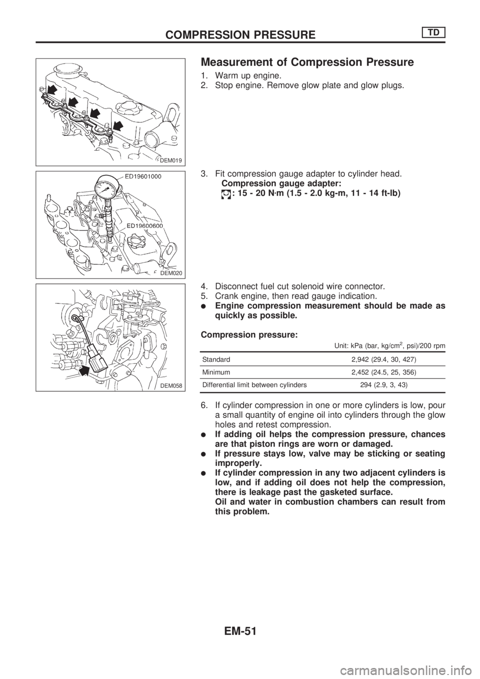
Measurement of Compression Pressure
1. Warm up engine.
2. Stop engine. Remove glow plate and glow plugs.
3. Fit compression gauge adapter to cylinder head.
Compression gauge adapter:
:15-20Nzm (1.5 - 2.0 kg-m, 11 - 14 ft-lb)
4. Disconnect fuel cut solenoid wire connector.
5. Crank engine, then read gauge indication.
lEngine compression measurement should be made as
quickly as possible.
Compression pressure:
Unit: kPa (bar, kg/cm2, psi)/200 rpm
Standard 2,942 (29.4, 30, 427)
Minimum 2,452 (24.5, 25, 356)
Differential limit between cylinders 294 (2.9, 3, 43)
6. If cylinder compression in one or more cylinders is low, pour
a small quantity of engine oil into cylinders through the glow
holes and retest compression.
lIf adding oil helps the compression pressure, chances
are that piston rings are worn or damaged.
lIf pressure stays low, valve may be sticking or seating
improperly.
lIf cylinder compression in any two adjacent cylinders is
low, and if adding oil does not help the compression,
there is leakage past the gasketed surface.
Oil and water in combustion chambers can result from
this problem.
DEM019.DEM019
DEM020
DEM058
COMPRESSION PRESSURETD
EM-51
Page 697 of 1659
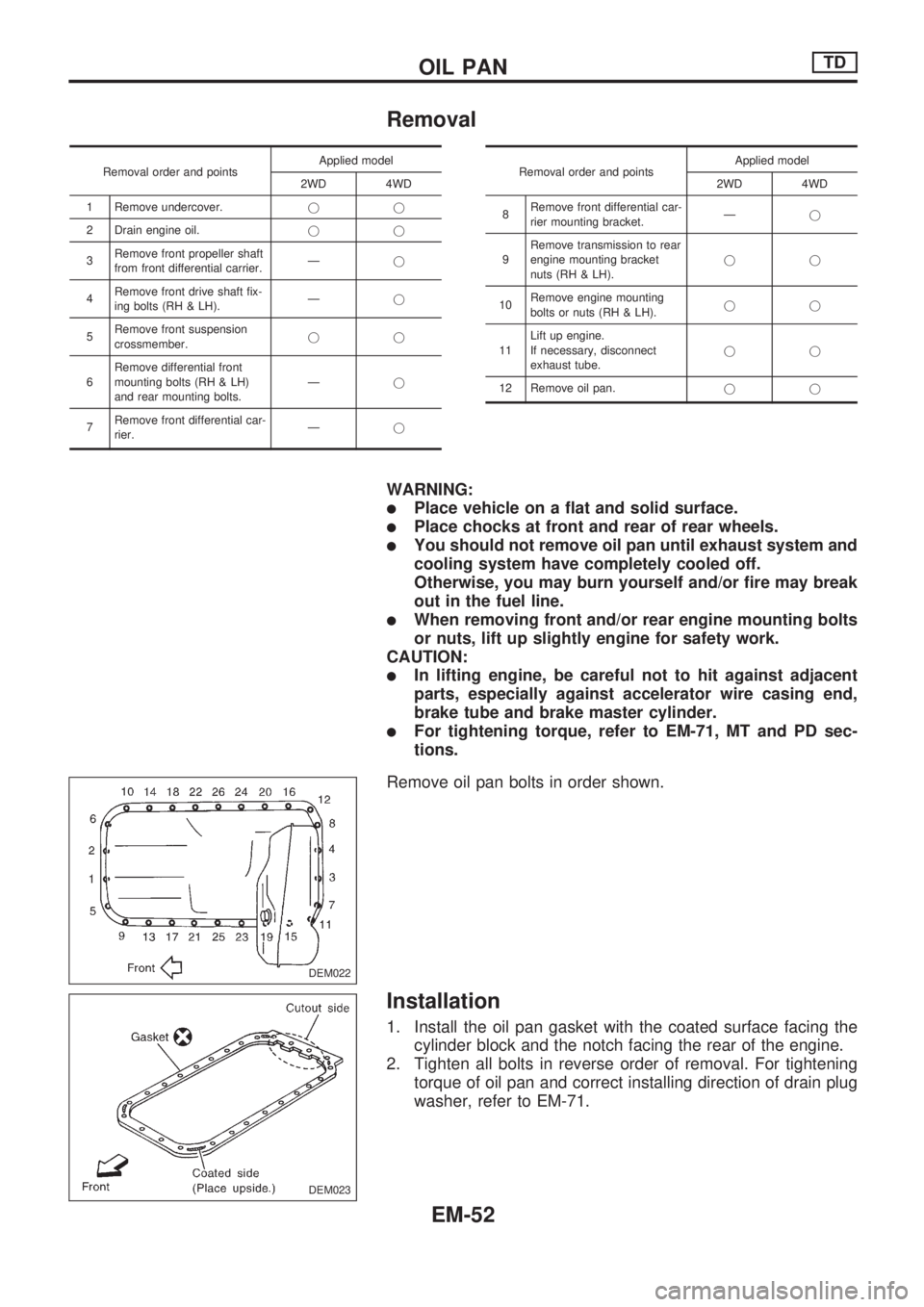
Removal
Removal order and pointsApplied model
2WD 4WD
1 Remove undercover.jj
2 Drain engine oil.jj
3Remove front propeller shaft
from front differential carrier.Ðj
4Remove front drive shaft fix-
ing bolts (RH & LH).Ðj
5Remove front suspension
crossmember.jj
6Remove differential front
mounting bolts (RH & LH)
and rear mounting bolts.Ðj
7Remove front differential car-
rier.ÐjRemoval order and pointsApplied model
2WD 4WD
8Remove front differential car-
rier mounting bracket.Ðj
9Remove transmission to rear
engine mounting bracket
nuts (RH & LH).jj
10Remove engine mounting
bolts or nuts (RH & LH).jj
11Lift up engine.
If necessary, disconnect
exhaust tube.jj
12 Remove oil pan.jj
WARNING:
lPlace vehicle on a flat and solid surface.
lPlace chocks at front and rear of rear wheels.
lYou should not remove oil pan until exhaust system and
cooling system have completely cooled off.
Otherwise, you may burn yourself and/or fire may break
out in the fuel line.
lWhen removing front and/or rear engine mounting bolts
or nuts, lift up slightly engine for safety work.
CAUTION:
lIn lifting engine, be careful not to hit against adjacent
parts, especially against accelerator wire casing end,
brake tube and brake master cylinder.
lFor tightening torque, refer to EM-71, MT and PD sec-
tions.
Remove oil pan bolts in order shown.
Installation
1. Install the oil pan gasket with the coated surface facing the
cylinder block and the notch facing the rear of the engine.
2. Tighten all bolts in reverse order of removal. For tightening
torque of oil pan and correct installing direction of drain plug
washer, refer to EM-71.
DEM022
DEM023
OIL PANTD
EM-52