1998 NISSAN PICK-UP oil temperature
[x] Cancel search: oil temperaturePage 808 of 1659
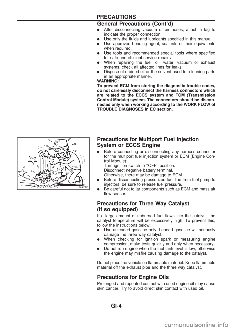
lAfter disconnecting vacuum or air hoses, attach a tag to
indicate the proper connection.
lUse only the fluids and lubricants specified in this manual.
lUse approved bonding agent, sealants or their equivalents
when required.
lUse tools and recommended special tools where specified
for safe and efficient service repairs.
lWhen repairing the fuel, oil, water, vacuum or exhaust
systems, check all affected lines for leaks.
lDispose of drained oil or the solvent used for cleaning parts
in an appropriate manner.
WARNING:
To prevent ECM from storing the diagnostic trouble codes,
do not carelessly disconnect the harness connectors which
are related to the ECCS system and TCM (Transmission
Control Module) system. The connectors should be discon-
nected only when working according to the WORK FLOW of
TROUBLE DIAGNOSES in EC section.
Precautions for Multiport Fuel Injection
System or ECCS Engine
lBefore connecting or disconnecting any harness connector
for the multiport fuel injection system or ECM (Engine Con-
trol Module):
Turn ignition switch to ``OFF'' position.
Disconnect negative battery terminal.
Otherwise, there may be damage to ECM.
lBefore disconnecting pressurized fuel line from fuel pump to
injectors, be sure to release fuel pressure.
lBe careful not to jar components such as ECM and mass air
flow sensor.
Precautions for Three Way Catalyst
(If so equipped)
If a large amount of unburned fuel flows into the catalyst, the
catalyst temperature will be excessively high. To prevent this,
follow the instructions below:
lUse unleaded gasoline only. Leaded gasoline will seriously
damage the three way catalyst.
lWhen checking for ignition spark or measuring engine
compression, make tests quickly and only when necessary.
lDo not run engine when the fuel tank level is low, otherwise
the engine may misfire causing damage to the catalyst.
Do not place the vehicle on flammable material. Keep flammable
material off the exhaust pipe and the three way catalyst.
Precautions for Engine Oils
Prolonged and repeated contact with used engine oil may cause
skin cancer. Try to avoid direct skin contact with used oil.
SGI787
PRECAUTIONS
General Precautions (Cont'd)
GI-4
Page 810 of 1659
DIESEL ENGINE*:
For Europe: diesel fuel of above 50 cetane
* If two types of diesel fuel are available, use summer or win-
ter fuel properly according to the following temperature con-
ditions.
lAbove þ7ÉC (20ÉF) ... Summer type diesel fuel.
lBelow þ7ÉC (20ÉF) ... Winter type diesel fuel.
CAUTION:
lDo not use home heating oil, gasoline, or other alternate
fuels in your diesel engine. The use of those can cause
engine damage.
lDo not use summer fuel at temperature below þ7ÉC
(20ÉF). The cold temperature will cause wax to form in
the fuel. As a result, it may prevent the engine from run-
ning smoothly.
lDo not add gasoline or other alternate fuels to diesel
fuel.
Precautions for Air Conditioning
Use an approved refrigerant recovery unit any time the air con-
ditioning system must be discharged. Refer to HA section
(``HFC-134a (R-134a) Service Procedure'', ``SERVICE PRO-
CEDURES'') for specific instructions.
PRECAUTIONS
Precautions for Fuel (Cont'd)
GI-6
Page 866 of 1659

EVAP vapor lines inspection ....................... MA-22
Electrical diagnoses ...................................... GI-21
Engine compartment .................................... BT-44
Engine control module (ECM) ....................... EC-5
Engine coolant temperature sensor
(ECTS) (KA24 engine) ............................. EC-95
Engine coolant temperature sensor
(ECTS) (TD25 engine) ........................... EC-209
Engine oil filter replacement
(KA24 engine).......................................... MA-20
Engine oil filter replacement
(TD25 engine).......................................... MA-24
Engine oil precautions .................................... GI-4
Engine oil replacement
(KA24 engine).......................................... MA-19
Engine oil replacement
(TD25 engine).......................................... MA-24
Engine outer component parts
(KA24 engine)............................................ EM-9
Engine outer component parts
(TD25 engine).......................................... EM-49
Engine removal (KA24 engine) ................... EM-36
Engine removal (TD25 engine) ................... EM-69
Engine room - See Engine
compartment............................................. BT-44
Engine speed sensor ................................. EC-219
Evaporative emission (EVAP) system ......... EC-19
Exhaust system inspection.......................... MA-32
Exhaust system .............................................. FE-5
Exterior ......................................................... BT-24
F
F/PUMP - Wiring diagram...........................EC-153
FCUT - Wiring diagram ............................. EC-225
FICD - Wiring diagram (KA24 engine) ...... EC-168
FICD - Wiring diagram (TD25 engine) ...... EC-230
Fan switch.................................................... HA-43
Fast idle cam (FIC) inspection and
adjustment................................................ EC-24
Final drive disassembly (C200) ................... PD-34
Final drive disassembly (H233B)................. PD-56
Final drive pre-inspection (C200) ................ PD-34
Final drive pre-inspection (H233B) .............. PD-56
Final drive removal and installation ............. PD-15
Floor trim ...................................................... BT-15
Flow charts.................................................... GI-31
Fluids ........................................................... MA-12
Flywheel (clutch) .......................................... CL-12
Flywheel runout (KA24 engine)................... EM-45
Flywheel runout (TD25 engine)................... EM-80
Fog lamp, rear .............................................. EL-72
Fork rod (M/T) (FS5R30A) .......................... MT-38
Fork rod (M/T) (FS5W71C) ......................... MT-17
Front axle ..................................................... FA-12
Front bumper.................................................. BT-5
Front case (Transfer) ..................................... TF-8
Front combination lamp removal and
installation................................................... BT-5Front disc brake ........................................... BR-21
Front door..................................................... BT-10
Front drive shaft (Transfer) ............................ TF-9
Front final drive disassembly (4WD) ........... PD-17
Front final drive pre-inspection (4WD) ........ PD-17
Front final drive removal and installa-
tion (4WD) ................................................ PD-14
Front seat belt................................................ RS-3
Front seat ..................................................... BT-30
Front suspension.......................................... FA-26
Front washer .............................................. EL-120
Front wiper ................................................. EL-120
Fuel check valve .......................................... EC-20
Fuel cut control (at no load & high
engine speed) (KA24 engine) .................. EC-18
Fuel cut control (at no load & high
engine speed) ........................................ EC-225
Fuel filter replacement (KA24 engine) ........ MA-18
Fuel filter replacement (TD25 engine) ........ MA-27
Fuel injector ............................................... EC-144
Fuel line inspection (KA24 engine) ............. MA-18
Fuel line inspection (TD25 engine) ............. MA-28
Fuel precautions ............................................. GI-5
Fuel pressure check .................................... EC-22
Fuel pressure release .................................. EC-22
Fuel pump .................................................. EC-151
Fuel pump relay ......................................... EC-156
Fuel system .................................................... FE-3
Fuel tank vacuum relief valve...................... EC-20
Fuse block.................................................. Foldout
Fuse.............................................................. EL-13
Fusible link ................................................... EL-13G
GLOW - Wiring diagram .............................EC-197
Garage jack and safety stand....................... GI-49
Gear components (M/T) (FS5R30A) ........... MT-36
Gear components (M/T) (FS5W71C) .......... MT-15
Glass ............................................................ BT-10
Glow plug ................................................... EC-208
Glow relay .................................................. EC-208
Grease ......................................................... MA-12
Ground clearance ......................................... GI-44
Ground distribution ....................................... EL-14
H
H/AIM - Wiring diagram .................................EL-64
H/LAMP - Wiring diagram ............................ EL-44
H02S - Wiring diagram .............................. EC-124
HFC134a (R134a) system precaution ........... HA-2
HFC134a (R134a) system service
procedure ................................................. HA-48
HFC134a (R134a) system service
tools............................................................ HA-8
HFC134a system service equipment
precaution ................................................ HA-10
ALPHABETICAL INDEX
IDX-4
Page 867 of 1659

HLC - Wiring diagram ................................ EL-130
HORN - Wiring diagram ............................. EL-132
H/SEAT - Wiring diagram........................... EL-152
Harness connector ......................................... EL-2
Harness connector inspection ...................... GI-18
Harness layout ........................................... EL-220
Hazard warning lamp ................................... EL-74
Headlamp ..................................................... EL-44
Headlamp aiming control ............................. EL-63
Headlamp leveler - See Headlamp
aiming control ........................................... EL-63
Headlamp washer ...................................... EL-130
Heated oxygen sensor (HO2S) ................. EC-123
Heated oxygen sensor heater ................... EC-127
Heated oxygen sensor inspection ............... MA-22
Heated seat .................................................. BT-32
Heated seat ................................................ EL-152
Height (Dimensions) ..................................... GI-44
Hood ............................................................... BT-5
Horn ............................................................ EL-132
How to erase DTC for ECCS OBD
system ...................................................... EC-36
I
IACV-AAC valve .................................EC-131, 135
IACV-FICD solenoid valve
(KA24 engine) ........................................ EC-168
IACV-FICD solenoid valve
(TD25 engine) ........................................ EC-231
IATS - Wiring diagram ............................... EC-110
IGN/SG - Wiring diagram .......................... EC-101
ILL - Wiring diagram..................................... EL-81
INJECT - Wiring diagram .......................... EC-144
INT/L - Wiring diagram ................................. EL-85
Identification plate ......................................... GI-42
Idle mixture ratio .......................................... EC-25
Idle speed .................................................... EC-25
Idle speed inspection .................................. MA-30
Ignition coil ................................................. EC-105
Ignition timing............................................... EC-25
Ignition wire inspection ................................ MA-21
Illumination ................................................... EL-81
Injection nozzle inspection .......................... MA-29
Injection nozzle .......................................... EC-186
Injector ............................................... EC-144, 148
Injector removal and installation .................. EC-23
Instrument panel .......................................... BT-12
Intake air temperature sensor ................... EC-109
Intake door control linkage
adjustment................................................ HA-47
Intake manifold .............................................. EM-9
Interior lamp ................................................. EL-85
Interior .......................................................... BT-15
J
Jacking points ................................................GI-47Journal bearing assembly
(propeller shaft) ........................................ PD-11
Journal bearing disassembly
(propeller shaft) ........................................ PD-10
Jump seat..................................................... BT-34
K
Keyless entry system - See Multi-remote
control system .............................................EL-173
Knuckle spindle ............................................ FA-18
L
LSV (Load sensing valve)...............................BR-7
Leaf spring (rear) ......................................... RA-13
Length (Dimensions) ..................................... GI-44
License lamp ................................................ EL-66
Lifting points .................................................. GI-47
Limited slip diff. adjustment (C200) ............. PD-41
Limited slip diff. adjustment (H233B) .......... PD-63
Limited slip diff. assembly (C200) ............... PD-43
Limited slip diff. assembly (H233B) ............. PD-64
Limited slip diff. disassembly (C200)........... PD-39
Limited slip diff. disassembly (H233B) ........ PD-61
Limited slip diff. inspection (C200) .............. PD-40
Limited slip diff. inspection (H233B) ............ PD-62
Liquid gasket application ............................... EM-1
Location of electrical units.......................... EL-217
Lock, door .................................................... BT-10
Lubricant (R134a) A/C ................................. HA-50
Lubricants .................................................... MA-12
Lubrication circuit (engine)
(KA24 engine) ............................................ LC-3
Lubrication circuit (engine)
(TD25 engine) .......................................... LC-12
Lubrication-locks, hinges and hood
latches ..................................................... MA-39
M
M/T major overhaul (FS5R30A) ...................MT-35
M/T major overhaul (FS5W71C) ................. MT-14
M/T removal and installation ....................... MT-11
MAFS - Wiring diagram ............................... EC-91
MAIN - Wiring diagram ................................ EC-76
METER - Wiring diagram ............................. EL-90
MIL & Data link connectors ....................... EC-173
MIRROR - Wiring diagram ......................... EL-150
MULTI - Wiring diagram ............................. EL-175
Main drive gear (M/T) (FS5R30A)............... MT-36
Main drive gear (M/T) (FS5W71C).............. MT-15
Main gear (Transfer) ...................................... TF-9
Mainshaft (M/T) (FS5R30A) ........................ MT-36
Mainshaft (M/T) (FS5W71C) ....................... MT-15
Mainshaft (Transfer) ....................................... TF-9
Maintenance (engine) (KA24 engine) ......... MA-15
ALPHABETICAL INDEX
IDX-5
Page 869 of 1659
Radiator (KA24 engine) ................................. LC-9
Radiator (TD25 engine) ............................... LC-24
Rear axle ....................................................... RA-5
Rear body..................................................... BT-40
Rear case (Transfer) ...................................... TF-8
Rear combination lamp removal and
installation................................................. BT-24
Rear cover gasket replacement diff. ........... PD-13
Rear door ..................................................... BT-11
Rear drum brake.......................................... BR-26
Rear fog lamp............................................... EL-72
Rear seat belt ................................................ RS-4
Rear seat...................................................... BT-33
Rear suspension .......................................... RA-12
Rear window defogger ............................... EL-135
Refrigerant connection precaution................. HA-2
Refrigerant discharging evacuating
charging ................................................... HA-49
Refrigerant general precaution ...................... HA-2
Refrigerant lines........................................... HA-52
Refrigeration cycle ....................................... HA-12
Release bearing (clutch) ................................ CL-9
Removal and installation (Transfer) ............... TF-6
Resistor ...................................................... EC-105
Reverse idler shaft (M/T) (FS5R30A) ......... MT-36
Reverse idler shaft (M/T) (FS5W71C) ........ MT-15
Reverse lamp switch (M/T) - See
Back-up lamp switch (M/T) ........................ MT-9
Reverse main gear (M/T) (FS5R30A) ......... MT-36
Reverse main gear (M/T) (FS5W71C) ........ MT-15
Ring gear diff. inspection (C200)................. PD-38
Ring gear diff. inspection (H233B) .............. PD-60
Road wheel size ........................................... GI-46
Roof trim....................................................... BT-21
Room lamp - See Interior lamp.................... EL-85
Rotor disc (front) .......................................... FA-16
S
S/SIG - Wiring diagram...............................EC-149
SAE J1930 terminology list........................... GI-55
SMJ (super multiple junction) .................... Foldout
SRS - See Supplemental Restraint
System ....................................................... RS-6
SRS Trouble diagnoses
(2WD models) .......................................... RS-17
SRS Trouble diagnoses
(4WD models) .......................................... RS-22
START - Wiring diagram .............................. EL-26
SWL/V - Wiring diagram ............................ EC-163
Screw jack..................................................... GI-48
Seal - See Exterior....................................... BT-24
Seat belt inspection ..................................... MA-40
Seat belt, front ............................................... RS-3
Seat belt, rear ................................................ RS-4
Seat, front..................................................... BT-30
Seat, rear ..................................................... BT-33
Self-diagnostic results.................................. EC-38
Shift control (Transfer) ................................. TF-10Shift control components (M/T)
(FS5R30A) ................................................MT-38
Shift control components (M/T)
(FS5W71C) .............................................. MT-17
Shift fork (M/T) (FS5R30A) ......................... MT-38
Shift fork (M/T) (FS5W71C) ........................ MT-17
Shift lever (FS5R30A) ................................. MT-38
Shift lever (FS5W71C) ................................ MT-17
Shock absorber (front) ................................. FA-28
Shock absorber (rear).................................. RA-13
Side bearing preload (R180A) ..................... PD-23
Side bearing preload (C200) ....................... PD-45
Side trim ....................................................... BT-15
Side window ................................................. BT-38
Spark plug replacement .............................. MA-20
Spiral cable .................................................. RS-11
Spot lamp ..................................................... EL-85
Stabilizer bar (front) ..................................... FA-31
Standardized relay ......................................... EL-3
Start signal ................................................. EC-149
Starter ........................................................... EL-33
Starting system............................................. EL-26
Steering gear and linkage inspection.......... MA-37
Steering gear oil level ................................. MA-38
Steering knuckle........................................... FA-18
Steering linkage ........................................... ST-37
Steering wheel and column ........................... ST-9
Steering wheel play........................................ ST-6
Steering wheel turning force .......................... ST-6
Striking rod (M/T) (FS5R30A) ..................... MT-38
Striking rod (M/T) (FS5W71C) .................... MT-17
Sub-gear (M/T) (FS5R30A) ......................... MT-36
Sub-gear (M/T) (FS5W71C) ........................ MT-15
Sunroof ......................................................... BT-35
Supplemental Restraint System .................... RS-6
Supplemental restraint system - Wiring
diagram (2WD models) ............................ RS-18
Supplemental restraint system - Wiring
diagram (4WD models) ............................ RS-26
Swirl control valve control solenoid
valve ....................................................... EC-161
Symbols and abbreviations............................. GI-8
Synchronizer (M/T) (FS5R30A) ................... MT-36
Synchronizer (M/T) (FS5W71C) .................. MT-15
T
TAIL/L - Wiring diagram ................................EL-66
TPS - Wiring diagram ................................ EC-115
TURN - Wiring diagram................................ EL-75
Tail lamp ....................................................... EL-66
Temperature control cable and linkage
adjustment................................................ HA-47
Tension rod (front) ....................................... FA-33
Thermal protector ........................................ HA-45
Thermo control amp .................................... HA-44
Thermostat (KA24 engine) ............................. LC-8
Thermostat (TD25 engine) ........................... LC-23
Three way catalyst precautions ...................... GI-4
ALPHABETICAL INDEX
IDX-7
Page 876 of 1659
WARNING:
Make sure all refrigerant is discharged into the recycling equipment and the pressure in the system
is less than atmospheric pressure. Then gradually loosen the discharge side hose fitting and remove
it.
CAUTION:
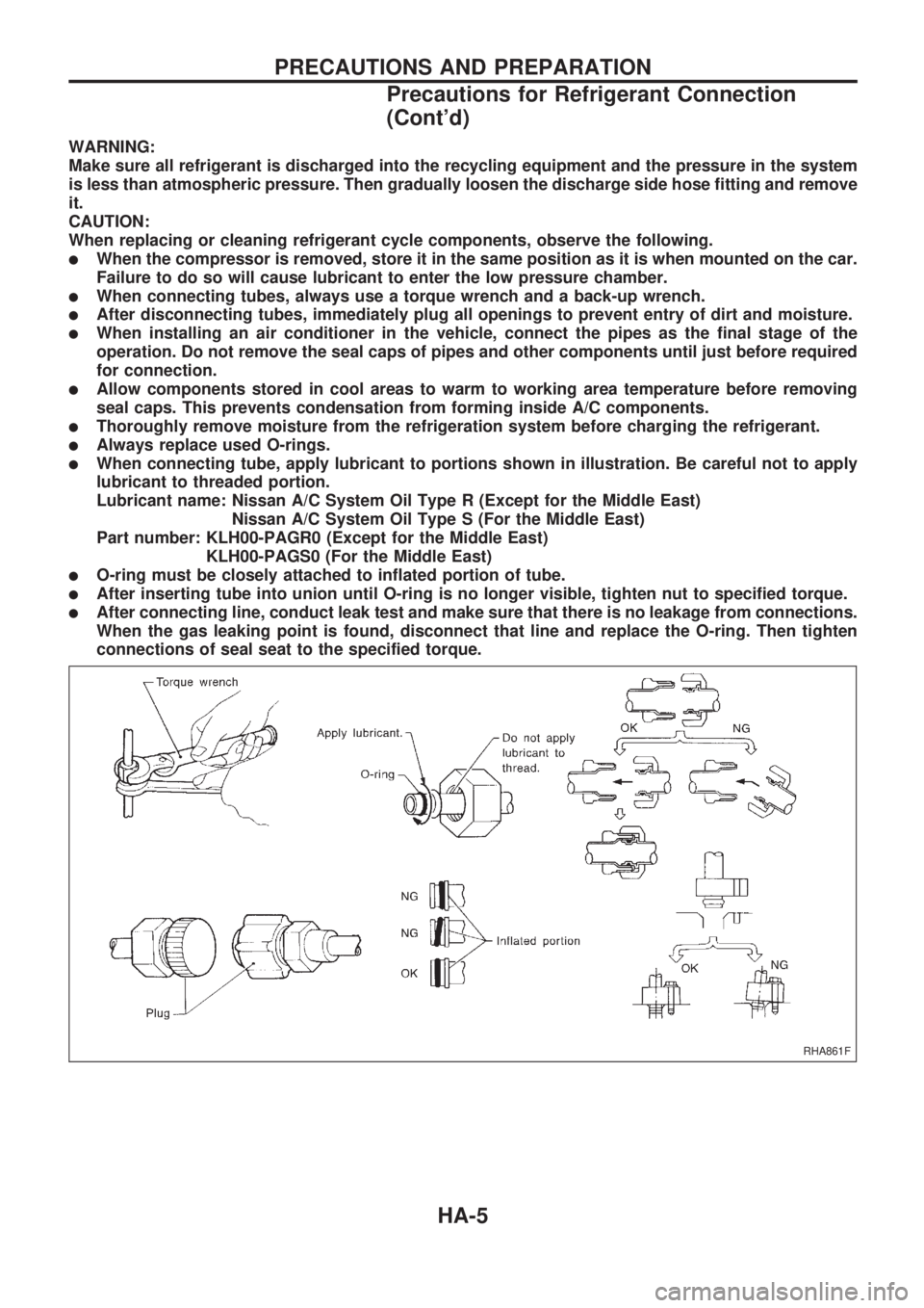
When replacing or cleaning refrigerant cycle components, observe the following.
lWhen the compressor is removed, store it in the same position as it is when mounted on the car.
Failure to do so will cause lubricant to enter the low pressure chamber.
lWhen connecting tubes, always use a torque wrench and a back-up wrench.
lAfter disconnecting tubes, immediately plug all openings to prevent entry of dirt and moisture.
lWhen installing an air conditioner in the vehicle, connect the pipes as the final stage of the
operation. Do not remove the seal caps of pipes and other components until just before required
for connection.
lAllow components stored in cool areas to warm to working area temperature before removing
seal caps. This prevents condensation from forming inside A/C components.
lThoroughly remove moisture from the refrigeration system before charging the refrigerant.
lAlways replace used O-rings.
lWhen connecting tube, apply lubricant to portions shown in illustration. Be careful not to apply
lubricant to threaded portion.
Lubricant name: Nissan A/C System Oil Type R (Except for the Middle East)
Nissan A/C System Oil Type S (For the Middle East)
Part number: KLH00-PAGR0 (Except for the Middle East)
KLH00-PAGS0 (For the Middle East)
lO-ring must be closely attached to inflated portion of tube.
lAfter inserting tube into union until O-ring is no longer visible, tighten nut to specified torque.
lAfter connecting line, conduct leak test and make sure that there is no leakage from connections.
When the gas leaking point is found, disconnect that line and replace the O-ring. Then tighten
connections of seal seat to the specified torque.
RHA861F
PRECAUTIONS AND PREPARATION
Precautions for Refrigerant Connection
(Cont'd)
HA-5
Page 883 of 1659
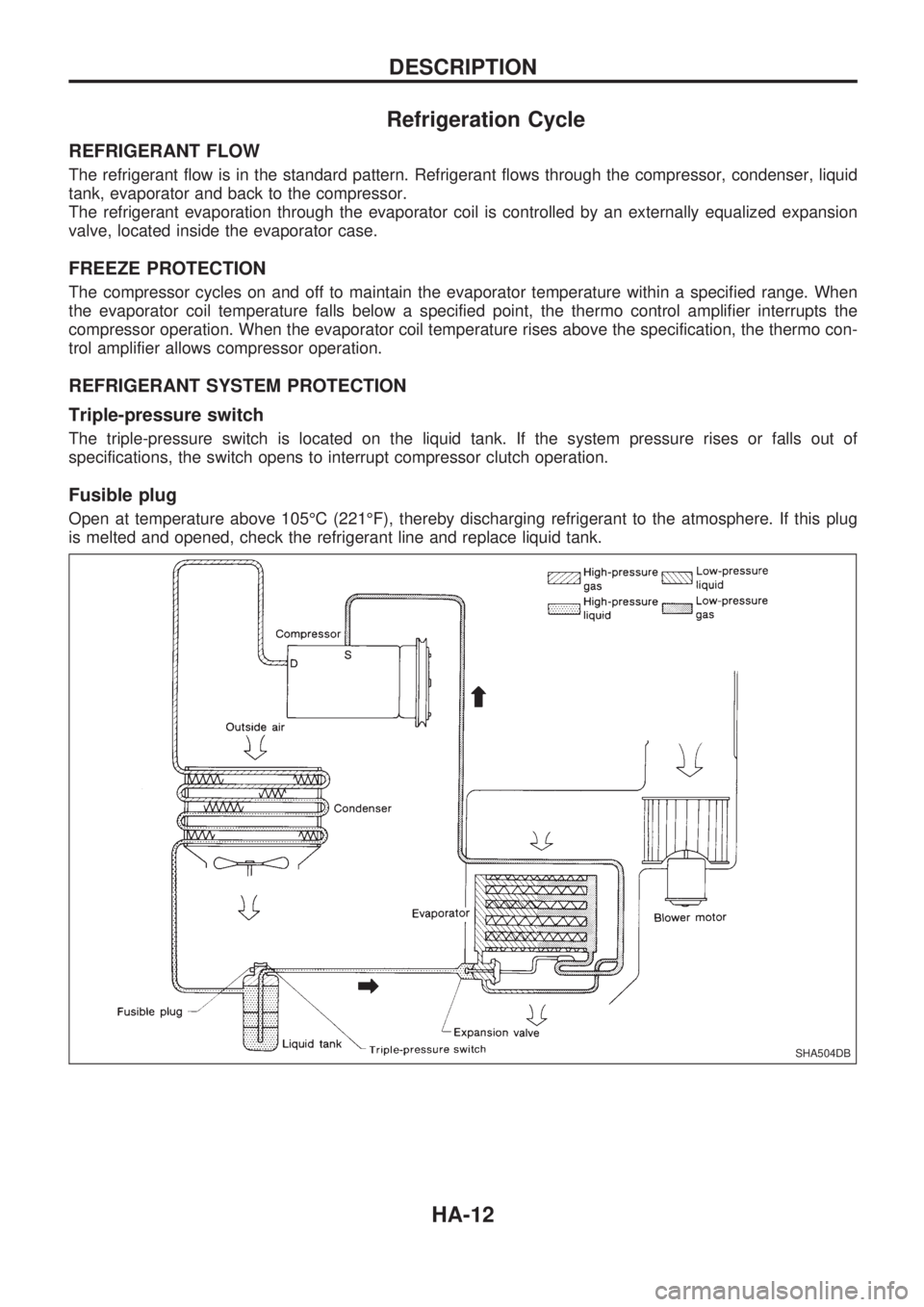
Refrigeration Cycle
REFRIGERANT FLOW
The refrigerant flow is in the standard pattern. Refrigerant flows through the compressor, condenser, liquid
tank, evaporator and back to the compressor.
The refrigerant evaporation through the evaporator coil is controlled by an externally equalized expansion
valve, located inside the evaporator case.
FREEZE PROTECTION
The compressor cycles on and off to maintain the evaporator temperature within a specified range. When
the evaporator coil temperature falls below a specified point, the thermo control amplifier interrupts the
compressor operation. When the evaporator coil temperature rises above the specification, the thermo con-
trol amplifier allows compressor operation.
REFRIGERANT SYSTEM PROTECTION
Triple-pressure switch
The triple-pressure switch is located on the liquid tank. If the system pressure rises or falls out of
specifications, the switch opens to interrupt compressor clutch operation.
Fusible plug
Open at temperature above 105ÉC (221ÉF), thereby discharging refrigerant to the atmosphere. If this plug
is melted and opened, check the refrigerant line and replace liquid tank.
SHA504DB
DESCRIPTION
HA-12
Page 892 of 1659
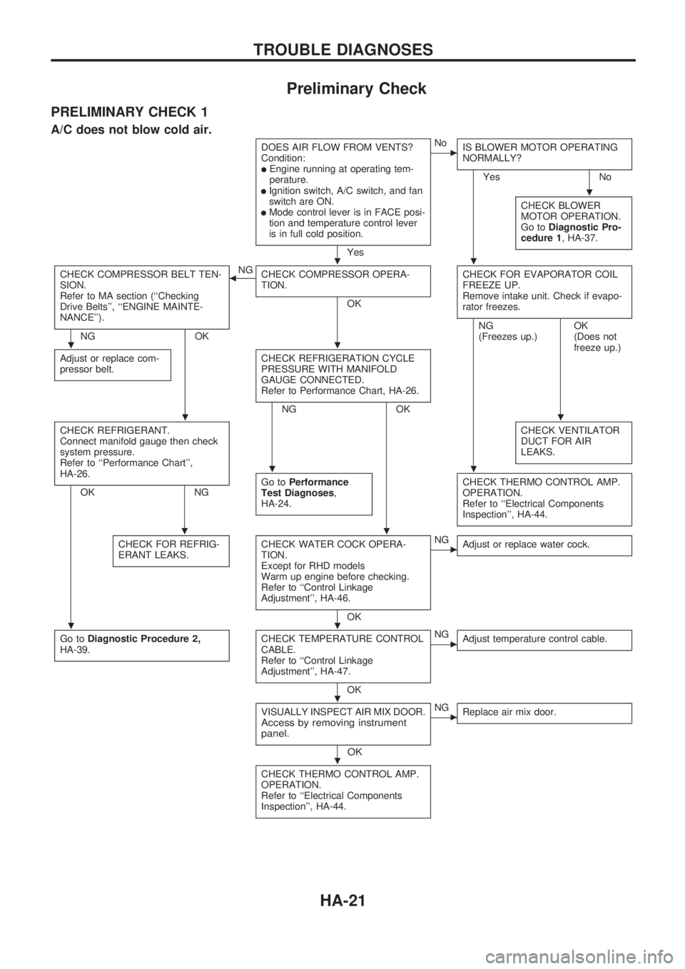
Preliminary Check
PRELIMINARY CHECK 1
A/C does not blow cold air.
DOES AIR FLOW FROM VENTS?
Condition:
lEngine running at operating tem-
perature.
lIgnition switch, A/C switch, and fan
switch are ON.
lMode control lever is in FACE posi-
tion and temperature control lever
is in full cold position.
Yes
cNo
IS BLOWER MOTOR OPERATING
NORMALLY?
Yes No
CHECK BLOWER
MOTOR OPERATION.
Go toDiagnostic Pro-
cedure 1, HA-37.
CHECK COMPRESSOR BELT TEN-
SION.
Refer to MA section (``Checking
Drive Belts'', ``ENGINE MAINTE-
NANCE'').
NG OKNG
bCHECK COMPRESSOR OPERA-
TION.
OKCHECK FOR EVAPORATOR COIL
FREEZE UP.
Remove intake unit. Check if evapo-
rator freezes.
Adjust or replace com-
pressor belt.CHECK REFRIGERATION CYCLE
PRESSURE WITH MANIFOLD
GAUGE CONNECTED.
Refer to Performance Chart, HA-26.
NG OKNG
(Freezes up.)OK
(Does not
freeze up.)
CHECK REFRIGERANT.
Connect manifold gauge then check
system pressure.
Refer to ``Performance Chart'',
HA-26.
OK NGCHECK VENTILATOR
DUCT FOR AIR
LEAKS.Go toPerformance
Test Diagnoses,
HA-24.CHECK THERMO CONTROL AMP.
OPERATION.
Refer to ``Electrical Components
Inspection'', HA-44.
CHECK FOR REFRIG-
ERANT LEAKS.CHECK WATER COCK OPERA-
TION.
Except for RHD models
Warm up engine before checking.
Refer to ``Control Linkage
Adjustment'', HA-46.
OK
cNG
Adjust or replace water cock.
Go toDiagnostic Procedure 2,
HA-39.CHECK TEMPERATURE CONTROL
CABLE.
Refer to ``Control Linkage
Adjustment'', HA-47.
OK
cNG
Adjust temperature control cable.
VISUALLY INSPECT AIR MIX DOOR.Access by removing instrument
panel.
OK
cNG
Replace air mix door.
CHECK THERMO CONTROL AMP.
OPERATION.
Refer to ``Electrical Components
Inspection'', HA-44.
.
..
..
..
..
..
..
.
.
TROUBLE DIAGNOSES
HA-21