1998 NISSAN PICK-UP oil temperature
[x] Cancel search: oil temperaturePage 259 of 1659
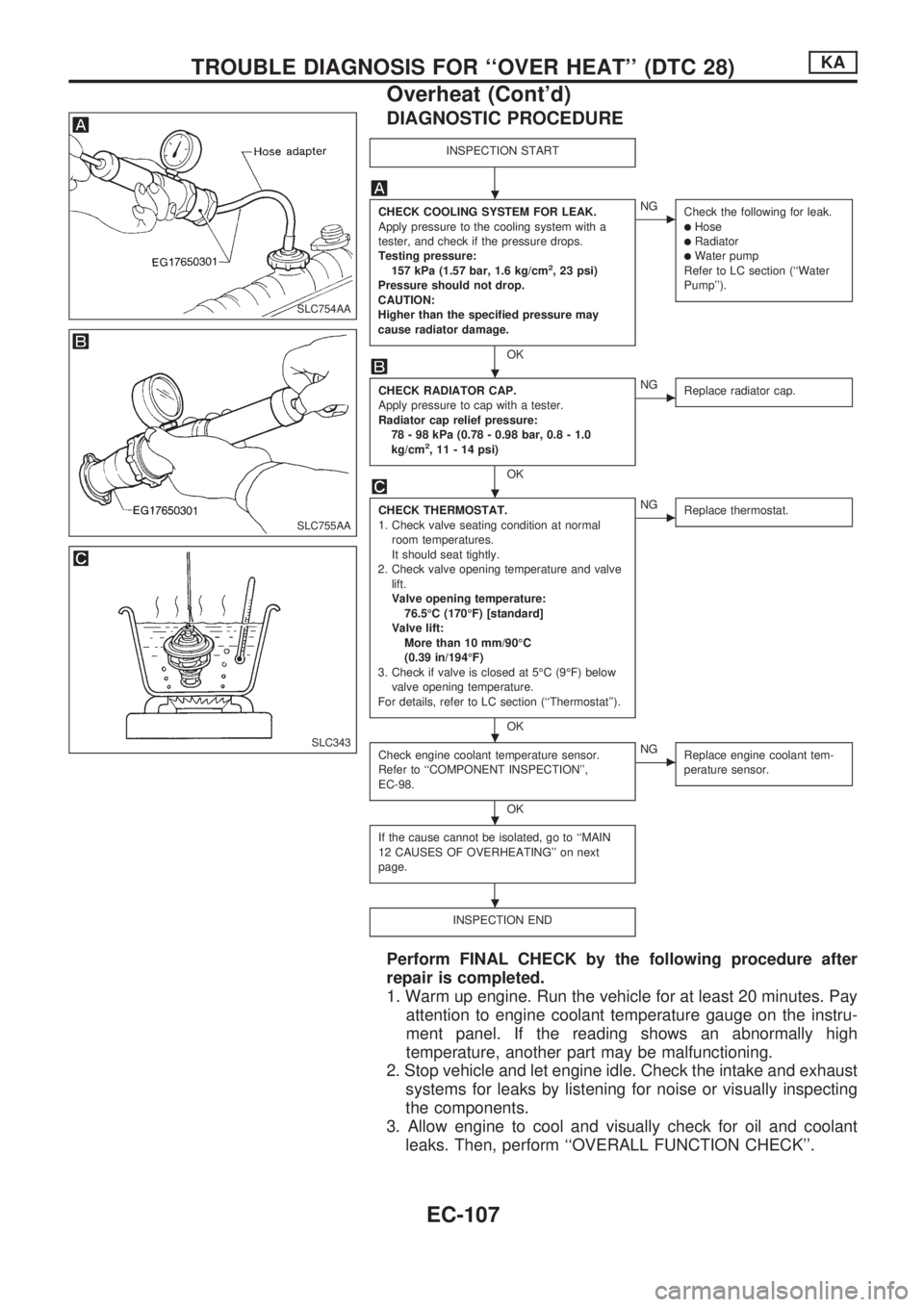
DIAGNOSTIC PROCEDURE
INSPECTION START
CHECK COOLING SYSTEM FOR LEAK.
Apply pressure to the cooling system with a
tester, and check if the pressure drops.
Testing pressure:
157 kPa (1.57 bar, 1.6 kg/cm
2, 23 psi)
Pressure should not drop.
CAUTION:
Higher than the specified pressure may
cause radiator damage.
OK
cNG
Check the following for leak.
lHoselRadiatorlWater pump
Refer to LC section (``Water
Pump'').
CHECK RADIATOR CAP.
Apply pressure to cap with a tester.
Radiator cap relief pressure:
78 - 98 kPa (0.78 - 0.98 bar, 0.8 - 1.0
kg/cm
2, 11 - 14 psi)
OK
cNG
Replace radiator cap.
CHECK THERMOSTAT.
1. Check valve seating condition at normal
room temperatures.
It should seat tightly.
2. Check valve opening temperature and valve
lift.
Valve opening temperature:
76.5ÉC (170ÉF) [standard]
Valve lift:
More than 10 mm/90ÉC
(0.39 in/194ÉF)
3. Check if valve is closed at 5ÉC (9ÉF) below
valve opening temperature.
For details, refer to LC section (``Thermostat'').
OK
cNG
Replace thermostat.
Check engine coolant temperature sensor.
Refer to ``COMPONENT INSPECTION'',
EC-98.
OK
cNG
Replace engine coolant tem-
perature sensor.
If the cause cannot be isolated, go to ``MAIN
12 CAUSES OF OVERHEATING'' on next
page.
INSPECTION END
Perform FINAL CHECK by the following procedure after
repair is completed.
1. Warm up engine. Run the vehicle for at least 20 minutes. Pay
attention to engine coolant temperature gauge on the instru-
ment panel. If the reading shows an abnormally high
temperature, another part may be malfunctioning.
2. Stop vehicle and let engine idle. Check the intake and exhaust
systems for leaks by listening for noise or visually inspecting
the components.
3. Allow engine to cool and visually check for oil and coolant
leaks. Then, perform ``OVERALL FUNCTION CHECK''.
SLC754AA
SLC755AA
SLC343
.
.
.
.
.
.
TROUBLE DIAGNOSIS FOR ``OVER HEAT'' (DTC 28)KA
Overheat (Cont'd)
EC-107
Page 283 of 1659
Idle Air Control Valve (IACV) Ð Auxiliary Air
Control (AAC) Valve
SYSTEM DESCRIPTION
Camshaft position sensorcEngine speed
ECM
(ECCS
control
module)
cIACV-AAC valve
Mass air flow sensorcAmount of intake air
Engine coolant temperature sensor
cEngine coolant temperature
Ignition switch
cStart signal
Throttle position sensor
cThrottle position
Neutral position switch
cNeutral position
Air conditioner switch
cAir conditioner operation
Power steering oil pressure switch
cPower steering load signal
Battery
cBattery voltage
Vehicle speed sensor
cVehicle speed
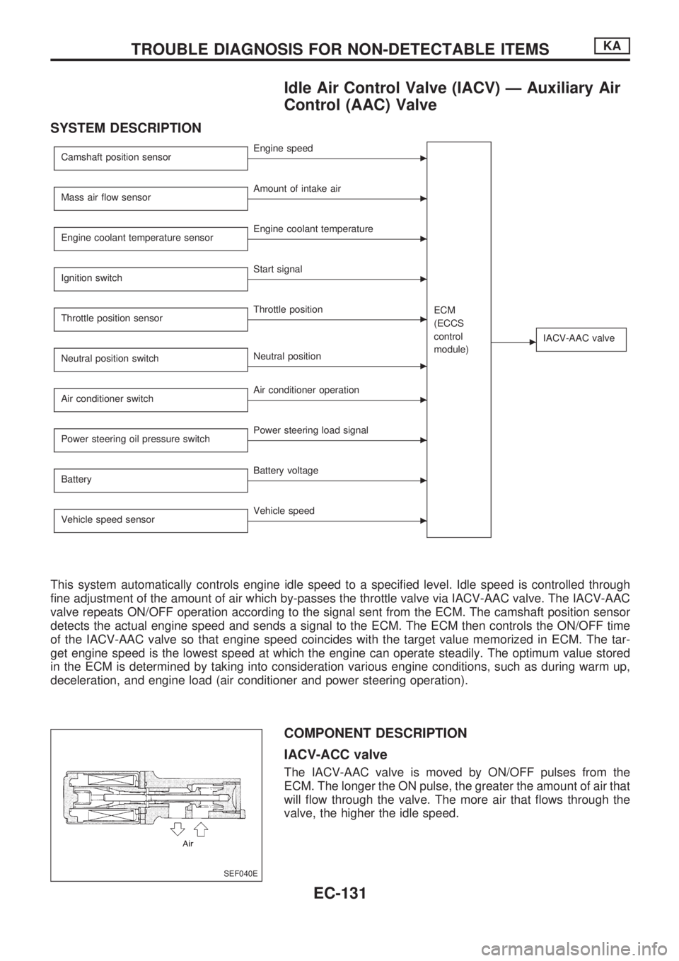
This system automatically controls engine idle speed to a specified level. Idle speed is controlled through
fine adjustment of the amount of air which by-passes the throttle valve via IACV-AAC valve. The IACV-AAC
valve repeats ON/OFF operation according to the signal sent from the ECM. The camshaft position sensor
detects the actual engine speed and sends a signal to the ECM. The ECM then controls the ON/OFF time
of the IACV-AAC valve so that engine speed coincides with the target value memorized in ECM. The tar-
get engine speed is the lowest speed at which the engine can operate steadily. The optimum value stored
in the ECM is determined by taking into consideration various engine conditions, such as during warm up,
deceleration, and engine load (air conditioner and power steering operation).
COMPONENT DESCRIPTION
IACV-ACC valve
The IACV-AAC valve is moved by ON/OFF pulses from the
ECM. The longer the ON pulse, the greater the amount of air that
will flow through the valve. The more air that flows through the
valve, the higher the idle speed.
SEF040E
TROUBLE DIAGNOSIS FOR NON-DETECTABLE ITEMSKA
EC-131
Page 378 of 1659
Description
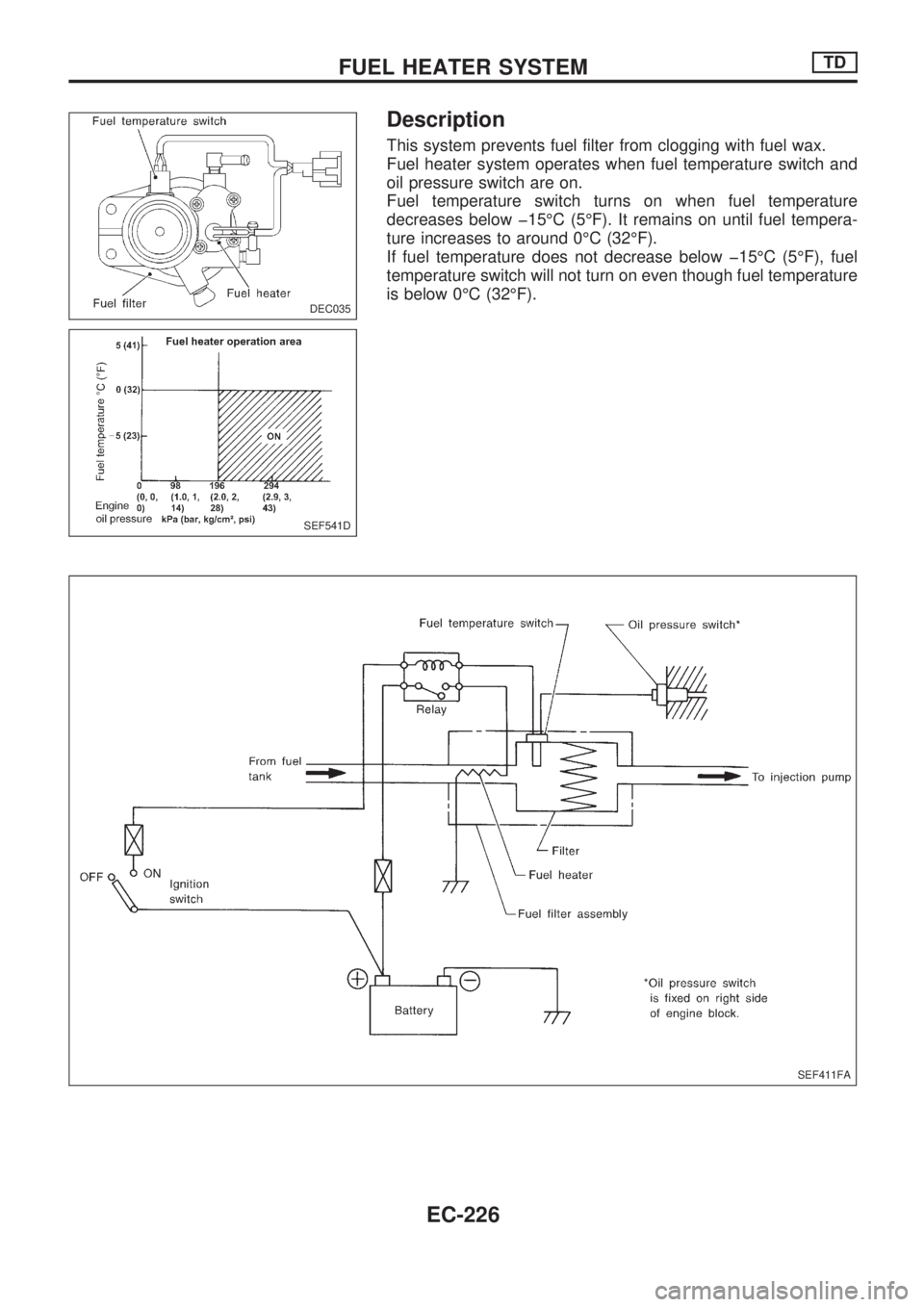
This system prevents fuel filter from clogging with fuel wax.
Fuel heater system operates when fuel temperature switch and
oil pressure switch are on.
Fuel temperature switch turns on when fuel temperature
decreases below þ15ÉC (5ÉF). It remains on until fuel tempera-
ture increases to around 0ÉC (32ÉF).
If fuel temperature does not decrease below þ15ÉC (5ÉF), fuel
temperature switch will not turn on even though fuel temperature
is below 0ÉC (32ÉF).
DEC035
SEF541D
SEF411FA
FUEL HEATER SYSTEMTD
EC-226
Page 381 of 1659
When installing, use a new O-ring.
WARNING:
Do not touch the cooled fuel temperature switch with your
bare hand.
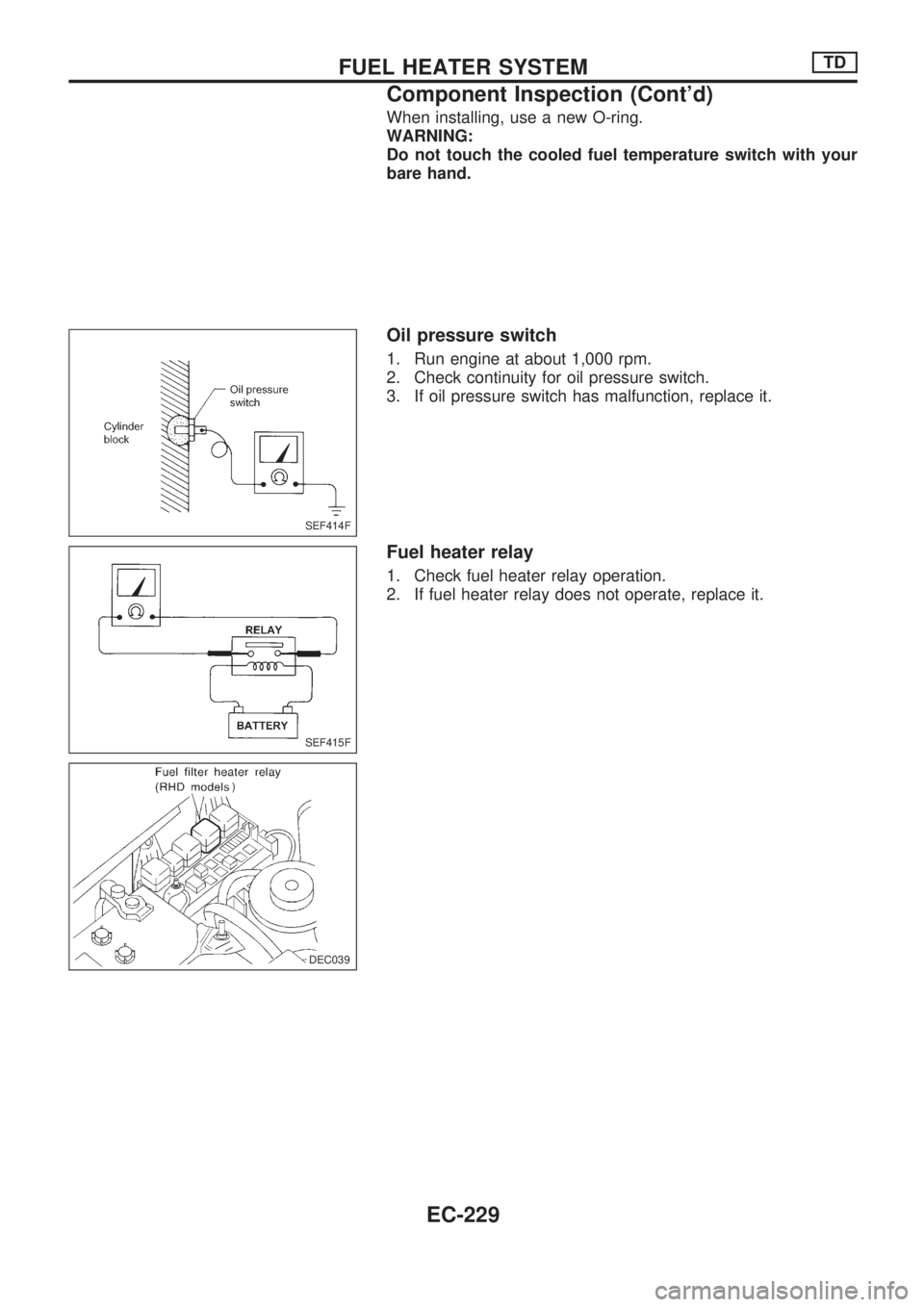
Oil pressure switch
1. Run engine at about 1,000 rpm.
2. Check continuity for oil pressure switch.
3. If oil pressure switch has malfunction, replace it.
Fuel heater relay
1. Check fuel heater relay operation.
2. If fuel heater relay does not operate, replace it.
SEF414F
SEF415F
DEC039
.)
.DEC039
FUEL HEATER SYSTEMTD
Component Inspection (Cont'd)
EC-229
Page 384 of 1659
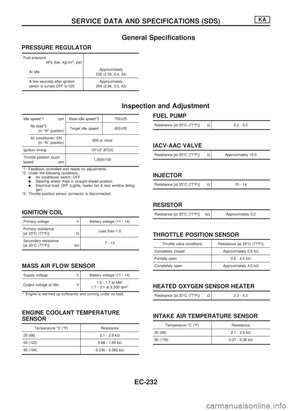
General Specifications
PRESSURE REGULATOR
Fuel pressure
kPa (bar, kg/cm2, psi)
At idleApproximately
235 (2.35, 2.4, 34)
A few seconds after ignition
switch is turned OFF to ONApproximately
294 (2.94, 3.0, 43)
Inspection and Adjustment
Idle speed*1 rpm Base idle speed*3 750 25
No-load*2
(in ``N'' position)Target idle speed 800 50
Air conditioner: ON
(in ``N'' position)900 or more
Ignition timing 10É 2É BTDC
Throttle position touch
speed rpm1,000 150
*1: Feedback controlled and needs no adjustments
*2: Under the following conditions:
lAir conditioner switch: OFFlSteering wheel: Kept in straight-ahead positionlElectrical load: OFF (Lights, heater fan & rear window defog-
ger)
*3: Throttle position sensor connector is disconnected.
IGNITION COIL
Primary voltage V Battery voltage (11 - 14)
Primary resistance
[at 25ÉC (77ÉF)]WLess than 1.0
Secondary resistance
[at 25ÉC (77ÉF)] kW7-13
MASS AIR FLOW SENSOR
Supply voltage V Battery voltage (11 - 14)
Output voltage at idle V1.3 - 1.7 at idle*
1.7 - 2.1 at 2,500 rpm*
*: Engine is warmed up sufficiently and running under no-load.
ENGINE COOLANT TEMPERATURE
SENSOR
Temperature ÉC (ÉF) Resistance
20 (68) 2.1 - 2.9 kW
50 (122) 0.68 - 1.00 kW
90 (194) 0.236 - 0.260 kW
FUEL PUMP
Resistance [at 25ÉC (77ÉF)]W0.2 - 5.0
IACV-AAC VALVE
Resistance [at 25ÉC (77ÉF)]WApproximately 10.0
INJECTOR
Resistance [at 25ÉC (77ÉF)]W10-14
RESISTOR
Resistance [at 25ÉC (77ÉF)] kWApproximately 2.2
THROTTLE POSITION SENSOR
Throttle valve conditions Resistance [at 25ÉC (77ÉF)]
Completely closed Approximately 0.6 kW
Partially open 0.6 - 4.0 kW
Completely open Approximately 4.0 kW
HEATED OXYGEN SENSOR HEATER
Resistance [at 25ÉC (77ÉF)]W2.3 - 4.3
INTAKE AIR TEMPERATURE SENSOR
Temperature ÉC (ÉF) Resistance
20 (68) 2.1 - 2.9 kW
80 (176) 0.27 - 0.38 kW
SERVICE DATA AND SPECIFICATIONS (SDS)KA
EC-232
Page 386 of 1659
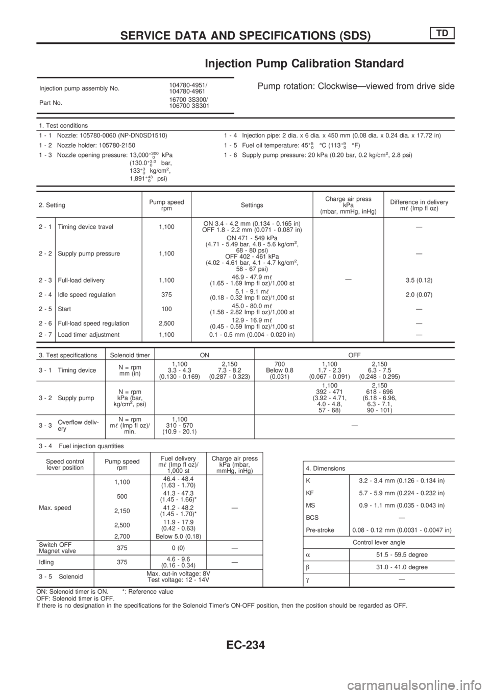
Injection Pump Calibration Standard
Injection pump assembly No.104780-4951/
104780-4961
Part No.16700 3S300/
106700 3S301Pump rotation: ClockwiseÐviewed from drive side
1. Test conditions
1 - 1 Nozzle: 105780-0060 (NP-DN0SD1510) 1 - 4 Injection pipe: 2 dia. x 6 dia. x 450 mm (0.08 dia. x 0.24 dia. x 17.72 in)
1 - 2 Nozzle holder: 105780-2150 1 - 5 Fuel oil temperature: 45
+5
0ÉC (113+9
0ÉF)
1 - 3 Nozzle opening pressure: 13,000+300
0kPa
(130.0+3.0
0bar,
133+3
0kg/cm2,
1,891+43
0psi)1 - 6 Supply pump pressure: 20 kPa (0.20 bar, 0.2 kg/cm
2, 2.8 psi)
2. SettingPump speed
rpmSettingsCharge air press
kPa
(mbar, mmHg, inHg)Difference in delivery
m!(Imp fl oz)
2 - 1 Timing device travel 1,100ON 3.4 - 4.2 mm (0.134 - 0.165 in)
OFF 1.8 - 2.2 mm (0.071 - 0.087 in)
ÐÐ
2 - 2 Supply pump pressure 1,100ON 471 - 549 kPa
(4.71 - 5.49 bar, 4.8 - 5.6 kg/cm
2,
68 - 80 psi)
OFF 402 - 461 kPa
(4.02 - 4.61 bar, 4.1 - 4.7 kg/cm
2,
58 - 67 psi)Ð
2 - 3 Full-load delivery 1,10046.9 - 47.9 m!
(1.65 - 1.69 Imp fl oz)/1,000 st3.5 (0.12)
2 - 4 Idle speed regulation 3755.1 - 9.1 m!
(0.18 - 0.32 Imp fl oz)/1,000 st2.0 (0.07)
2 - 5 Start 10045.0 - 80.0 m!
(1.58 - 2.82 Imp fl oz)/1,000 stÐ
2 - 6 Full-load speed regulation 2,50012.9 - 16.9 m!
(0.45 - 0.59 Imp fl oz)/1,000 stÐ
2 - 7 Load timer adjustment 1,100 0.1 - 0.5 mm (0.004 - 0.020 in) Ð
3. Test specifications Solenoid timer ON OFF
3 - 1 Timing deviceN = rpm
mm (in)1,100
3.3 - 4.3
(0.130 - 0.169)2,150
7.3 - 8.2
(0.287 - 0.323)700
Below 0.8
(0.031)1,100
1.7 - 2.3
(0.067 - 0.091)2,150
6.3 - 7.5
(0.248 - 0.295)
3 - 2 Supply pumpN = rpm
kPa (bar,
kg/cm
2, psi)1,100
392 - 471
(3.92 - 4.71,
4.0 - 4.8,
57 - 68)2,150
618 - 696
(6.18 - 6.96,
6.3 - 7.1,
90 - 101)
3-3Overflow deliv-
eryN = rpm
m!(Imp fl oz)/
min.1,100
310 - 570
(10.9 - 20.1)Ð
3 - 4 Fuel injection quantities
Speed control
lever positionPump speed
rpmFuel delivery
m!(Imp fl oz)/
1,000 stCharge air press
kPa (mbar,
mmHg, inHg)
Max. speed1,10046.4 - 48.4
(1.63 - 1.70)
Ð 50041.3 - 47.3
(1.45 - 1.66)*
2,15041.2 - 48.2
(1.45 - 1.70)*
2,50011.9 - 17.9
(0.42 - 0.63)
2,700 Below 5.0 (0.18)
Switch OFF
Magnet valve375 0 (0) Ð
Idling 3754.6 - 9.6
(0.16 - 0.34)Ð
3 - 5 SolenoidMax. cut-in voltage: 8V
Test voltage: 12 - 14V
ON: Solenoid timer is ON. *: Reference value
OFF: Solenoid timer is OFF.
If there is no designation in the specifications for the Solenoid Timer's ON-OFF position, then the position should be regarded as OFF.
4. Dimensions
K 3.2 - 3.4 mm (0.126 - 0.134 in)
KF 5.7 - 5.9 mm (0.224 - 0.232 in)
MS 0.9 - 1.1 mm (0.035 - 0.043 in)
BCS Ð
Pre-stroke 0.08 - 0.12 mm (0.0031 - 0.0047 in)
Control lever angle
a51.5 - 59.5 degree
b31.0 - 41.0 degree
gÐ
SERVICE DATA AND SPECIFICATIONS (SDS)TD
EC-234
Page 407 of 1659
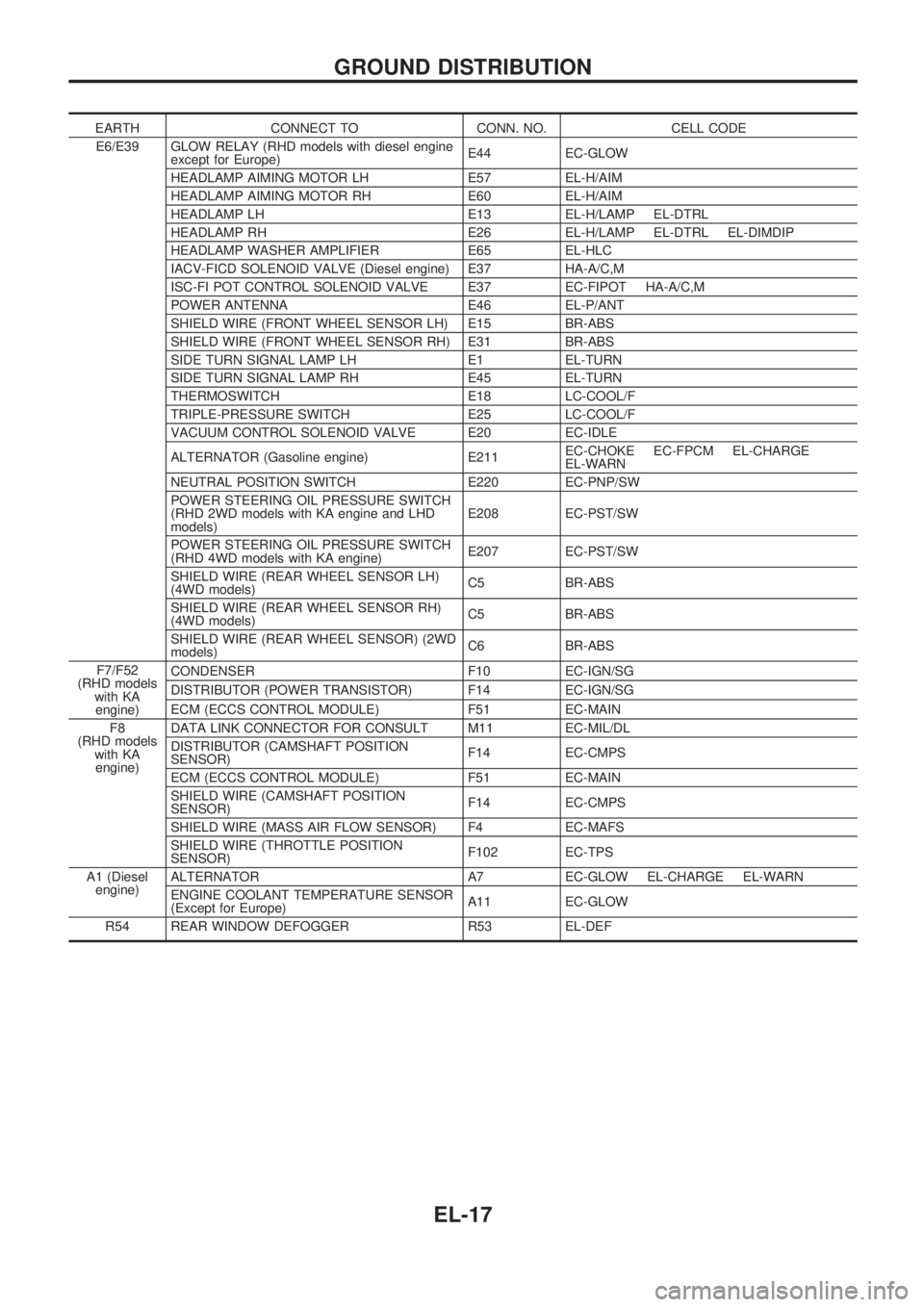
EARTH CONNECT TO CONN. NO. CELL CODE
E6/E39 GLOW RELAY (RHD models with diesel engine
except for Europe)E44 EC-GLOW
HEADLAMP AIMING MOTOR LH E57 EL-H/AIM
HEADLAMP AIMING MOTOR RH E60 EL-H/AIM
HEADLAMP LH E13 EL-H/LAMP EL-DTRL
HEADLAMP RH E26 EL-H/LAMP EL-DTRL EL-DIMDIP
HEADLAMP WASHER AMPLIFIER E65 EL-HLC
IACV-FICD SOLENOID VALVE (Diesel engine) E37 HA-A/C,M
ISC-FI POT CONTROL SOLENOID VALVE E37 EC-FIPOT HA-A/C,M
POWER ANTENNA E46 EL-P/ANT
SHIELD WIRE (FRONT WHEEL SENSOR LH) E15 BR-ABS
SHIELD WIRE (FRONT WHEEL SENSOR RH) E31 BR-ABS
SIDE TURN SIGNAL LAMP LH E1 EL-TURN
SIDE TURN SIGNAL LAMP RH E45 EL-TURN
THERMOSWITCH E18 LC-COOL/F
TRIPLE-PRESSURE SWITCH E25 LC-COOL/F
VACUUM CONTROL SOLENOID VALVE E20 EC-IDLE
ALTERNATOR (Gasoline engine) E211EC-CHOKE EC-FPCM EL-CHARGE
EL-WARN
NEUTRAL POSITION SWITCH E220 EC-PNP/SW
POWER STEERING OIL PRESSURE SWITCH
(RHD 2WD models with KA engine and LHD
models)E208 EC-PST/SW
POWER STEERING OIL PRESSURE SWITCH
(RHD 4WD models with KA engine)E207 EC-PST/SW
SHIELD WIRE (REAR WHEEL SENSOR LH)
(4WD models)C5 BR-ABS
SHIELD WIRE (REAR WHEEL SENSOR RH)
(4WD models)C5 BR-ABS
SHIELD WIRE (REAR WHEEL SENSOR) (2WD
models)C6 BR-ABS
F7/F52
(RHD models
with KA
engine)CONDENSER F10 EC-IGN/SG
DISTRIBUTOR (POWER TRANSISTOR) F14 EC-IGN/SG
ECM (ECCS CONTROL MODULE) F51 EC-MAIN
F8
(RHD models
with KA
engine)DATA LINK CONNECTOR FOR CONSULT M11 EC-MIL/DL
DISTRIBUTOR (CAMSHAFT POSITION
SENSOR)F14 EC-CMPS
ECM (ECCS CONTROL MODULE) F51 EC-MAIN
SHIELD WIRE (CAMSHAFT POSITION
SENSOR)F14 EC-CMPS
SHIELD WIRE (MASS AIR FLOW SENSOR) F4 EC-MAFS
SHIELD WIRE (THROTTLE POSITION
SENSOR)F102 EC-TPS
A1 (Diesel
engine)ALTERNATOR A7 EC-GLOW EL-CHARGE EL-WARN
ENGINE COOLANT TEMPERATURE SENSOR
(Except for Europe)A11 EC-GLOW
R54 REAR WINDOW DEFOGGER R53 EL-DEF
GROUND DISTRIBUTION
EL-17
Page 643 of 1659
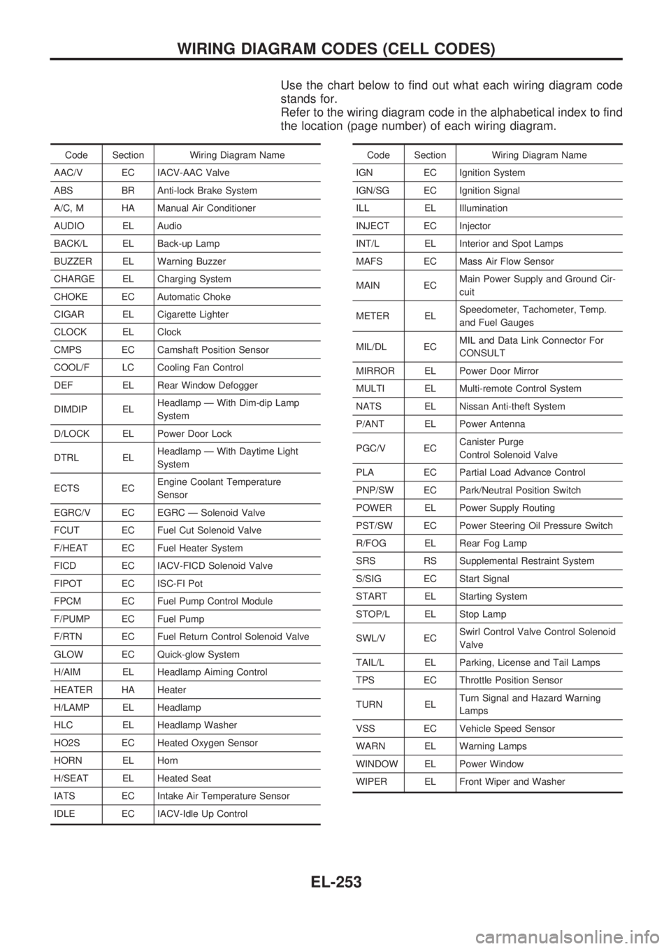
Use the chart below to find out what each wiring diagram code
stands for.
Refer to the wiring diagram code in the alphabetical index to find
the location (page number) of each wiring diagram.
Code Section Wiring Diagram Name
AAC/V EC IACV-AAC Valve
ABS BR Anti-lock Brake System
A/C, M HA Manual Air Conditioner
AUDIO EL Audio
BACK/L EL Back-up Lamp
BUZZER EL Warning Buzzer
CHARGE EL Charging System
CHOKE EC Automatic Choke
CIGAR EL Cigarette Lighter
CLOCK EL Clock
CMPS EC Camshaft Position Sensor
COOL/F LC Cooling Fan Control
DEF EL Rear Window Defogger
DIMDIP ELHeadlamp Ð With Dim-dip Lamp
System
D/LOCK EL Power Door Lock
DTRL ELHeadlamp Ð With Daytime Light
System
ECTS ECEngine Coolant Temperature
Sensor
EGRC/V EC EGRC Ð Solenoid Valve
FCUT EC Fuel Cut Solenoid Valve
F/HEAT EC Fuel Heater System
FICD EC IACV-FICD Solenoid Valve
FIPOT EC ISC-FI Pot
FPCM EC Fuel Pump Control Module
F/PUMP EC Fuel Pump
F/RTN EC Fuel Return Control Solenoid Valve
GLOW EC Quick-glow System
H/AIM EL Headlamp Aiming Control
HEATER HA Heater
H/LAMP EL Headlamp
HLC EL Headlamp Washer
HO2S EC Heated Oxygen Sensor
HORN EL Horn
H/SEAT EL Heated Seat
IATS EC Intake Air Temperature Sensor
IDLE EC IACV-Idle Up ControlCode Section Wiring Diagram Name
IGN EC Ignition System
IGN/SG EC Ignition Signal
ILL EL Illumination
INJECT EC Injector
INT/L EL Interior and Spot Lamps
MAFS EC Mass Air Flow Sensor
MAIN ECMain Power Supply and Ground Cir-
cuit
METER ELSpeedometer, Tachometer, Temp.
and Fuel Gauges
MIL/DL ECMIL and Data Link Connector For
CONSULT
MIRROR EL Power Door Mirror
MULTI EL Multi-remote Control System
NATS EL Nissan Anti-theft System
P/ANT EL Power Antenna
PGC/V ECCanister Purge
Control Solenoid Valve
PLA EC Partial Load Advance Control
PNP/SW EC Park/Neutral Position Switch
POWER EL Power Supply Routing
PST/SW EC Power Steering Oil Pressure Switch
R/FOG EL Rear Fog Lamp
SRS RS Supplemental Restraint System
S/SIG EC Start Signal
START EL Starting System
STOP/L EL Stop Lamp
SWL/V ECSwirl Control Valve Control Solenoid
Valve
TAIL/L EL Parking, License and Tail Lamps
TPS EC Throttle Position Sensor
TURN ELTurn Signal and Hazard Warning
Lamps
VSS EC Vehicle Speed Sensor
WARN EL Warning Lamps
WINDOW EL Power Window
WIPER EL Front Wiper and Washer
WIRING DIAGRAM CODES (CELL CODES)
EL-253