Page 304 of 1659
ECM TERMINALS AND REFERENCE VALUE
Remarks: Specification data are reference values, and are measured between each terminal andV39(ECCS ground) with a voltme-
ter.
TER-
MINAL
NO.WIRE
COLORITEM CONDITIONDATA
(DC voltage)
104 W/R Fuel pump relayIgnition switch ``ON''
For 5 seconds after turning ignition switch
``ON''
Engine is running.Approximately 1V
Ignition switch ``ON''
5 seconds after turning ignition switch ``ON''BATTERY VOLTAGE
(11 - 14V)
TROUBLE DIAGNOSIS FOR NON-DETECTABLE ITEMSKA
Fuel Pump (Cont'd)
EC-152
Page 305 of 1659
LHD MODELS
HEC563
TROUBLE DIAGNOSIS FOR NON-DETECTABLE ITEMSKA
Fuel Pump (Cont'd)
EC-153
Page 306 of 1659
RHD MODELS
HEC354
TROUBLE DIAGNOSIS FOR NON-DETECTABLE ITEMSKA
Fuel Pump (Cont'd)
EC-154
Page 307 of 1659

DIAGNOSTIC PROCEDURE
INSPECTION START
CHECK OVERALL FUNCTION.
1. Turn ignition switch ``ON''.
2. Pinch fuel feed hose with fingers.
Fuel pressure pulsation should be
felt on the fuel feed hose for 5 sec-
onds after ignition switch is turned
``ON''.
NG
cOK
INSPECTION END
CHECK POWER SUPPLY.
1. Turn ignition switch ``OFF''.
2. Disconnect fuel pump relay.
3. Turn ignition switch ``ON''.
4. Check voltage between terminals
V1,
V3and ground with CONSULT or
tester.
Voltage: Battery voltage
OK
cNG
Check the following.
l15A fuse
lHarness connectorsE101,M5
lHarness for open or
short between fuse and
fuel pump relay
If NG, repair harness or
connectors.
CHECK GROUND CIRCUIT.
1. Turn ignition switch ``OFF''.
2. Disconnect fuel pump harness connec-
tor.
3. Check harness continuity between ter-
minal
V6and body ground, relay ter-
minal
V5and terminalV5.
Continuity should exist.
If OK, check harness for short to
ground and short to power.
OK
cNG
Check the following.
lHarness connectorsC9,M121(LHD mod-
els for Europe)
lHarness connectorsE101,M5
lHarness for open or
short between fuel pump
and body ground
lHarness for open or
short between fuel pump
and fuel pump relay
If NG, repair open circuit,
short to ground or short to
power in harness or con-
nectors.
CHECK OUTPUT SIGNAL CIRCUIT.
1. Disconnect ECM harness connector.
2. Check harness continuity between
ECM terminal
104and terminalV2.
Continuity should exist.
If OK, check harness for short to
ground and short to power.
OK
cNG
Check the following.
lHarness connectorsE101,M5
lHarness connectorsM48,F54(RHD mod-
els)
lHarness for open or
short between ECM and
fuel pump relay
If NG, repair open circuit,
short to ground or short to
power in harness or con-
nectors.
VA
(Go to next page.)
SEF109U
SEF110U
SEF479P
SEF154U
.
.
.
.
.
TROUBLE DIAGNOSIS FOR NON-DETECTABLE ITEMSKA
Fuel Pump (Cont'd)
EC-155
Page 308 of 1659

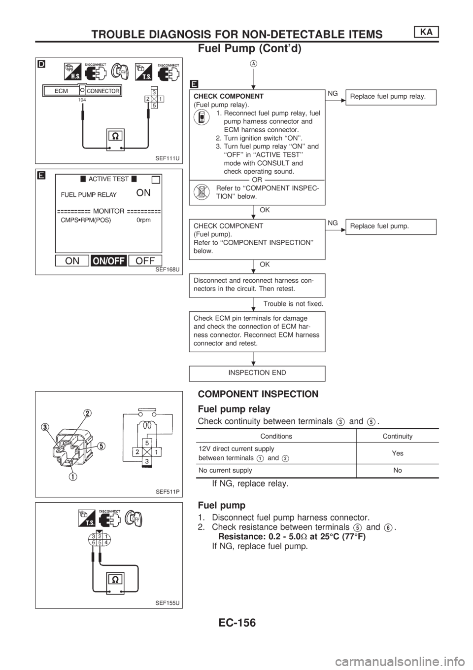
VA
CHECK COMPONENT
(Fuel pump relay).
1. Reconnect fuel pump relay, fuel
pump harness connector and
ECM harness connector.
2. Turn ignition switch ``ON''.
3. Turn fuel pump relay ``ON'' and
``OFF'' in ``ACTIVE TEST''
mode with CONSULT and
check operating sound.
----------------------------------------------------------------------------------------------------------------------------------OR----------------------------------------------------------------------------------------------------------------------------------
Refer to ``COMPONENT INSPEC-
TION'' below.
OK
cNG
Replace fuel pump relay.
CHECK COMPONENT
(Fuel pump).
Refer to ``COMPONENT INSPECTION''
below.
OK
cNG
Replace fuel pump.
Disconnect and reconnect harness con-
nectors in the circuit. Then retest.
Trouble is not fixed.
Check ECM pin terminals for damage
and check the connection of ECM har-
ness connector. Reconnect ECM harness
connector and retest.
INSPECTION END
COMPONENT INSPECTION
Fuel pump relay
Check continuity between terminalsV3andV5.
Conditions Continuity
12V direct current supply
between terminals
V1andV2Yes
No current supply No
If NG, replace relay.
Fuel pump
1. Disconnect fuel pump harness connector.
2. Check resistance between terminals
V5andV6.
Resistance: 0.2 - 5.0Wat 25ÉC (77ÉF)
If NG, replace fuel pump.
SEF111U
SEF168U
SEF511P
SEF155U
.
.
.
.
.
TROUBLE DIAGNOSIS FOR NON-DETECTABLE ITEMSKA
Fuel Pump (Cont'd)
EC-156
Page 328 of 1659
CAUTION:
lDisassembly and assembly of the injection pumps should be done only in service shops autho-
rized by NISSAN or by the pump manufacturer.
lThe pump tester is required for servicing the pump.
lBefore removing fuel injection pump from vehicle, check closely to make sure that it is definitely
malfunctioning.
For TD25 engine models with Nissan Anti-Theft System (NATS)
lFor inspection of coded solenoid unit (CSOLU), refer to NATS (Diesel) in EL section.
lWhen replacing injection pump assembly along with CSOLU, perform NATS initialisation with
CONSULT.
For initialisation procedure, refer to NATS (Diesel) in EL section.
Fuel System
SEF378RA
INJECTION SYSTEMTD
EC-176
Page 330 of 1659

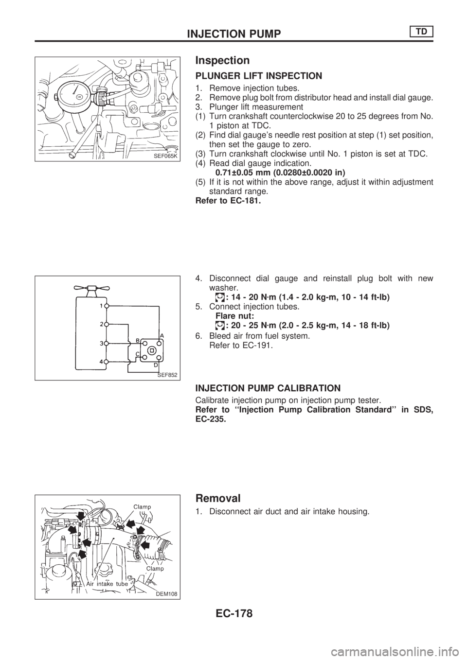
Inspection
PLUNGER LIFT INSPECTION
1. Remove injection tubes.
2. Remove plug bolt from distributor head and install dial gauge.
3. Plunger lift measurement
(1) Turn crankshaft counterclockwise 20 to 25 degrees from No.
1 piston at TDC.
(2) Find dial gauge's needle rest position at step (1) set position,
then set the gauge to zero.
(3) Turn crankshaft clockwise until No. 1 piston is set at TDC.
(4) Read dial gauge indication.
0.71 0.05 mm (0.0280 0.0020 in)
(5) If it is not within the above range, adjust it within adjustment
standard range.
Refer to EC-181.
4. Disconnect dial gauge and reinstall plug bolt with new
washer.
:14-20Nzm (1.4 - 2.0 kg-m, 10 - 14 ft-lb)
5. Connect injection tubes.
Flare nut:
:20-25Nzm (2.0 - 2.5 kg-m, 14 - 18 ft-lb)
6. Bleed air from fuel system.
Refer to EC-191.
INJECTION PUMP CALIBRATION
Calibrate injection pump on injection pump tester.
Refer to ``Injection Pump Calibration Standard'' in SDS,
EC-235.
Removal
1. Disconnect air duct and air intake housing.
SEF065K
SEF852
DEM108
.
INJECTION PUMPTD
EC-178
Page 331 of 1659
2. Remove injection tube.
Cover the injection nozzle assembly with a plug to prevent
dust entry.
3. Turn ignition switch to OFF position and disconnect wire har-
ness connectors connected to the injection pump.
4. Remove accelerator wire and disconnect overflow hose, fuel
inlet hose and fuel return hose.
5. Remove injection pump drive gear cover.
6. Loosen injection pump drive gear nut and remove drive gear
by using puller.
DEM025
DEM058
SEF061K
DEF012
DEM062
INJECTION PUMPTD
Removal (Cont'd)
EC-179